Novel receiver architectures for mobile communications
Bạn đang xem bản rút gọn của tài liệu. Xem và tải ngay bản đầy đủ của tài liệu tại đây (6.06 MB, 210 trang )
NOVEL RECEIVER ARCHITECTURES
FOR
MOBILE COMMUNICATIONS
ANG WEE PENG
(B.Eng. (EE), M.Sc. (EE), NUS)
A THESIS SUBMITTED
FOR THE DEGREE O F DOCTOR OF PHILO SOPHY
DEPARTMENT OF ELECTRICAL & COMPUTER ENGINEERING
NATIONAL UNIVERSITY OF SINGAPORE
2003
Acknowledgments
I would like to thank my supervisors, A/Prof H.K. Garg and A/Prof Farhang B.
Boroujeny for their guidance and patience throughout my candidature. I would
also like to thank A/Prof Garg for introducing me to the exciting area of research
on turbo codes, and for his comments and suggestions throughout the course of
this research program.
On a personal note, I would like to dedicate this thesis to my wife Lai Pheng
for her support and love throughout this period.
i
Contents
Acknowledgments i
Summary vii
List of Tables ix
List of Figures x
List of Acronyms xvi
1 Introduction 1
1.1 Evolution Of Mobile Cellular Communications . . . . . . . . . . . . 3
1.1.1 First Generation (1G) Mobile Communications . . . . . . . 6
1.1.2 Second Generation (2G) Mobile Communications . . . . . . 9
1.1.3 Third Generation Mobile Communications . . . . . . . . . . 15
1.1.4 Beyond Third Generation Mobile Communications . . . . . 19
1.2 Mobile Propagation Channel Impairments & Optimum Receivers
For Fading Channels . . . . . . . . . . . . . . . . . . . . . . . . . . 21
1.3 Applications of Adaptive Signal Processing in Communications . . . 25
1.3.1 Channel Modelling . . . . . . . . . . . . . . . . . . . . . . . 25
1.3.2 Channel Equalization . . . . . . . . . . . . . . . . . . . . . . 27
1.3.3 Linear Prediction . . . . . . . . . . . . . . . . . . . . . . . . 29
1.3.4 Inte r f erence Cancellation . . . . . . . . . . . . . . . . . . . . 31
ii
1.4 Aim of Thesis . . . . . . . . . . . . . . . . . . . . . . . . . . . . . . 31
1.5 Contributions of Thesis . . . . . . . . . . . . . . . . . . . . . . . . . 33
1.6 Organization of Thesis . . . . . . . . . . . . . . . . . . . . . . . . . 35
2 Review of Variable Step-Size Least Mean Square Algorithms 37
2.1 Intr oducti on . . . . . . . . . . . . . . . . . . . . . . . . . . . . . . . 37
2.2 Problem Formulation of Tracking a Non-
stationary Environment for Adaptive Filters . . . . . . . . . . . . . 39
2.3 Analysis of Mean Square Error of LMS Algorithm in Tracking a
Non-stationary Environment . . . . . . . . . . . . . . . . . . . . . . 41
2.4 Derivat ion of Optimum Step-Size Parameters . . . . . . . . . . . . . 45
2.4.1 Optimum Step-Size Parameters For Multiple Step-Size LMS
Algorithm . . . . . . . . . . . . . . . . . . . . . . . . . . . . 45
2.4.2 Optimum St ep-Size Parameter For Common Step-Size LMS
Algorithm . . . . . . . . . . . . . . . . . . . . . . . . . . . . 46
2.4.3 Stability Conditions . . . . . . . . . . . . . . . . . . . . . . 47
2.5 Existing Variable Step-Size LMS Algorithms . . . . . . . . . . . . . 48
2.5.1 Classi¯cation and Naming Convention of the VSLMS Algo-
rithms . . . . . . . . . . . . . . . . . . . . . . . . . . . . . . 50
2.5.2 Common Step-Size VSL M S Algorithm - Mathews' Algorithm 50
2.5.3 Benveniste's Algorithm - Another Common Step-Size VSLMS
Algorithm . . . . . . . . . . . . . . . . . . . . . . . . . . . . 52
2.5.4 Mathews' Multiple Step-Size VSLMS Algorithm . . . . . . . 53
2.5.5 Benveniste's Multiple Step-Size VSL MS Algorithm . . . . . 54
2.5.6 Multiplicative Update Versus Linear Update Of Step-Size
Parameter . . . . . . . . . . . . . . . . . . . . . . . . . . . . 54
2.5.7 Normalization of Adaptation Parameter ½ . . . . . . . . . . 55
2.5.8 Sign Algorithms . . . . . . . . . . . . . . . . . . . . . . . . . 55
2.6 Performance of Common Step-Size VSLMS Algorithms . . . . . . . 56
iii
2.6.1 Simulat ion Set-up . . . . . . . . . . . . . . . . . . . . . . . . 56
2.6.2 Mathews' Vs Benveniste's Common Step-Size VSLMS Algo-
rithms . . . . . . . . . . . . . . . . . . . . . . . . . . . . . . 58
2.6.3 Performance Under High And Low SNR . . . . . . . . . . . 58
2.7 Performance of Multiple Step-Size VSLMS Algorithms In Tracking
A Multipath Channe l . . . . . . . . . . . . . . . . . . . . . . . . . . 61
2.7.1 Non-stationary Channel Model . . . . . . . . . . . . . . . . 61
2.7.2 Simulat ion Set-up . . . . . . . . . . . . . . . . . . . . . . . . 62
2.7.3 Multiple Step-Size Vs Common Step-Size . . . . . . . . . . . 63
2.7.4 Mathews' Vs Benveniste's Multiple Step-Size VSLMS Algo-
rithms . . . . . . . . . . . . . . . . . . . . . . . . . . . . . . 65
2.8 Summary . . . . . . . . . . . . . . . . . . . . . . . . . . . . . . . . 67
3 A New Class of Variable Step-Size LMS Algorithms 69
3.1 Intr oducti on . . . . . . . . . . . . . . . . . . . . . . . . . . . . . . . 69
3.2 A New Class of VSLMS Algorithms . . . . . . . . . . . . . . . . . . 71
3.2.1 Benveniste's Multiple Step-Size Algorithm . . . . . . . . . . 71
3.2.2 A New Class of Multiple Step-Size VSLMS Algorithm . . . . 72
3.2.3 Gradient Filtering View of the Proposed and Benveniste's
Algorithms . . . . . . . . . . . . . . . . . . . . . . . . . . . 73
3.2.4 A New Class of Common Step-Size V SL M S Algorithm . . . 73
3.3 Classi¯cation of the Algorithms and Computational Complexity . . 74
3.4 Simulat ion Results . . . . . . . . . . . . . . . . . . . . . . . . . . . 74
3.4.1 Tracking a T ime-Varying Plant Using Proposed c-VSLMS
Algorithms . . . . . . . . . . . . . . . . . . . . . . . . . . . 76
3.4.2 Tracking Performance In Multipath Channel Using Proposed
m-VSLMS Algorithms . . . . . . . . . . . . . . . . . . . . . 77
3.5 Summary . . . . . . . . . . . . . . . . . . . . . . . . . . . . . . . . 87
iv
4 Turbo Codes Fundamentals 88
4.1 Intr oducti on . . . . . . . . . . . . . . . . . . . . . . . . . . . . . . . 88
4.2 Convolutional Codes . . . . . . . . . . . . . . . . . . . . . . . . . . 90
4.2.1 Encoding Convolutional Codes . . . . . . . . . . . . . . . . . 90
4.2.2 Representation of Convolutional Codes : Stat e Diagram and
Trellis Diagram . . . . . . . . . . . . . . . . . . . . . . . . . 91
4.2.3 Recursive Systematic C onvolutional (RSC) Codes . . . . . . 92
4.3 The Turbo Encoder . . . . . . . . . . . . . . . . . . . . . . . . . . . 94
4.4 The Turbo Decoder . . . . . . . . . . . . . . . . . . . . . . . . . . . 96
4.4.1 Maximum A Posteriori (MAP) Algorithm . . . . . . . . . . 98
4.4.2 Log-MAP Algorit hm . . . . . . . . . . . . . . . . . . . . . . 101
4.4.3 Max-Log-MAP Algorithm . . . . . . . . . . . . . . . . . . . 103
4.4.4 Requirements For Turbo Decoding In Rayleigh Fading Chan-
nels . . . . . . . . . . . . . . . . . . . . . . . . . . . . . . . . 103
4.4.5 Simulat ion Set-up . . . . . . . . . . . . . . . . . . . . . . . . 105
4.4.6 Performance Of Turbo Decoder In AWGN . . . . . . . . . . 106
4.4.7 Sensitivity Of Turbo Decoder To Errors in E
b
=N
o
. . . . . . 106
4.4.8 Performance Of Turbo Decoder In Rayleigh Fading Channels 108
4.5 Other Related Coding Schemes . . . . . . . . . . . . . . . . . . . . 110
4.6 Summary . . . . . . . . . . . . . . . . . . . . . . . . . . . . . . . . 111
5 Channel Estimation For Turbo Decoding Over Rayleigh Fading
Channels 113
5.1 Intr oducti on . . . . . . . . . . . . . . . . . . . . . . . . . . . . . . . 113
5.2 System Model . . . . . . . . . . . . . . . . . . . . . . . . . . . . . . 117
5.2.1 Transmitter Model . . . . . . . . . . . . . . . . . . . . . . . 117
5.2.2 Channel Model . . . . . . . . . . . . . . . . . . . . . . . . . 118
5.2.3 Receiver Model With Iterative Channel Estimation . . . . . 119
5.3 Proposed Channel Estimation Filters . . . . . . . . . . . . . . . . . 125
v
5.3.1 Fixed Characteristics Channel Estimation Filters . . . . . . 126
5.3.2 Adaptive Channel Estimation Filter . . . . . . . . . . . . . . 129
5.3.3 Comparison of Computational Complexity of Channel Esti-
mation Filters . . . . . . . . . . . . . . . . . . . . . . . . . . 133
5.4 Simulat ion Set-up . . . . . . . . . . . . . . . . . . . . . . . . . . . . 136
5.5 Selection of Filter Parameters . . . . . . . . . . . . . . . . . . . . . 138
5.5.1 Parameters For Fixed Characteristics Filter . . . . . . . . . 138
5.5.2 Parameters For Variable Step-Size LMS Filter . . . . . . . . 142
5.6 Performance in Stationary Rayleigh Fading Channel . . . . . . . . . 144
5.6.1 Slow Normalized Fading Rate, f
d
T
s
= 0:005 . . . . . . . . . 144
5.6.2 Fast Normalized Fading Rate, f
d
T
s
= 0:02 . . . . . . . . . . 151
5.6.3 Convergence of Mean Square Error of Channel Estimates . . 153
5.6.4 Soft Decision Feedback Versus Hard Decision Feedback . . . 158
5.6.5 Other Feedback Schemes . . . . . . . . . . . . . . . . . . . . 165
5.7 Performance in Non-stationary Rayleigh Fading Channel . . . . . . 168
5.8 Performance of Prop osed c-VSLMS-III-M Algorithm Versus Exist-
ing c-VSLMS-M Algorithms . . . . . . . . . . . . . . . . . . . . . . 173
5.9 Summary . . . . . . . . . . . . . . . . . . . . . . . . . . . . . . . . 173
6 Conclusions 177
6.1 Summary . . . . . . . . . . . . . . . . . . . . . . . . . . . . . . . . 177
6.2 Publications . . . . . . . . . . . . . . . . . . . . . . . . . . . . . . . 180
6.3 Future Wor k . . . . . . . . . . . . . . . . . . . . . . . . . . . . . . . 181
References 183
vi
Summary
In digital communications, especially for mobile communications, adaptive signal
processing techniques are widely used to improve the system performance. For ex-
ample, adaptive equalization is needed to combat a multipath propagation channel
that is usually unknown a-priori. Furthermore, the propagation channel can also
be time varying as the mobile station transceiver is not static. Thus, the adaptive
equalization algorithms not only need to converge quickly to a steady state dur-
ing a short training stage, they also need to track the changes of the propagation
channel to maintain an acceptable performance.
The major contributions of this thesis are as follows.
1. New Class of Variable Step-size Least Mean Square Algorithms. The
¯rst contribution of this thesis is the development of a new class of variable step-
size least mean square (VSLMS) algorithms that shows fast convergence and good
tracking properties in a non-stationary environment. This new class of VSLMS
algorithms is shown to be suitable for channel estimation that is essential for good
performance in a mobile propagation environment. It is demonstrated that the
algorithms are superior compared to existing algorithms in performance and do
not require a signi¯cant increase in complexity.
2. New Iterative Channel Estimation Receiver Architecture. The sec-
ond contribution resulting from this research is the development of a new receiver
architecture incorporating iterative channel estimation. This receiver architecture
vii
leads to a signi¯cant improvement in coding gain over one that does not perform
iterative channel estimation, for turbo decoding over fading channels. This pro-
posed receiver architecture uses time multiplexed pilot symbols for initial channel
estimation which is further improved by feeding back only the detected message
(systematic) bits after each decoding iteration. We also demonstrate that our re-
ceiver architecture achieves performance that is same as that of an existing one
that uses both message and parity bits for improving the channel estimates, but
with reduced complexity.
3. New Fixed Characteristics Channel Estimation Filters. The third
cont ri but ion is the establishment of the suitability of di®erent channel estima-
tion ¯lters and their parameters for good performance under known, unknown and
non-stationary fading rates. This has not been thoroughly investigated in the ex-
isting literature. The FIR (¯nite impulse response) and the DFT (discrete Fourier
transform) ¯lters are shown to be suitable under both slow and fast fading when
the fading rates are known. For good performance, we found that t he cut-o® fre-
quency of the channel estimation ¯lters needs to be greater than the normalized
fading rate (about 1.1 to 1.5 times) as opposed to being equal to the normalized
fading rate as proposed previously. As for the equal weight moving average ¯lter,
it is suitable only under slow fading when the fading rate is know n.
4. Adaptive Channel Estimation Filter. The fourth contribution is the suc-
cessful application of the new class of VSLMS algorit hms developed here as an
appropriate channel estimation ¯lter in t he proposed receiver architecture. This
VSLMS ¯lter does not assume a-priori knowledge of the fading rate. When the
fading rate changes, the VSLMS ¯lter is also able to track the channel well, achiev-
ing performance better than that of the equal weight moving average and the FIR
¯lters. The equal weight moving average and FIR ¯lters have ¯xed characteristics
and are hence unable to respond to a channel that has a time varying fading rate.
viii
List of Tables
3.1 Classi¯cation of VSLMS Algorithms and Complexity . . . . . . . . 75
5.1 Complexity of Channel Estimation Filters . . . . . . . . . . . . . . 136
ix
List of Figures
1.1 Evolution of Mobile Cellular Communications . . . . . . . . . . . . 4
1.2 Concept of Mobile Cellular Communications . . . . . . . . . . . . . 7
1.3 Fade margin versus percent reliability for Rayleigh fading . . . . . . 8
1.4 Signal processing operations in GSM . . . . . . . . . . . . . . . . . 10
1.5 Data structure within a normal GSM burst. . . . . . . . . . . . . . 12
1.6 Generalized Viterbi Equalizer . . . . . . . . . . . . . . . . . . . . . 14
1.7 3G Terrestrial Radio Interfaces . . . . . . . . . . . . . . . . . . . . 16
1.8 Rake receiver . . . . . . . . . . . . . . . . . . . . . . . . . . . . . . 17
1.9 4G and other communication systems . . . . . . . . . . . . . . . . . 20
1.10 Adaptive System Modelling . . . . . . . . . . . . . . . . . . . . . . 26
1.11 Adaptive Channel Identi¯cation . . . . . . . . . . . . . . . . . . . . 27
1.12 Adaptive Equalization . . . . . . . . . . . . . . . . . . . . . . . . . 28
1.13 Autoregressive modelling . . . . . . . . . . . . . . . . . . . . . . . . 29
1.14 Linear prediction . . . . . . . . . . . . . . . . . . . . . . . . . . . . 30
1.15 Principle of Interference Cancellation . . . . . . . . . . . . . . . . . 32
2.1 Mo dellin g problem in non-stationary environment . . . . . . . . . . 39
2.2 Simulat ion set-up for comparing tracking performance of existing
common step-size VSLMS algorithms. . . . . . . . . . . . . . . . . . 56
2.3 Performance of c-VSLMS-I-M vs c-VSLMS-II-M algorithms. . . . . 59
2.4 Performance of c-VSLMS-I-M vs c-VSLMS-II-M algorithms for high
and low SNR. . . . . . . . . . . . . . . . . . . . . . . . . . . . . . . 60
x
2.5 Simulat ion set-up for comparing tracking performance of existing
mult iple step-size VSLMS algorithms. . . . . . . . . . . . . . . . . . 62
2.6 Performance of c-VSLMS-I-M vs m-VSLMS-I-M algorithms in track-
ing a 2-path multipath channel where the perturbations for each tap
are di®erent. . . . . . . . . . . . . . . . . . . . . . . . . . . . . . . . 64
2.7 Performance of m-VSLMS-I-M vs m-VSLMS-II-M algorithms in track-
ing a 2-path multipath channel where the perturbations for each tap
are di®erent. SNR=20 dB. . . . . . . . . . . . . . . . . . . . . . . . 66
2.8 Performance of m-VSLMS-I-M vs m-VSLMS-II-M algorithms in track-
ing a 2-path multipath channel from low to high SNR. . . . . . . . 67
3.1 Tracking performance of c-V SL M S algorithms using multiplicative
update recursion. The plant and adaptive ¯lter length is equal to
16. Variance of plant input , ¾
2
x
= 1:0, plant measurement noise,
¾
2
e
o
= 0:01, process noise variance of plant tap weights, ¾
2
²
o
= 10
¡6
,
½ = 2 £ 10
¡4
is used in all the algorithms, and ® = 0:95 is used in
c-VSLMS-III-M. . . . . . . . . . . . . . . . . . . . . . . . . . . . . 78
3.2 Variation of excess MSE obtained as a function of ½. This compares
the sensitivity of various c-VSLMS algorithms to the par ameter ½.
The simulation parameters are the same as those used in Figure 3.1. 79
3.3 Performance of proposed c-V SL MS-III-M algorithm compared with
c-VSLMS-I-M and c-VSLMS-II-M algorithms for high and low SNR. 80
3.4 Simulat ion set-up for comparing tracking performance of proposed
and existing m-VSLMS-M algorithms. . . . . . . . . . . . . . . . . . 81
3.5 Tracking performance of m-VSLMS algorithms using multiplica-
tive update recursion under high SNR and slow channel variations.
SNR= 20 dB, f
d
= 1 Hz and ¯ = 0:95 are used in all simula-
tions. ½
o
= 2 £ 10
¡2
is used in m-VSLMS-I-M, m-V SL M S-II-M &
m-VSLMS-III-M. ® = 0:95 is used in m-VSLMS-III-M. . . . . . . . 84
xi
3.6 Tracking p e r f ormance of m-VSLMS algorithms using multiplicative
update recursion under high SNR and fast channel variations. The
simulation conditions are as per Figure 3.5 except that the rate of
separation of th e 2 multipath is increased 10 times, ½
o
= 0:07 for
m-VSLMS-I-M & ½
o
= 0:05 for m-VSLMS-II-M and m-VSLMS-III-M. 85
3.7 Tracking p e r f ormance of m-VSLMS algorithms using multiplicative
update r ecursion under low SNR(SNR= 0 dB) and slow channel
variations. The rest of the simulation conditions are the same as in
Figure 3.5. . . . . . . . . . . . . . . . . . . . . . . . . . . . . . . . . 86
4.1 (2,1,2) Convolutional enco der. . . . . . . . . . . . . . . . . . . . . . 90
4.2 State diagram of (2,1,2) convolutional encoder. . . . . . . . . . . . . 92
4.3 Trellis diagram of (2,1,2) convolutional encoder. . . . . . . . . . . . 93
4.4 (2,1,2) recursive systematic convolutional encoder. . . . . . . . . . . 94
4.5 State diagram of (2,1,2) RSC encoder. . . . . . . . . . . . . . . . . 95
4.6 Trellis diagram of (2,1,2) recursive systematic convolutional encoder. 96
4.7 Turbo encoder. . . . . . . . . . . . . . . . . . . . . . . . . . . . . . 97
4.8 Turbo decoder. . . . . . . . . . . . . . . . . . . . . . . . . . . . . . 98
4.9 Performance of turbo decoder in AWGN channel . . . . . . . . . . . 107
4.10 Performance comparison of Log-MAP and max-Log-MAP turbo de-
co der in AWGN channe l . . . . . . . . . . . . . . . . . . . . . . . . 108
4.11 Sensitivity of turbo decoder to SNR e r r ors in AWGN channel . . . . 109
4.12 Performance of turbo deco ders in Rayleigh fading channels. . . . . . 110
5.1 Transmitter model. . . . . . . . . . . . . . . . . . . . . . . . . . . . 118
5.2 Proposed receiver model with iterative channel estimation for sta-
tionary and non-stationary Rayleigh fading channel. . . . . . . . . . 120
5.3 Frequency of response of 61-taps equal weight moving average ¯ l-
ter compared to 151-taps and 301-taps FIR ¯lt ers designed using
Hamming window. Cut-o® frequency is the same for all ¯lters. . . . 128
xii
5.4 Ope r ati on of proposed VSLMS algorithm in obtaining the channel
estimation ¯lter coe±cients. . . . . . . . . . . . . . . . . . . . . . . 130
5.5 BER as a function of ¯lter parameters for equal weight moving av-
erage and DFT estimation ¯lters. Top: f
d
T
s
= 0:005; E
b
=N
o
= 5
dB. Bottom: f
d
T
s
= 0:02; E
b
=N
o
= 6 dB. . . . . . . . . . . . . . . . 139
5.6 BER as a function of ¯lter parameters for FIR estimation ¯lters.
Top: f
d
T
s
= 0:005; E
b
=N
o
= 5 dB. Bottom: f
d
T
s
= 0:02; E
b
=N
o
= 6
dB. . . . . . . . . . . . . . . . . . . . . . . . . . . . . . . . . . . . . 140
5.7 MSE vs number of pilot symbols for c-VSLMS-III-M ¯lter for dif-
ferent step-size adaptation parameter, ½
o
and f
d
T
s
. Number of co-
e±cients is 37. E
b
=N
o
= 5 dB . . . . . . . . . . . . . . . . . . . . . 143
5.8 BER as a function of ¯lter length of c-VSLMS-III-M ¯lter for dif-
ferent step-size adaptation parameter, ½
o
. E
b
=N
o
= 5 dB. Top :
f
d
T
s
= 0:005, Bott om : f
d
T
s
= 0:02. . . . . . . . . . . . . . . . . . . 145
5.9 BER vs E
b
=N
o
at normalized fading rate, f
d
T
s
= 0:005, for various
channel est im ati on ¯lters. All channel estimation ¯lters except c-
VSLMS-III-M assume knowle dge of the channel normaliz ed fading
rate to set the appropriate cut-o® frequency and ¯lter length. . . . 147
5.10 Comparison of Log-MAP and max-Log-MAP decoder at f
d
T
s
=
0:005. All channel estimation ¯lters except c-VSLMS-I II-M assume
knowledge of the channel normalized fading rate to set the appro-
priate cut-o® frequency and ¯lter length. . . . . . . . . . . . . . . . 149
5.11 Combati ng BER °oor at f
d
T
s
= 0:005, with modi¯cation of channel
inte r leaver depth and frame size. Channel estimation ¯lter is the
FIR ¯lter. For both (a) & (b) frame size=2500. Channel interleavers
for ( a) & (b) are 50x51 and 100x25 respectively. For (c), frame
size=5000 & channel interleaver is 100x51. . . . . . . . . . . . . . . 150
xiii
5.12 BER vs E
b
=N
o
at normalized fading rate, f
d
T
s
= 0:02, for various
channel est im ati on ¯lters. All channel estimation ¯lters except c-
VSLMS-III-M assume knowle dge of the channel normaliz ed fading
rate to set the appropriate cut-o® frequency and ¯lter length. . . . 152
5.13 Comparison of Log-MAP and max-Log-MAP decoder at f
d
T
s
=
0:02. All channel estimat ion ¯lters except c-VSLMS-III-M assume
knowledge of the channel normalized fading rate to set the appro-
priate cut-o® frequency and ¯lter length. . . . . . . . . . . . . . . . 154
5.14 MSE vs E
b
=N
o
in each iteration for f
d
T
s
= 0:02 & f
d
T
s
= 0:005.
Channel estimation ¯lter is FIR ¯lter. . . . . . . . . . . . . . . . . . 156
5.15 BER vs E
b
=N
o
after the 5-th turbo decoding iteration from using 3
to 5 ite r ations of channel estimation at f
d
T
s
= 0:02 & f
d
T
s
= 0:005.
Channel estimation ¯lter is FIR ¯lter. . . . . . . . . . . . . . . . . . 157
5.16 BER vs E
b
=N
o
comparing soft decision and hard decision feedback
at f
d
T
s
= 0:02 & f
d
T
s
= 0:005. Channel estimation ¯lter is FIR ¯lter.159
5.17 MSE vs E
b
=N
o
at f
d
T
s
= 0:02 in each iteration for both soft decision
and hard decision feedback. . . . . . . . . . . . . . . . . . . . . . . 161
5.18 BER vs E
b
=N
o
at f
d
T
s
= 0:02 in each iteration for both soft decision
and hard decision feedback. . . . . . . . . . . . . . . . . . . . . . . 162
5.19 MSE vs E
b
=N
o
at f
d
T
s
= 0:005 in each iteration for both soft decision
and hard decision feedback. . . . . . . . . . . . . . . . . . . . . . . 163
5.20 BER vs E
b
=N
o
at f
d
T
s
= 0:005 in each iteration for both soft decision
and hard decision feedback. . . . . . . . . . . . . . . . . . . . . . . 164
5.21 Comparison b etween proposed receiver where only systematic bits
are used to re¯ne channel estimation and the case where both sys-
tematic and parity bits are used. Top ¯gure : f
d
T
s
= 0:005. Bottom
¯gure : f
d
T
s
= 0:02. . . . . . . . . . . . . . . . . . . . . . . . . . . . 167
5.22 Slow rate of change of normalized fading rate - Top: Pro¯le A,
Bottom: Pro¯le B. . . . . . . . . . . . . . . . . . . . . . . . . . . . 169
xiv
5.23 BER (Top) and FER (Bottom) as a function of time (frame number)
under time varying normalized fading rate following Pro¯le A. . . . 171
5.24 BER (Top) and FER (Bottom) as a function of time (frame number)
under time varying normalized fading rate following Pro¯le B. . . . 172
5.25 BER (Top) and FER (Bottom) as a function of time (frame number)
under 2 times the rate of change of fading rate of Section 5.7 com-
paring proposed c-VSLMS-III-M ¯lter with existing c-VSLMS-I-M
¯lter. . . . . . . . . . . . . . . . . . . . . . . . . . . . . . . . . . . . 174
5.26 BER (Top) and FER (Bottom) as a function of time (frame number)
under 4 times the rate of change of fading rate of Section 5.7 com-
paring proposed c-VSLMS-III-M ¯lter with existing c-VSLMS-I-M
¯lter. . . . . . . . . . . . . . . . . . . . . . . . . . . . . . . . . . . . 175
xv
List of Acronyms
1G First Generation Mobile Communications
2G Second Generation Mobile Communications
3G Third Generation Mobile Communications
4G Fourth Generation Mobile Communications
AMPS Advanced Mobile Phone Service
AR Autoregressive
AWGN Additive White Gaussian Noise
BPSK Binary Phase Shift Keying
BT Bandwidth-Time Product
CDMA Co de Division Multiple Access
DFT Discrete Fourier Transform
DSP Digital Signal Processor
c-VSLMS Common Step-size VSLMS
D-AMPS Digital AMPS
DECT Digital Enhanced Cordless Telephone
EDGE Enhanced Data-Rates for GSM Evolution
FFT Fast Fourier Transform
FEC Forward Error Correction
FDMA Frequency Division Multiple Access
FIR Finite Impulse Response
xvi
FM Frequency Modulation
GMSK Gaussian Minimum Shift Keying
GSM Global System for Mobile
IMT International Mobile Telephony
IMT-DS IMT Direct Spread
IMT-FT IMT Frequency Tim e
IMT-MC IMT Multi-Carrier
IMT-TC IMT Time Code
IMT-SC IMT Single Carrier
ISI Inte r -Symbol Interference
ITU Inte r nati onal Telecommunications Union
LAN Local Area Network
LMMSE Linear Minimum Mean Square Error
LMS Least Mean Square
MAI Multiple Access Interference
MAP Maximum A-Posteriori algorithm
MLSE Maximum Likelihood Sequence E stimator
MSE Mean Square Error
MUD Multi-User Detector
m-VSLMS Multiple Step-size VSLMS
OFDM Orthogonal Frequency Division Multiple Access
PDA Personal Digital Assistant
PDC Personal Digital Cellular
PIC Par allel Interference Canceller
PSK Phase Shift Keying
RSC Recursive Systematic C onvolutional codes
SIC Serial Interference Canceller
SNR Signal to Noise Ratio
TACS Total Access Communications System
xvii
TDMA Time Division Multiple Access
UMTS Unive r sal Mobile Telecommunication System
VSLMS Variable Step-size LMS
WARC World Administrative Radio Conference
WCDMA Wideband CDMA
WLAN Wireless Local Area Network
xviii
Chapter 1
Introduction
Advances in technology over the past two decades have r esulted in the wide-spread
use of wireless communication systems. The most successful of these in terms of
number of users and provision of wide area coverage and mobility to users are
the mobile cellular communicat ion systems. Prior to the cellular systems, there
were mobile radio networks. However, these were characterized by low data rate
and mobility compared to the cellular network. Mobile cellular communication
systems have given people the freedom to communicate with one another and
access information on the move, anywhere, anytime. The increasing numb er of
mobile phone users and the demand for high data rate services other than voice
have fuelled a constant search for techniques to maximize the syste m throughput
given the limited bandwidth and the need to conserve battery power in these mobile
devices.
One area of active research and development is in improving battery technology
and development of low power devices to lengthen t he usage times. The other area
is the development of high performance radio frequency components with low noise
¯gures to improve receiver sensitivity. Another area of active research is related
to the challenges posed by the impairments caused by the mobile propagation
channel. The mobile propagation channel causes impairment in the form of signal
1
fading and rapid phase changes. These have adverse e®ects on the transmitted
signal, especially for coherent demodulation of commonly used bandwidth e±cient
mo dulat ion schemes such as PSK and QAM modulated signals. These e®ects lead
to high bit error rates (BER) if they are not compensated by the r e ceiver.
The development of robust modulation schemes is one way to counter the neg-
ative e®ects introduced by the channel. However, this is usually not su±cient to
guarant ee good performance. The development of forward error correction (FEC)
co des is also needed to complement a robust modulation scheme to counter the
detrimental e®ects introduced by the channel. The convolutional codes and r e-
cently turbo codes are used to mitigate the amplitude fading e®ects of large scale
path loss and small scale channel fading to improve system performance. However,
for enhanc ed pe r formance of the FEC, there is also a need to estimate the chan-
nel coe±cients. For example, the channel estimates allow the receiver to r e move
the phase rotations caused by the channel to achieve coherent demodulation of
quadrature amplitude modulation (QAM) and phase shift keying (PSK) modu-
lated signals. Similarly knowledge of the fading amplitude enables the calculation
of the branch metrics that improves the Viterbi decoding of convolutional codes
and maximum a-posteriori (MAP) decoding of turbo codes.
Unfortunately, in practice the characteristics of the mobile propagation channel
is usually unknown a-priori. Also it changes as a result of the movement of the
mobile user. Hence, channel estimation is usually performed by transmitting known
pilot symbols. Such a scheme is investigated in [1] and implemented in commercial
digital cellular systems such GSM, WCDMA [2], and cdma2000 [3]. These pilot
symbols can be time-multiplexed with the transmitted symbols, e.g. in both the
downlink and uplink of GSM syst ems, the downlinks of WCDMA, and cdma2000
systems. They can also be transmitted in parallel in a separate channel as in the
uplinks of WCDMA and cdma2000 systems so as to enable the channel estimation
algorithms to derive the channel coe±cients. As the use of pilot symbols consumes
bandwidth and available power, it is desirable to use a minimum number of them.
2
When the channel characteristics changes, e.g. a change in fading rate caused
by changes in the mobile user's speed, the channel estimation algorithm must also
track the changes without the need to increase the number of pilot symbols. Novel
receiver architectures capable of achieving good performance by using a minimum
number of pilot symb ols and adaptive signal processing algorithms, are therefore
suitable candidates in t he channel estimation process.
The remaining part of this chapter will ¯rst review the evolution of mobile cel-
lular communications highlighting the interest to search for ways to enhance sys-
tem performance in a mobile propagation environment and he nce improve system
throughput. This is followed by a discussion of the mobile propagation channel,
its e®ect on the transmitted signal and the optimum receiver structure for the fad-
ing mobile propagation channel. Subsequently, an overvie w of the applications of
adaptive ¯lters in digital communications is given. Finally, the chapter ends with
a statement of the aim, cont r ibut ions and organization of this thesis.
1.1 Evolution Of Mobile Cellular Communica-
tions
Mobile wireless technology and pr oducts have evolved through multiple gener-
ations. First generation (1G) systems, e.g. Advanced Mobile Phone Service
(AMPS), are characterized by analog modulation technique and frequency divi-
sion multiple access (FDMA). Second generation (2G) systems are based on digital
mo dulat ion techniques and are likely t o remain operational until 2010 [4]. The mul-
tiple access techniques are FDMA/TDMA (time division multiple access) or code
division multiple access (CDMA). Third generation (3G) systems integrate mobile
wireless communications with services traditionally o®ered by wired telecommuni-
cation systems and the multiple access technique is wideband CDMA (WCDMA).
Between 2G and the introduction of 3G, there is an intermediate two-and-a-half
3
•
1970s (North
A m e ri c a ) , m i d
198 0s i n E u rop e
• analog FM
m od u lat i on
• FD MA
• A MP S , T A C S
• p u r e ly v oi c e
c om m u ni c at i on
• non-s e c u r e
• 1990s
• d i gi t al m od u lat i on
• T D MA ( e . g. G S M) , C D MA
( e . g. I S 9 5 )
• alm os t w or ld -w i d e r oam i ng
• I nt e gr at e d s p e e c h & low -
d at a-r at e ne t w or k ac c e s s
• a d v a n c e d si g n a l
p roc e ssi n g , e . g . f orw a rd
e rror c orre c ti on & c ha n n e l
e q u a l i z e r
• s e c u r e
• u p to 14 . 4 k b p s
•
2 001s
• d i gi t al m od u lat i on
• T D MA , w i d e b and C D MA
( W C D MA )
• T u rb o c od e s, m u l ti u se r
d e te c ti on & othe r
a d v a n c e d si g n a l p roc e ssi n g
• u ni v e r s al ac c e s s & glob al
r oam i ng
• m u l ti -sta n d a rd
• u p to 2 M b p s
• s e c u r e
• 2 000s
• i m p r ov e m e nt i n d at a s p e e d
• 2 8 . 8 , 5 7 . 6 ( H i gh S p e e d C i r c u i t S w i t c h e d D at a
-H S C S D i n G S M) , 1 1 5 . 2 k b p s ( G P R S i n G S M, 8 -
aggr e gat e c h anne ls i n I S -9 5 B )
2G Systems :
GSM , T D M A I S5 4 /I S-1 3 6 ,
C D M A I S-9 5 , P D C , C T 2,
D E C T , P H S
3 G Systems
I M T -D S ( c d ma )-W C D M A ,
I M T -M C ( c d ma )- c d ma 20 0 0 ,
I M T -T C ( c d ma /td ma ),
I M T -SC ( td ma ) -E D GE ,
I M T -F T ( td ma /f d ma )
2. 5 G Systems:
H SC SD , GP R S,
I S-9 5 B
1 G Systems:
AMPS,
T AC S, N MT ,
e t c
4G
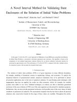
Figure 1.1: Evolution of Mobile Cellular Communications
4
generation (2.5G) technology which is evolved from the existing 2G networks of-
fering enhanced data rate to users while waiting for 3G systems to become mature
to o®er their services. Beyond 3G, 4G systems aim to o®er even higher data rates
with wide area coverage and high mobility. Figure 1.1 shows the progression of the
di®erent generations of mobile cellular communications highlighting the various
standards and some characteristic features.
The boundary between 1G and 2G systems is the analog/digital split. The
2G systems provide low data communication of up to 14.4kbps. Between 2G and
2.5G/3G systems, the main distinction is the much higher data capacity o®ered
by 2.5/3G systems (up to 2Mbps in 3G). We see here a trend for the demand of
higher data rate.
The challenges facing the demand for higher data rate are numerous and com-
plex. Limited bandwidth is one challenge. Bandwidth e±cient modulation schemes
are desirable but they are usually not power e±cient and require coherent demod-
ulation. In the mobile propagation environment, coherent demodulation requires
knowledge of the channel response and this usually entails the insertion of pilot
symbols to estimate the channel response. This consumes bandwidth and avail-
able power. Increasing transmitted power is not the solution in the mobile cellular
communication environment as this would increase the co-channel and adjacent
channel inference experienced by other users. Thus, the overall system throughput
will be limited. The increase in power consumption would also quickly deplete the
battery in the mobile devices.
In response to the severe constraint of bandwidth and power, there is intense
research activity focused on bandwidth e±cient modulation schemes and better
forward error correction codes to combat channel impairments and to improve
system e±ciency. There is also active research in developing optimum channel
estimation algorithms to obtain reliable channel estimates using minimum number
of pilot symbols and without assuming a-priori knowledge of channel response so
as to satisfy the demand for higher system throughput.
5
1.1.1 First Generation (1G) Mobile Communications
The ¯rst generation of mobile cellular communication systems appeared in the
1970s in North America and in the 1980s in Europe. Prior to the cellular systems,
there were already several mobile radio networks. However, they are characterized
by low capacity and mobility compared to the cellular network.
In a cellular network, the coverage area is divided into cells where each cell
corresponds to the coverage area of one transmitter. The transmitter's power level
is just su±cient to cover its own cell. This enables e±cient frequency reuse so that
the same set of frequencies can be reused at some distance away. By reusing the
same frequency again and again, the number of RF channels available to the service
operator increases tremendously. Hence, more users can have access to the service.
Figure 1.2 illustrates the cellular concept. There is no single standard worldwide
but several competing ones. The more successful standards are the Nordic Mobile
Telephone (NMT), the Total Access Communications System (TACS) and the
Advanced Mobile Phone Service (AMPS).
The main purpose of the ¯rst generation system is voice communication. Though
analog cellular systems can send digital messages and provide advanced services
such as short message service, these are limited to very slow data rates. Also, new
features generally require hardware changes to both mobile phones and cellular
networks.
1G systems are also characterized by the use of frequency division multiple
access (FDMA) and analog modulation technique such as frequency modulation
(FM). The main advantage is simplicity in implementation as FDMA/FM is a
proven technology. However, there are several shortcomings of an analog system.
It does not o®er high throughput compared to a digital system. The limited digital
signaling rates limit the ability of analog systems to o®er advanced authentication
techniques and voice encryption services. Hence it is not secure.
The use of analog modulation scheme also does not allow powerful forward
6