Synthesis of ionic liquids and their applications in capillary electrophoresis
Bạn đang xem bản rút gọn của tài liệu. Xem và tải ngay bản đầy đủ của tài liệu tại đây (1.87 MB, 201 trang )
SYNTHESIS OF IONIC LIQUIDS AND THEIR
APPLICATIONS IN CAPILLARY ELECTROPHORESIS
QIN WEIDONG
NATIONAL UNIVERSITY OF SINGAPORE
2003
SYNTHESIS OF IONIC LIQUIDS AND THEIR
APPLICATIONS IN CAPILLARY ELECTROPHORESIS
QIN WEIDONG
(M. Eng., CISRI)
A THESIS SUBMITTED
FOR THE DEGREE OF DOCTOR OF PHILOSOPHY
DEPARTMENT OF CHEMISTRY
NATIONAL UNIVERSITY OF SINGAPORE
2003
ACKNOWLEDGEMENTS
I would like to express my sincere thanks to my supervisor Professor Sam Fong
Yau Li for his invaluable guidance, encouragement, and patience throughout this
work.
Special thanks go to the National University of Singapore for financing of this
work and award of research scholarship.
I would like to thank all of the research staff and students in our laboratory in
particular Mr. Feng Huatao, Ms. Fang Aiping, Ms. Yuan Linlin, Mr. Zhan Wei, Dr.
Wu Yuanshen and Dr. Wang Tianlin for their friendship and assistance. I owe my
special thanks to Dr. Wei Hongping of CE Resources (Singapore) for providing
with me information and comments, many of which have greatly benefited my
research.
I also want to acknowledge the staff of General Office and Chemical Store for their
kind assistance.
LIST OF SYMBOLS AND ABBREVIATIONS
2,4,5-T 2,4,5-Trichlorophenoxyacetic
acid
2,4-D 2,4-Dichlorophenoxyacetic
acid
2,4-DB 4-(2,4-dichlorophenoxy)
butyric acid
2,4-DCBA 2,4-dichlorobenzoic acid
3,5-DCBA 3,5-dichlorobenzoic acid
4-CPA 4-chlorophenoxyacetic acid
α-CD α-Cyclodextrin
A
p
Peak area
BGE Back ground electrolyte
BMIMCl 1-butyl-3-methylimidazolium
chloride
bp Base pairs
C
Concentration
C
18
Octadecylsilane
CE Capillary electrophoresis
CEC Capillary
electrochromatography
CGE Capillary gel electrophoresis
CIEF Capillary isoelectric focusing
CITP Capillary isotachophoresis
CPTCS 3-chloropropyl-
trichlorosilane
CPTMS 3-chloropropyl-
trimethoxysilane
CRM Consecutive reaction
monitoring
CTAC Hexadecyltrimethylammonim
chloride
CZE Capillary zone
electrophoresis
D
Diffusion coefficient
DAIM Dialkylimidazolium
Dichlorprop 2-(2,4-
dichlorophenoxy)propionic
acid
DMIMCl 1-decyl-3-methylimidazolium
chloride
DMSO Dimethyl sulphoxide
E
The electric field strength
ECD Electron capture detection
EMIM 1-ethyl-3-methylimidazolium
ESI Electrospray ionization
F
Faraday’s constant
FAB Fast atom bombardment
FASI Field-amplified sample
injection
FSCE Free solution capillary
electrophoresis
GC Gas chromatography
η
Viscosity
HBMIM 1-(4-hydroxy-butyl)-3-
methylimidazolium
HEC Hydroxyethylcellulose
HMIM 1-hexyl-3-
methylimidazolium
HPLC High-performance liquid
chromatography
I
Ionic strength
I.D. Internal diameter
i
iBMIM 1-isobutyl-3-
methylimidazolium
1-isobutyl-3-
methylimidazolium
IE-OTCEC IE-OTCEC Ion-exchange open tubular
capillary
electrochromatography
Ion-exchange open tubular
capillary
electrochromatography
IL IL Ionic liquid Ionic liquid
ILCC ILCC IL-coated capillary IL-coated capillary
L L
Capillary length Capillary length
LDR LDR Linear dynamic range Linear dynamic range
LIF LIF Laser induced fluorescence Laser induced fluorescence
l
inj
l
Length of the injected plug Length of the injected plug
LOD LOD Limit of detection Limit of detection
MALDI-
MS
MALDI-
MS
Matrix-assisted laser
desorption/ionization mass
spectrometry
Matrix-assisted laser
desorption/ionization mass
spectrometry
Mecoprop Mecoprop 2-(2-Methyl-4-
chlorophenoxy)propanoic
acid
2-(2-Methyl-4-
chlorophenoxy)propanoic
acid
MEKC MEKC Micellar electrokinetic
chromatography
Micellar electrokinetic
chromatography
µ
οε
µ
EOF rate EOF rate
MS MS Mass spectrometry Mass spectrometry
N N
Theoretical plate number Theoretical plate number
NACE NACE Nonaqueous capillary
electrophoresis
Nonaqueous capillary
electrophoresis
PA PA Polyacrylamide Polyacrylamide
PACC PACC PA-coated capillary PA-coated capillary
PEO PEO Poly(ethylene oxide) Poly(ethylene oxide)
PGD PGD Potential gradient detector Potential gradient detector
PVP PVP Polyvinylpyrrolidone Polyvinylpyrrolidone
q q
Number of ionic charges Number of ionic charges
r r
Ionic radius Ionic radius
Capillary internal diameter Capillary internal diameter
Rs Rs
Resolution Resolution
RSD RSD Relatively standard deviation Relatively standard deviation
S/N S/N The signal to noise ratio The signal to noise ratio
σ
A
22
σ
Variance due to wall
adsorption
Variance due to wall
adsorption
σ
D
22
σ
Variance due to longitudinal
diffusion
Variance due to longitudinal
diffusion
SDS SDS Sodium dodecyl sulfate Sodium dodecyl sulfate
σ
E
22
σ
Variance due to
electrophoretic dispersion
Variance due to
electrophoretic dispersion
σ
I
22
σ
Variance due to injection
overloading
Variance due to injection
overloading
σ
J
22
σ
Variance due to Joule heating Variance due to Joule heating
σ
O
22
σ
Variance due to other effects Variance due to other effects
SL
SL
Sildenafil Sildenafil
SPE SPE Solid phase extraction Solid phase extraction
σ
W
22
σ
Variance due to width of the
detection zone
Variance due to width of the
detection zone
T T
Temperature Temperature
TBE TBE Tris-Boric acid-EDTA Tris-Boric acid-EDTA
TIC TIC Total ion chromatogram Total ion chromatogram
t
m
t
Migration time Migration time
TR TR Transfer ratio Transfer ratio
UK UK UK103,320 UK103,320
V V
The applied voltage The applied voltage
v v
Velocity Velocity
VOCs VOCs Volatile organic compounds Volatile organic compounds
z z
Valence of ion Valence of ion
ζ ζ
Zeta potential Zeta potential
Apparent mobility Apparent mobility
Conductivity difference Conductivity difference
Mobility of counterion Mobility of counterion
Pressure difference Pressure difference
inj
οε
A
D
E
I
J
O
W
m
∆
∆
appapp
µ
e
κ
count
µ
P
ii
Conductivities of buffer
Conductivities of sample
solution
Temperature coefficient of
electrophoretic mobility
Difference between
electrophoretic mobilities
Average electrophoretic
mobility
λ
λ
Ω
∆
µ
B
S
T
µ
iii
LIST OF FIGURES
Fig. 1-1 Schematic representation of ionic liquid……………………………………… 2
Fig. 1-2 Diagram of the essential components of a capillary electrophoresis
system………………………………………………………………………… …………9
Fig. 1-3 Schematic representation of migration direction of anion, cation and EOF in a
fused silica capillary 24
Fig. 1-4 Comparison of flow profiles of chromatography and CE…………………26
Fig. 1-5 Schematic illustration showing the mechanism of band broadening due to
electrical conductivity differences between the sample zone and the running buffer.
……………………………………………………………………………………32
Fig. 1-6 Schematic representation of two peaks in electropherogram………………… 38
Fig. 2-1 Schematic representation of synthesis of ionic liquids…………………………47
Fig. 2-2 Mass spectra of HMIMCl (positive ESI) ………………………………….61
Fig. 2-3 Mass spectra of HMIMCl (negative ESI) ……………………………………62
Fig. 2-4 Comparison of Mass spectra of BMIMCl and BMIMPF
6
…………………63
Fig. 2-5 Mass spectra of EMIMCl and EMIMTFMS …………………………………64
Fig. 2-6 MS/MS analysis of [(BMIM)
2
(PF
6
)
3
]
-
…………………………………65
Fig. 2-7 MS/MS analysis of iBMIM …………………………………………………66
Fig. 2-8 Effect of pH on the mobilities of 1-alkyl-3-methylimidazoliums and the simple
imidazoles ……………………………………………………………………………71
Fig. 2-9 Effect of capillary pretreatment …………………………………………73
Fig. 2-10 Chemical structure and schematic model of cyclodextrin ……………………74
Fig. 2-11 Influence of a-CD concentration on the separation of the analytes
……………………………………………………………………………….…76
Fig. 2-12 Electropherogram of commercial chemicals and reaction mixture during
synthesis of BMIMCl. …………………………………………………………………78
Fig. 3-1 Calculated value of TR versus different µ
co-ion
/µ
counterion
and µ
co-ion
/µ
ana
……84
Fig. 3-2 UV absorbance of imidazole and EMIMCl ……………………………………87
Fig. 3-3 Comparison of EMIM and imidazole as background chromophores ……92
Fig. 3-4 Comparison of the calculated and measured mobilities of ions ………….94
Fig. 3-5 Separation of K+ and NH
4
+
in human urine ……………………….…………95
Fig. 4-1 Schematic representation of the IL coating procedure …………………101
Fig. 4-2 Influence of alkylation time and buffer pH on the EOF of CT
110
……… 103
Fig. 4-3 Schematic representation of the CT
210
Surface ………………………… 104
Fig. 4-4 Structure and mass spectra of SL and UK ………………………………… 106
Fig. 4-5 Influence of pH on the CZE performance ……………………………… 111
Fig. 4-6 Influence of injection time …………………………………………………112
Fig. 4-7 Electropherogram of SL and UK in human serum ……… 114
Fig. 4-8 Electropherograms of DNA in ILCC (CT
223
) and PACC ………………… 119
Fig. 4-9 Mobility differences of ssDNA in ILCC (CT
223
) and PACC ………….120
Fig. 4-10 Dependence of DNA-IL interaction on No. of base pairs ………………… 122
Fig. 4-11 Influence of buffer concentration on DNA separation ………………… 124
Fig. 4-12 Influence of electric field strength ………………………………………… 126
Fig. 5-1 Schematic diagrams illustrating the procedures of FASI ………………… 137
Fig. 5-2 Effect of α-CD on mobilities of IL cations ……… 142
Fig. 5-3 Comparison of bare and ILCC (CT
122
) ………………………… 143
Fig. 5-4 Influence of buffer pH on mobilities of ions …………………………………144
Fig. 5-5 Complexing of 18-crown-6 with metal ions and ammonium ………… 145
Fig. 5-6 Effect of 18-crown-6 on the mobilities of ions …………………………146
iv
v
Fig. 5-7 Influence of α-CD on detection sensitivity of ions ……… 147
Fig. 5-8 Electropherogram of ions under FASI mode ………………………… 148
Fig. 5-9 Experimental domain of the face-centered composite design ………… 149
Fig. 5-10 Three-dimensional plots of the response function against pH and concentration
of 18-crown-6 ………………………………………………………………………… 152
Fig. 6-1 Electrophoresis of standard mixtures in buffer without IL …………………164
Fig. 6-2 Representative scheme of the electrophoresis of the analytes under the influence
of the IL additive ………………………………………………………………… 165
Fig. 6-3 Influence of pH ………………………………………………………… 166
Fig. 6-4 Influence of acetonitrile concentration ………………………………… 167
Fig. 6-5 Influence of BMIMPF
6
………………………………………………… 168
Fig. 6-6 Influence of different ILs ………………………………………………… 170
Fig. 6-7 Influence of concentration of sodium sulphate on the recovery of herbicides
…………………………………………………………………………………174
Fig. 6-8 Influence of pH on the recovery ………………………………………… 175
Fig. 6-9 Electropherogram of real sample …………………………………………178
Fig. 6-10 Analysis of the real sample by HPLC …………………………………179
LIST OF TABLES
Table 2-1 Comparison of the yields of DAIM based ILs ……………………………55
Table 2-2 m/z values of the analytes ……………………………………………………58
Table 2-3 LOD, calibration data and precision obtained from the optimized conditions
………………………………………………………………………… 76
Table 3-1 Adjusted mobility of imidazoles and EMIM in buffer of different pH ……89
Table 4-1 Reagents used in the coating procedure ………………………………… 100
Table 4-2 Recovery, repeatability and LOD of the SPE-CZE-MS/MS method … 114
Table 4-3 Comparison of stability and reproducibility of ILCC with PACC ………… 128
Table 5-1 Quantification factors of the CZE-PGD method ………………………….153
Table 6-1 List of the analytes ……………………………………………………….160
Table 6-2 Recoveries of herbicides with different eluents ……………………… 172
Table 6-3 Validation of the SPE-CZE method ………………………………….176
vi
CONTENTS
CHAPTER 1 INTRODUCTION …………………………………………….… 1
1.1 Ionic liquids ……………………………………………………………………1
1.1.1 Use as electrolyte in solar battery ……………………………………….… 2
1.1.2 As solvent for extraction ……………………………………….…… 3
1.1.3 As solvent and catalyst for chemical reaction ………………………….………4
1.1.4 Use in capillary electrophoresis ……………………………………….6
1.2 Capillary electrophoresis … … … … … … … … … … … … . . 7
1.2.1 System and Mechanism … … … … … … … … … … … … … … . … … 9
1.2.2 Operation Modes of CE ……………………………………………………19
1.2.3 Concepts related to CE ……………………………………………………23
1.3 Scope of study ………………………………………………………………….39
References ……………………………………………………………………………41
CHAPTER 2 SYNTHESIS AND TEST OF IONIC LIQUIDS …………….……47
2.1 Chemicals …………………………………………………………….48
2.2 Apparatus ………………………………………………………………48
2.3 Synthesis of ILs ……………………………………………… ………50
2.3.1 1, 3-Dialkylimidazolium (DAIM) halides ……………………………….…50
2.3.2 DAIM tetrafluoroborate ……………………………………………………52
2.3.3 DAIM hexafluorophosphate ……………………………………………………53
2.3.4 DAIM hydroxide ………………………………………………………… 54
2.3.5 Comparison of the yields of the methods ………………………………… 55
2.4 Mass spectrometry study of the ILs ……………………………………………56
2.4.1 Monitoring the IL-cation ………………………………………………58
2.4.2 Association modes of the IL-cations and IL-anions in methanol ………… 58
2.4.3 Identification of species by MS
n
……………………………………………65
2.5 Determination of the impurities in the ILs and the related imidazoles ……68
2.5.1 Dependence of mobilities on pH ………………………………………….70
2.5.2 Composition of the buffer and the buffer concentration ……………………71
2.5.3 Effect of α-CD ……… 73
2.5.4 Linearity, reproducibility and detection limits …………………………76
2.5.5 Applications ……………………………………………………….………77
2.6 Summary …………………………………………………….…… 79
References …………………………………………………………………………81
CHAPTER 3 IONIC LIQUID AS BACKGROUND CHROMOPHORE …… ……82
3.1 Introduction ………………………………………………………………82
3.2 Experimental ………………………………………………………………85
3.2.1 Adjustment of pH and calculation of ionic strength …………………………85
3.2.2 Treatment of urine specimen and stock solutions …………………………86
3.3 Results and Discussion ……………………………………………….86
3.3.1 UV absorbance of imidazolium ………………………………………… 86
3.3.2 Mobility of imidazoles and EMIM ………………………………………….87
3.3.3 Demonstration and application ……………………………………………91
3.4 Summary ……………………………………………………………………95
References ………………………………………………………………………… 96
vii
CHAPTER 4 IONIC LIQUID AS COATING MATERIALS ……………………97
4.1 Materials ……………………………………………………………………98
4.2 Capillary coating ……………………………………………………………99
4.3 EOF of the IL-coated capillary ………………………………………… 102
4.3.1 Influence of pH and reaction time ………………………………………… 102
4.4 Application 1: Separation of sildenafil and its metabolite ………………… 104
4.4.1 Experimental ………………………………………………………………… 108
4.4.2 Results and discussion ………………………………………………… 110
4.5 Application 2: Separation of DNA in ILCC …………………………………115
4.5.1 Introduction ………………………………………………………………… 115
4.5.2 Results and discussion ………………………………………………… 117
4.6 Summary ……………………………………………………………… 128
References ………………………………………………………………………… 131
CHAPTER 5 IONIC LIQUIDS AS BACKGROUND ELECTROLYTE AND
COATING MATERIAL ………………………………………………………… 134
5.1 Introduction ………………………………………………………………… 134
5.2 Experimental ………………………………………………………………… 139
5.2.1 Synthesis of ionic liquids and coating …………………………………139
5.2.2 Sample injection ……………………………………………………… 139
5.3 Results and discussion ………………………………………………… 140
5.3.1 Background co-ion ……………………………………………………… 140
5.3.2 Influence of IL coating ………………………………………………… 142
5.3.3 Effect of buffer pH ………………………………………………………… 144
5.3.4 Effect of 18-crown-6 ……………………………………………………… 145
5.3.5 Effect of α-CD ……………… 146
5.3.6 Effect of FASI …………………………………………………………………147
5.3.7 Optimization of the experimental conditions ………………………………… 149
5.3.8 Quantitations ………………………………………………………………… 152
5.4 Summary …………………………………………………….………… 154
References ………………………………………………………………………… 155
CHAPTER 6 IONIC LIQUIDS AS ADDITIVES …………………………………158
6.1 Introduction ………………………………………………………………… 158
6.2 Experimental ……………………………………………………………… 161
6.2.1 Chemicals and stock solutions ………………………………………… 161
6.2.2 SPE procedure ……………………………………………………………… 162
6.3 CZE method development ………………………………………………… 163
6.3.1 Influence of buffer concentration ………………………………………… 163
6.3.2 Influence of pH ……………………………………………………… 164
6.3.3 Influence of organic solvents ………………………………………………… 166
6.3.4 Influence of additive concentration ………………………………………… 167
6.3.5 Influence of the IL-cation and IL-anion ………………………………… 171
6.4 SPE of the herbicides ………………………………………………………… 171
6.4.1 Eluent and its influence on analysis ………………………… ………………171
6.4.2 Salt-out effect and concentration of sodium sulphate …………………… … 174
6.4.3 Influence of pH ………………………………………………………… 175
6.5 Validation of SPE-CE method ………………………………………… 176
6.6 Real Sample Analysis ………………………………………………………… 177
viii
ix
6.7 Summary ………………………………………………………………… 179
References ……………………………………………………………………….180
CHAPTER 7 CONCLUSION AND FUTURE WORK ………………………… 183
7.1 Conclusion ……………………………………………………………… 183
7.2 Future work ……………………………………………………………… 185
LIST OF PUBLICATIONS ……………………………………………………… 187
SUMMARY
This work focuses on the synthesis of 1,3-dialkylimidazolium based ionic liquids (ILs)
and methods development, optimization and applications of these materials in capillary
electrophoresis (CE).
A series of ILs were synthesized with different methods and their yields were compared.
The properties of the ILs were investigated with mass spectrometry (MS), indicating
their different combining modes in organic solvents which would partially relate to their
behavior in CE. A capillary electrophoresis (CE) method for determining the main
impurity (1-methylimidazole) and by-products during the synthesis was developed with
detection limits as low as 0.42 µg/ml.
The IL-cations are UV active and their electrophoretic mobilities are relatively stable
over a wide pH range, making them suitable as background chromophores in CE.
Research obtained in this study showed that 1-ethyl-3-methylimidazolium (EMIM) was
a good chromophore between pH 3.5 and pH 11.5, while imidazole could only work
below pH 7. Ammonium in human urine was successfully separated from the high-
concentration potassium without additives and determined by CE using EMIM as
background chromophore at pH 8.5.
Research on ILs as coating materials showed that the electroosmotic flow (EOF) of the
capillary was reversed and its magnitude could be controlled by manipulating coating
parameters such as reaction time. The interaction between the cationic analytes and the
silica wall was reduced and hence the peak shapes and the recoveries were improved.
x
xi
With careful design and operation, the co-migrating sildenafil and its metabolite were
baseline separated and determined by CE-mass spectrometry. Application of IL-coated
capillary (ILCC) in DNA separation depicts that in the presence of weak self-coating
sieving matrix hydroxyethylcellulose (HEC), the fragments were separated in similar
patterns as obtained in polyacrylamide-coated capillary with shorter analysis time due
mainly to the anodic EOF. Also, the experimental data indicate electrostatic interaction
between DNA and the cationic coating, which is dependent on the charge density of the
fragments.
Combination of ILs as both background electrolytes and coating materials were
employed in the separation of metal ions. Eleven metal ions were baseline separated in
IL-coated capillary with detection limits as low as 0.27 ng/ml. The detection limits were
lowered by two approaches. First, field-amplified sample injection was employed.
Secondly, the sensitivity of potential gradient detector was improved by reducing the
mobility of the background co-ion, the IL-cation, by addition of α-cyclodextrin (α-CD).
Fast separation of 7 phenoxy and benzoic acid herbicides was accomplished by using IL
as additive. In phosphate-acetate buffer, the EOF of the capillary was reversed with
addition of IL, and the analytes were baseline separated within 7 minutes under negative
voltage. In addition, the resolution of position isomers was significantly improved. A
solid-phase extraction (SPE) procedure was also developed and coupled with the CE
method in the analysis of a local surface water sample for residual herbicides.
Chapter 1
1
CHAPTER 1 INTRODUCTION
1.1 Ionic liquids
The ionic liquids (ILs) are those compounds composed of organic cations and inorganic
or organic anions which are liquids at room temperature or whose melting points are
slightly higher than ambient temperature. The first ambient temperature ionic liquid was
synthesized in 1951 [1], an alkylpyridinium based salt (N-ethylpyridinium bromide-
aluminium chloride). However, it was not until the discovery of the 1,3-
dialkylimidazolium based ionic liquids in 1982 that this group of materials engendered
dramatic interests [2] because the later exhibit both a wide liquidus range and
electrochemical window that are useful in both electrochemistry and synthesis;
moreover, the dialkylimidazolium based ILs are more stable [3]. Investigations have
been carried out mainly on this group of compounds from then on. Low melting point
ILs typically exhibit mixed organic and inorganic character. The cation containing
imidazole ring and attached alkyl groups is relatively large compared to simple
inorganic cations, accounting for the low melting point of the salt. The chemical
property of the IL is determined prominently by the anion.
The research in this thesis is focused on applications of the 1,3-dialkylimidazolium
based ILs. The terms “ionic liquid”, “IL”, “dialkylimidazolium based IL” and “ILs” in
the thesis are related to the same group of ILs.
Chapter 1
2
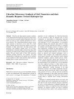
NN
R
1
+
R
2
X
-
X
can be Cl ,Br , BF
4
, PF
6
, etc
-
-
-
Fig. 1-1 Schematic representation of ionic liquid
Fig. 1-1 shows the schematic representation of the 1,3-dialkylimidazolium based IL.
Generally R
1
and R
2
are alkyl groups as reported in many publications [3-5], but
actually they can be any groups that can be added onto the imidazole ring via chemical
reaction. Halides are the primary ILs synthesized, and are usually the beginning
materials for other ILs. Tetrafluoroborate and hexafluorophosphate have drawn
enormous interests owing to their feasibilities as electrolyte in solar battery and as
solvents for liquid-liquid extraction. The following is the brief introduction of
applications of this kind of materials. Although some of the applications are still
potential, IL has shown promise.
1.1.1 Use as electrolyte in solar battery
The electrolytes used in many conventional solar cells are salts dissolved in organic
solvents. There are some drawbacks with the electrolytes used: 1) because the organic
solvents are volatile, the cell must be absolutely tight, leading to high cost; moreover,
the life time of the cell is influenced by the leakage of the solvents [5]; 2) when the cell
works at lower temperature than anticipated, the salts may precipitate out due to the
reduced solubility. 3) The organic solvents are often incompatible with the glues used to
Chapter 1
3
seal the cell. 4) For the dye-sensitized nanocrystalline solar cell, UV exciting of the dye-
supporting semiconductor may cause oxidization of the salts [3].
ILs are liquids that are composed entirely of ions with negligible vapor pressure. But
unlike the normal salts, they are liquids with wide liquidus range and are non-corrosive.
They can be utilized in a wide range of electrochemical applications where high
conductivity and ionic mobility are required. These properties as well as relatively low
viscosity, the large electrochemical window, resistance to oxidation, low melting point,
thermal stability, miscibility with other solvents or salts and hydrophobicity are the
desirable qualities rendering them attractive alternatives for use as electrolytes and
solvents in the solar cell. Furthermore, ILs are now appear to be undemanding and
inexpensive to prepare. One of the ILs, 1-hexyl-3-methylimidazolium iodide, has been
found to be of lowest viscosity at room temperature, not sensitive to water, and stable
under the operational conditions of the photoelectrochemical cell utilizing the
iodide/triiodide couple as redox mediator [5].
1.1.2 As solvent for extraction
Liquid-liquid extraction has been a widely used technique in separation science.
However, the traditional solvent extraction, in which an organic solvent and an aqueous
solution were used as the two immiscible phases, is increasingly challenged by the
emphasis on clean manufacturing processes and environmentally benign technologies
because it employs toxic, flammable, volatile organic compounds as solvents. The costs
of solvents are high and disposal of spent extractants and diluents will also bring
increasing costs through the impact of environmental protection regulations. A report
Chapter 1
4
stated that the current worldwide usage of these organic materials has been estimated at
over 5 billion dollars per annum [5]; these organics will have profound influence on
environment and human health. Design of safe and clean separation media is now
becoming an increasingly important role in the development of clean manufacturing
processes.
The ILs used for liquid-liquid extraction are water and air stable; they have relatively
favorable viscosity and density characteristics; they have high solubility in organic
species while the water immiscible ionic liquids are also available. Water immiscible
ILs may render such systems as being uniquely suited to the development of completely
novel liquid-liquid extraction processes. The most important feature of the ILs for these
purposes may be their very low vapor pressure due to the high coulombic forces present
among the ions. With ionic liquids, one does not have the concerns as with volatile
organic solvents. In addition, the R
1
and R
2
groups of the cation (Fig. 1-1) are variable
and may be used to finely tune the properties of the IL. It was reported that such ionic
liquids are able to solvate a wide range of species including organic, inorganic and
organometallic compounds [6].
1.1.3 As solvent and catalyst for chemical reaction
Research was carried out in the early 1980s on IL feasibility as reaction media and it has
attracted industrial interest from late 1990s.
Chapter 1
5
Industrial chemical syntheses usually take place in liquid media, so the solvent
properties play an important role in the reaction. Most chemical synthesis are catalyzed
for the following reasons: 1) greater reaction selectivity and therefore less by-products;
2) enhanced reaction rates which means reduced plant size and hence the costs; 3)
milder operating conditions (in terms of temperature and pressure) due to highly
efficient catalysts, which may lead to both reduced energy consumption and enhanced
safety. There are two factors determining the catalysis effects, one is the active site of
the catalyst, another is the concentration of the catalyst. But classical solvent-catalysts
system usually cannot simultaneously satisfy both the two requirements. For example,
some metal-complex catalysts have to be dissolved in polar solvents in order to achieve
the higher concentration. But the polar solvent often coordinates onto the active site of
the catalyst and consequently blocks it.
Ionic liquids offer a highly polar but noncoordinating environment for chemical
reactions. They can dissolve the metal complex catalyst to a high concentration while
not blocking the active sites. Most of the known transition metal-catalyzed reactions can
be carried out in ionic liquids. These include alkylation, acylation, reduction [7],
oxidation, oligomerization, Diels-alder reaction [8,9] and polymerization [10-14].
Moreover, the solvation and solvolysis phenomena which occur in conventional
solvents can be effectively suppressed in IL-media and therefore, waste production
through side reactions are reduced to a minimum [5,15,16].
The ILs’ wide liquid range is also an amazing parameter for chemical engineering. For
chemical reactions, the higher the reaction temperature, the higher the reaction speed. It
is important for the solvents to be in liquid state so that the reaction can take place
Chapter 1
6
successfully. However, liquid ranges of most organic solvents are usually less than
100°C. As reported [4], some ILs have a liquid range of about 300°C (e.g. 1-ethyl-3
methylimidazolium chloride-aluminum chloride, the archetypal IL, is liquid and
thermally stable from almost –100 to 200 °C), far in excess of the 100°C range for water
or 44°C degree for ammonia.
In some cases, the ILs act as both solvents and catalysts for chemical reactions, for
example, the 1-ethyl-3-methylimidazolium aluminum chloride (EMIMCl·AlCl
3
) system
can be used as a solvent and catalyst for Frieldel-Crafts reactions. A typical Friedel-
Crafts reaction takes six or seven hours to produce about 80% yield of an isomer
mixture; while in an IL, the reaction is complete in about 30 seconds with nearly 100%
conversion [17]. Furthermore, the chemical properties of the IL such as complexing
ability and acidity can be tuned at will.
The following characters of ILs also contribute to their ability as solvent for chemical
reactions: very low vapor pressure, high heat conductivity, stable toward various
organic chemicals, controlled miscibility with organic compounds, easy to separate
from a large range of organic products, tunable Lewis acidity (for EMIMCl·AlCl
3
system), compatible with organometallics, and adjustable coordinating ability.
1.1.4 Use in capillary electrophoresis
With the increasing interests with this kind of new materials, some analysts expanded
the application of ILs to capillary electrophoresis (CE). In the works of Vaher et al
Chapter 1
7
[18], it was employed as electrolytes in nonaqueous capillary electrophoresis (NACE)
for separation of water-insoluble dyes. Recently they also published a paper on the
separation of phenolic mixture with NACE [19]. It was found that the EOF of the
capillary was efficiently reversed, comparable to that of alkaline aqueous buffer in
magnitude with addition of 4 mM IL in pure acetonitrile. Also, the ILs showed
significant resolving ability towards position isomers: the peaks of resorcinol and
pyrocatechol were baseline resolved in the presence of 1.3 mM 1-ethyl-3-
methylimidazolium fluoroacetate. Stalcup and co-workers [20] used ILs as electrolytes
in aqueous capillary electrophoresis for separation of phenolic compounds extracted
from grape. They found that EOF of the capillary was reversed by adsorption of the IL
cations onto the silica wall, and the magnitude of the anodic EOF increased with the
amount of IL added. The neutral analytes were separated based on their different
interaction abilities with dialkylimidazolium. Interestingly, they also found superior
resolution ability of IL (1-butyl-3-methylimidazolium tetrafluoroborate) toward the
mixtures. However, there is to date no reported systematic study of the application of
ILs in this emerging area.
1.2 Capillary electrophoresis
There has been tremendous growth of capillary electrophoresis (CE) in the past decades
since the launch of the first commercial CE instrument in 1989. CE is characterized by
the use of narrow bore capillaries, usually in the range of 10-100 µm internal diameter
(I.D.); operated at high applied potential (Normally less than 30 kV, but recently higher
voltage, up to half million was utilized [21]). CE has notable advantages over the
Chapter 1
8
previous methods in high separation efficiency: short analysis time, and low sample
consumption. Nowadays it is widely used in analytical laboratories.
The separation mechanism of CE is based on the differences in mobilities of species
(either caused by the different electrophoretic mobilities or by their different partition
abilities between the aqueous buffer and the other phase) in small capillaries. The
pioneering work of Hjerten [22] demonstrated the separation of inorganic and organic
ions, peptides, proteins, and bacteria in a tube of 3mm I.D. in 1967. He termed it as free
solution electrophoresis. But due to overloading of the samples, the high efficiencies of
the technique were unable to obtained. By using capillaries of 200 µm I.D., plate
heights smaller than 10 µm were obtained in the work of Mikkers et al [23].
The most widely accepted initial demonstration of the power of CE was carried out by
Jorgenson and Lukacs [24]. Their paper included a brief discussion of simple theory of
dispersion in CE and provided the first demonstration of high separation efficiency with
high field strength in narrow capillaries. Applications also include the separation of
protein and peptides, tryptic mapping, DNA sequencing, serum analysis, analysis of
neurotransmitters in single cells and chiral separations. The technique provides
efficiencies up to two orders greater than high-performance liquid chromatography
(HPLC). With the more and more sophisticated instruments commercially available
since the beginning of 1990s, CE is now gaining popularity, not only as an alternative
analytical tool for some routine analytical application, but also a promising technique in
some modern field.
Chapter 1
9
1.2.1 System and Mechanism
1.2.1.1 System setup
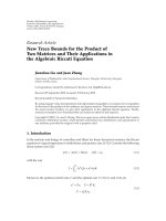
Fig. 1-2 Diagram of the essential components of a capillary electrophoresis system
A typical CE apparatus is shown in
Fig. 1-2. It consists of a high-voltage power supply,
two buffer reservoirs, a capillary and a detector. Separations are carried out in a
capillary tube whose length differs in the range of 20 to 100 cm. The capillary is filled
with running buffer and the sample is introduced by dipping one end into the sample
and applying an electric field (electrokinetic injection) or by applying gas pressure
(hydrodynamic injection) or by gravity. Migration through the capillary is driven by an
electric field, and analytes are detected as they pass the window at the far end. The
signal from the detector is usually sent to an integrator or recorder; but nowadays more
and more computers are used in data acquisition, the electropherograms are saved
digitally and the separation performance and quantification are evaluated by
Chapter 1
10
professional software. Further, the computer-interfaced CE system can usually be
operated under automated mode, which is helpful in improving reproducibility of the
operation favoring its application in industrial analysis.
1.2.1.2 Capillary
The capillary is the crucial part of the CE system; they can be differentiated by
dimensions, shapes and materials. The dimensions (length and radius) are important for
the electric field and the heat dissipation as will be discussed. The capillary material is
important for successful separation since it determines parameters such as magnitude
and direction of EOF, heat dissipation and wall-analyte interaction. By far, fused silica
has been the material of choice for its superior characteristics compared to other
materials, including optical transparency across the UV and visible regions, high
thermal conductance, mechanical stability when coated with polyimide and feasibility
of manufacture with inner diameters down to a few microns.
Efforts were also made using polymeric materials as alternatives by many authors.
Polymeric materials such as polyester (PE), polyurethane (PU), polypropylene (PP),
polymethylmethacrylate (PMMA), ethylene vinylacetate (EVA) and others have been
tested and used for CE separations [25-27]. Although the polymer hollow fibers also
exhibit cathodic EOF as in fused silica capillaries, it is lower [25]. Because all polymer
materials have their own physical and chemical properties, the quality of separations
and selectivities may differ from one to another. But in general because their low heat
conductivity, they are not good at dissipating heat and hence the separation voltage is
lower compared to that across fused silica capillary, leading to long analysis time, low
efficiency and even poor reproducibility. Other disadvantages of using these polymer
Chapter 1
11
materials as separation capillary also include UV absorbance and hydrophobic
interactions of the capillary with analytes which may cause significant adsorption
problems. The advantage of using the polymer capillaries lies in the ease of preparing
dynamic or permanent capillary coatings for a particular separation [27,28].
1.2.1.3 Migration of ions under electric field
Under the influence of an applied electric field, sample ions will move towards their
appropriate electrode; cations move towards the cathode and anions towards the anode.
When a particle moves in a solution, it also experiences a frictional retarding force that
is proportional to its velocity and the solution viscosity. Its migration speed is such
determined that the electric driving force is in magnitude equal to frictional retarding
force. So the speed of their movement towards the electrode is governed by their size,
charge state and the properties of the solution as well. Smaller molecules with a large
number of charges will move more quickly than larger or less charged compounds. The
electrophoretic mobility
ep
µ
is theoretically expressed as
r
q
ep
πη
µ
6
=
(1-1)
where, q is the number of ionic charges,
η
is the solution viscosity and r the
hydrodynamic radius.
The velocity of a particle is linked to its electrophoretic mobility by
L
V
Ev
epepep
µµ
==
(1-2)