Singularity analysis and handling towards mobile manipulation
Bạn đang xem bản rút gọn của tài liệu. Xem và tải ngay bản đầy đủ của tài liệu tại đây (7.47 MB, 205 trang )
SINGULARITY ANALYSIS AND
HANDLING TOWARDS MOBILE
MANIPULATION
DENNY NURJANTO OETOMO
B.Eng
A DISSERTATION SUBMITTED
FOR THE DEGREE OF DOCTOR OF PHILOSOPHY
DEPARTMENT OF MECHANICAL ENGINEERING
NATIONAL UNIVERSITY OF SINGAPORE
2004
ACKNOWLEDGMENTS
I would like to express my gratitude to my supervisor, Associate Professor Marcelo
H. Ang Jr., for all the guidance and support beyond academic aspects, throughout my
period of candidature. Also to Professor Oussama Khatib from Stanford University,
for his guidance and inspiration. I would also like to thank Dr. Lim Ser Yong from the
Singapore Institute of Manufacturing Technology and my panel of advisors: Asso ciate
Professor Teo Chee Leong and Assistant Professor Etienne Burdet from the National
University of Singapore. Also to my fellow members of the project U98A031 of the
Singapore Institute of Manufacturing Technology: Rodrigo Jamisola, the father of my
goddaughter Maanyag, for helping me get started in robotics when I first joined the
project and for all the help from the start till the end of the project, Mana Saedan,
who was also my flatmate, for his help and his cool handling of even the worst crises,
Lim Tao Ming, the computer authority in the lab, for all the help from writing codes
to troubleshooting the Sensable PHANToM haptic device, Lim Chee Wang, who is
always ready to help, especially in mobile base issues. Not to forget Liaw Hwee Choo
for the fundamental work in dynamics and help in machine maintenance, and Leow
Yong Peng, who was a lot of help in kinematic analysis of wheel modules, a great
source of advice and, most important of all, for introducing me to L
A
T
E
X. Last but
not the least, my parents for everything I have, and my wife, Lois, for her support
and encouragement in everything I strive to achieve in life.
ii
TABLE OF CONTENTS
Page
Acknowledgments . . . . . . . . . . . . . . . . . . . . . . . . . . . . . . . . . . ii
Summary . . . . . . . . . . . . . . . . . . . . . . . . . . . . . . . . . . . . . . x
Nomenclature . . . . . . . . . . . . . . . . . . . . . . . . . . . . . . . . . . . . xii
List of Tables . . . . . . . . . . . . . . . . . . . . . . . . . . . . . . . . . . . . xiv
List of Figures . . . . . . . . . . . . . . . . . . . . . . . . . . . . . . . . . . . xv
Chapters:
1. Introduction . . . . . . . . . . . . . . . . . . . . . . . . . . . . . . . . . . 1
2. Background Theory I: Force and Motion Control of Manipulators . . . . 7
2.1 Chapter Overview . . . . . . . . . . . . . . . . . . . . . . . . . . . 7
2.2 Operational Space Formulation . . . . . . . . . . . . . . . . . . . . 7
2.2.1 Motion Control . . . . . . . . . . . . . . . . . . . . . . . . . 9
iii
2.2.2 Force Control . . . . . . . . . . . . . . . . . . . . . . . . . . 10
2.2.3 Unified Force and Motion Control . . . . . . . . . . . . . . 11
2.3 Decoupling of the Jacobian Matrix . . . . . . . . . . . . . . . . . . 15
2.4 Redundancy . . . . . . . . . . . . . . . . . . . . . . . . . . . . . . . 18
2.4.1 Redundancy Definition . . . . . . . . . . . . . . . . . . . . . 18
2.4.2 The Jacobian Matrix . . . . . . . . . . . . . . . . . . . . . . 19
2.4.3 Redundancy Resolution . . . . . . . . . . . . . . . . . . . . 19
2.4.4 When Null Space Projection Conflicts with End-Effector Mo-
tion . . . . . . . . . . . . . . . . . . . . . . . . . . . . . . . 23
2.5 Generalised Inverses . . . . . . . . . . . . . . . . . . . . . . . . . . 25
2.5.1 Dynamically Consistent Inverse . . . . . . . . . . . . . . . . 26
2.6 Measure of Orientation Error . . . . . . . . . . . . . . . . . . . . . 28
3. Background Theory II: Singularities . . . . . . . . . . . . . . . . . . . . . 29
3.1 Types of Singularities . . . . . . . . . . . . . . . . . . . . . . . . . 29
3.1.1 Real singularity . . . . . . . . . . . . . . . . . . . . . . . . . 29
3.1.2 Artificial singularity . . . . . . . . . . . . . . . . . . . . . . 30
3.2 Kinematic Singularity . . . . . . . . . . . . . . . . . . . . . . . . . 30
3.2.1 A Two-link Example of Singularity . . . . . . . . . . . . . . 30
3.2.2 Singular Value Decomposition . . . . . . . . . . . . . . . . . 32
3.3 Semi Singularity . . . . . . . . . . . . . . . . . . . . . . . . . . . . 34
3.4 Algorithmic Singularity . . . . . . . . . . . . . . . . . . . . . . . . 35
3.4.1 Example with Extended Jacobian Matrix method . . . . . . 35
3.4.2 Example:Mobile Bases with Powered Caster Wheel . . . . . 36
iv
3.5 Semi-Algorithmic Singularity . . . . . . . . . . . . . . . . . . . . . 41
3.6 Summary . . . . . . . . . . . . . . . . . . . . . . . . . . . . . . . . 41
4. New Insights into the Identification of Kinematic Singularities and its De-
generate Directions . . . . . . . . . . . . . . . . . . . . . . . . . . . . . . 43
4.1 Chapter Overview . . . . . . . . . . . . . . . . . . . . . . . . . . . 43
4.2 Introduction and Background . . . . . . . . . . . . . . . . . . . . . 44
4.3 Singularity Identification for a 6 DoF Manipulator . . . . . . . . . 45
4.3.1 Singularity Identification in PUMA . . . . . . . . . . . . . . 45
4.4 Singularity Identification for Redundant Manipulator . . . . . . . . 46
4.4.1 Separating Jacobian into Position and Orientation . . . . . 47
4.4.2 Utilising the Minors of the Jacobian Matrix . . . . . . . . . 47
4.4.3 Example: Mitsubishi PA-10 (7 DoF Articulated Robot) . . 48
4.4.4 Summary of singularities in PA-10 . . . . . . . . . . . . . . 52
4.5 Completeness of Solution . . . . . . . . . . . . . . . . . . . . . . . 52
4.6 Identifying the Singular Direction . . . . . . . . . . . . . . . . . . . 58
4.6.1 Head Lock . . . . . . . . . . . . . . . . . . . . . . . . . . . 59
4.6.2 Elbow lock . . . . . . . . . . . . . . . . . . . . . . . . . . . 60
4.6.3 Wrist lock . . . . . . . . . . . . . . . . . . . . . . . . . . . . 61
4.6.4 On Whether There is Always a Zero Row . . . . . . . . . . 62
4.6.5 On Identification of Singular Direction . . . . . . . . . . . . 64
4.6.6 Singular Value Decomposition in Determining Singular Di-
rections . . . . . . . . . . . . . . . . . . . . . . . . . . . . . 65
v
4.6.7 Families of Singularities with Additional Singular Direction:
Mitsubishi PA-10 . . . . . . . . . . . . . . . . . . . . . . . . 69
4.7 A Simple Check to the Complete Set of Solution to Singular Config-
urations of Redundant Manipulator . . . . . . . . . . . . . . . . . . 71
4.8 Summary . . . . . . . . . . . . . . . . . . . . . . . . . . . . . . . . 75
5. Singularity Handling: by Removal of Degenerate Components . . . . . . 76
5.1 Chapter Overview . . . . . . . . . . . . . . . . . . . . . . . . . . . 76
5.2 Related Works . . . . . . . . . . . . . . . . . . . . . . . . . . . . . 77
5.3 Handling Singularity by Removing Degenerate Components . . . . 80
5.3.1 The Singular Region . . . . . . . . . . . . . . . . . . . . . . 80
5.3.2 Removing Degenerate Components . . . . . . . . . . . . . . 81
5.3.3 Utilising the SVD . . . . . . . . . . . . . . . . . . . . . . . 82
5.3.4 Null Space Control . . . . . . . . . . . . . . . . . . . . . . . 82
5.4 Application on PUMA Robot . . . . . . . . . . . . . . . . . . . . . 84
5.4.1 Removing the Degenerate Components . . . . . . . . . . . . 84
5.4.2 The Use of Singular Value Decomposition . . . . . . . . . . 86
5.4.3 The Use of Null Motion . . . . . . . . . . . . . . . . . . . . 87
5.5 Implementation Result . . . . . . . . . . . . . . . . . . . . . . . . . 93
5.6 Summary . . . . . . . . . . . . . . . . . . . . . . . . . . . . . . . . 95
6. The Reduced DOF within Singular Region and Discontinuity Issues Across
the Boundary . . . . . . . . . . . . . . . . . . . . . . . . . . . . . . . . . 101
vi
6.1 Chapter Overview . . . . . . . . . . . . . . . . . . . . . . . . . . . 101
6.2 Introduction . . . . . . . . . . . . . . . . . . . . . . . . . . . . . . 102
6.3 Effects of Removal of Singular Direction . . . . . . . . . . . . . . . 103
6.3.1 Upon entry into the singular region . . . . . . . . . . . . . . 103
6.3.2 Motion in singular region . . . . . . . . . . . . . . . . . . . 104
6.3.3 Exiting the Singular Region . . . . . . . . . . . . . . . . . . 105
6.4 Implementation on PUMA560 . . . . . . . . . . . . . . . . . . . . . 109
6.4.1 Wrist Singularity . . . . . . . . . . . . . . . . . . . . . . . . 110
6.4.2 Elbow Singularity . . . . . . . . . . . . . . . . . . . . . . . 113
6.5 Conclusion . . . . . . . . . . . . . . . . . . . . . . . . . . . . . . . 115
7. Singularity Handling: by Virtual Joints . . . . . . . . . . . . . . . . . . . 117
7.1 Chapter Overview . . . . . . . . . . . . . . . . . . . . . . . . . . . 117
7.2 Introduction . . . . . . . . . . . . . . . . . . . . . . . . . . . . . . 117
7.3 Virtual Joints . . . . . . . . . . . . . . . . . . . . . . . . . . . . . . 118
7.3.1 Supplying Virtual Joints . . . . . . . . . . . . . . . . . . . . 119
7.3.2 Avoiding Assignment of Command to Virtual Joints . . . . 122
7.3.3 Inclusion of Dynamic Model for Torque Control . . . . . . . 126
7.3.4 Effect of Simulated Joint Feedback . . . . . . . . . . . . . . 129
7.3.5 In Singular Configuration . . . . . . . . . . . . . . . . . . . 131
7.4 Application on PUMA robot: the method of virtual joint . . . . . . 132
7.5 Implementation Result on PUMA: by virtual joint . . . . . . . . . 136
7.5.1 Motion through Singular Configuration . . . . . . . . . . . . 136
7.5.2 Non-singular motion . . . . . . . . . . . . . . . . . . . . . . 140
vii
7.6 Conclusion . . . . . . . . . . . . . . . . . . . . . . . . . . . . . . . 141
8. Arm-Base Integration Towards Mobile Manipulation . . . . . . . . . . . 145
8.1 Chapter Overview . . . . . . . . . . . . . . . . . . . . . . . . . . . 145
8.2 Integration of Torque Controlled Arm and Velocity Controlled Base 146
8.2.1 Combined Torque and Velocity Control for the Overall System148
8.3 Application to Aircraft Canopy Polishing . . . . . . . . . . . . . . 150
8.4 On the Issue of Singularity Handling . . . . . . . . . . . . . . . . . 152
8.4.1 Position Singularity . . . . . . . . . . . . . . . . . . . . . . 152
8.4.2 Orientation Singularity . . . . . . . . . . . . . . . . . . . . 153
8.5 Experimental Setup and Result . . . . . . . . . . . . . . . . . . . . 154
8.5.1 Free motion . . . . . . . . . . . . . . . . . . . . . . . . . . . 155
8.5.2 Constrained motion . . . . . . . . . . . . . . . . . . . . . . 158
8.5.3 Canopy polishing . . . . . . . . . . . . . . . . . . . . . . . . 159
8.6 Conclusion . . . . . . . . . . . . . . . . . . . . . . . . . . . . . . . 161
9. Conclusion . . . . . . . . . . . . . . . . . . . . . . . . . . . . . . . . . . . 163
Appendices:
A. Frame Assignments . . . . . . . . . . . . . . . . . . . . . . . . . . . . . . 166
A.1 Frame Assignment for PUMA (stand-alone) . . . . . . . . . . . . . 166
A.2 Frame Assignment for PUMA-NOMAD system . . . . . . . . . . . 167
viii
B. Jacobian Matrix . . . . . . . . . . . . . . . . . . . . . . . . . . . . . . . 169
B.1 Jacobian Matrix for PUMA (stand-alone) . . . . . . . . . . . . . . 169
B.2 Jacobian Matrix for Example Manipulator in Section 3.2.1 . . . . . 170
B.3 Jacobian Matrix for PUMA-NOMAD System . . . . . . . . . . . . 171
Bibliography . . . . . . . . . . . . . . . . . . . . . . . . . . . . . . . . . . . . 173
ix
SUMMARY
Topics covered in this dissertation fall mainly in the general framework of Mobile
Manipulation. A control algorithm that is capable of a unified force and motion
control, based on the Operational Space Formulation [1], was set as the starting
platform in the project.
The thesis focused on the problem of singularity. Issues in identification of sin-
gularities and singular directions were discussed. These issues are not new, however,
certain simplification process is often introduced to reduce the complexity of the iden-
tification techniques. Analysis was performed on these simplified methods to evaluate
the completeness of resulting solutions.
Two concepts of singularity handling methods were presented. The first was
by removing the degenerate components of the task. Certain discontinuity issues
associated with this method were analyzed. This method belongs to the category
that introduces a division in workspace. The second was to supplement the DOFs
lost in singularity with extra “virtual” joints. There is no division of workspace in
this category.
The last chapter presents the example of the application of the operational space
formulation with singularity compensation, performing an industrial task of polishing
the curved surface of an aircraft canopy with no prior knowledge of the surface profile.
x
The workspace of the manipulator was extended by mounting it on a mobile base.
The result is presented in graphs and in videos that are available on the Internet.
xi
NOMENCLATURE
i
J Jacobian matrix expressed in Frame i
A
R
B
3×3 rotation matrix describing the orientation of Frame{B}
in Frame{A}. The 1
st
, 2
nd
, and 3
rd
column represent the
rotation of X, Y, Z axes of Frame{B}expressed in Frame{A}
τ
τ
τ Torque command vector to the manipulator joints
τ
τ
τ
0
Torque command vector to be projected into the null space
of the Jacobian of the manipulator
f Operational space force command vector of the operational
point in a manipulator
A Joint space inertia matrix
B Coriolis and Centrifugal force in joint space
g Gravity vector in joint space
ˆ
Λ Inertia matrix in operational space
µ
µ
µ The Coriolis and centrifugal forces in operational space
p Gravitational vector in operational space
Ω Task specification matrix, on which axes are in force and
which in motion control
J
#
Generalised inverse of a Jacobian matrix
¯
J Dynamically Consistent Inverse of a Jacobian matrix
xii
s
i
sin(q
i
)
c
ab
cos(q
a
+ q
b
)
J
V
Top half of Jacobian matrix J, mapping joint rate to task
space velocity of the operational point
J
ω
Bottom half of Jacobian matrix J, mapping joint rate to
the angular velocity of the operational point.
M
i
The i − th minor of a matrix
s(q) The factor in determinant of the Jacobian matrix which is
zero at specific singularity
s
0
The threshold value that defines the singular region
−∇v
0
(q) Gradient descent of p otential function v
0
(q)
s
1
, s
2
, s
3
Columns of the rotation matrix which represent the orien-
tation of each axis of the end-effector with respect to Base
Frame
s
1d
, s
2d
, s
3d
represent the desired values of s
1
, s
2
, and s
3
{A} Frame {A} as a label in the diagram.
A skew symmetric matrix equivalent to a cross product oper-
ator, see Section 2.3.
a Scalar variable a (lower case, regular font).
a Vector a (lower case, bold font).
A Matrix A (upper case, bold font).
f(q,
˙
q) Function f, a function of q and
˙
q.
xiii
LIST OF TABLES
Table Page
2.1 The position/force duality . . . . . . . . . . . . . . . . . . . . . . . . 20
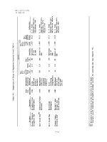
4.1 This table shows which terms in the determinants of the minors set
M
1
to M
4
to zero. . . . . . . . . . . . . . . . . . . . . . . . . . . . . . 51
4.2 Singular directions of Mitsubishi PA-10 at singular configurations where
q
4
= 0 . . . . . . . . . . . . . . . . . . . . . . . . . . . . . . . . . . . 70
5.1 Singularity by the effect of null space torque have on it . . . . . . . . 84
8.1 The position/force duality (reproduced) . . . . . . . . . . . . . . . . . 149
A.1 The modified DH parameters for PUMA manipulator (stand-alone as
in [2] . . . . . . . . . . . . . . . . . . . . . . . . . . . . . . . . . . . . 167
A.2 The modified DH parameters for PUMA mounted on Nomad mobile
bases system . . . . . . . . . . . . . . . . . . . . . . . . . . . . . . . . 167
xiv
LIST OF FIGURES
Figure Page
1.1 Honda Asimo - an example of the recent development in the front
of humanoid robots, spearheaded mainly by the Japanese. (From
. . . . . . . . . . . . . . . . . . . 1
2.1 Tool frame assignment . . . . . . . . . . . . . . . . . . . . . . . . . . 12
2.2 The schematic diagram of the operational space formulation . . . . . 14
2.3 When its operating point is extended from the wrist point (W) to the
tool point (T), a simple transformation matrix can be defined to relate
the Jacobian matrices at the wrist point and the tool point. . . . . . 16
2.4 The relationship between the manipulable and redundant space . . . 18
xv
2.5 The three-link planar (R-R-R) manipulator above is given a task of
following a trajectory in 2D. The extra degree of freedom is assigned
to the null space behaviour of keeping q
2
= −30
0
. The desired end-
effector motion is to move along the X
0
axis away from the origin.
The top and middle pictures show the possible configurations where
both the desired end-effector motion and required null space behaviour
are satisfied. The bottom picture shows the configuration where the
null space behaviour can no longer be satisfied. Notice the (I − J
#
J)
projection matrices for all the three cases. . . . . . . . . . . . . . . . 24
3.1 Example of singular configuration: a two-link planar manipulator has
2 degrees of freedom (left). At singular configuration (right), any joint
command sent to joint 1 and/or joint 2 will not produce any instanta-
neous motion in X
2
direction. . . . . . . . . . . . . . . . . . . . . . . 31
3.2 The powered caster wheel - with three angular velocities, two of which
are measurable and actuated with motors, while ˙σ is not measurable
nor actuated. . . . . . . . . . . . . . . . . . . . . . . . . . . . . . . . 37
3.3 The variables used to describ e the configuration of the mobile base. . 38
xvi
3.4 The singular configurations of a three wheeled mobile base, assuming
active joint commands are: φ
1
(steering angle of wheel 1), ρ
2
and ρ
3
(driving angles of wheels 2 and 3). In (a) the mobile platform cannot
rotate in around its Z axis and (b) it cannot translate in the direction
perpendicular to the parallel lines. . . . . . . . . . . . . . . . . . . . . 40
4.1 Seven dof Mitsubishi PA-10 and its frame assignment . . . . . . . . . 49
4.2 The wrist singularity expressed in Frame 4. It is not able to translate
in Y and rotate in X axis of Frame 4 simultaneously. . . . . . . . . . 55
4.3 The structure of a PUMA manipulator (left) and an example of a 7
DoF PUMA-like manipulator with spherical wrist (right). . . . . . . . 56
4.4 The 7DOF manipulator, side view (planar). The wrist is straightened
(q
6
= 0) with q
5
= 0. It is not able to rotate around axis X
5
. . . . . . 57
4.5 PUMA, from top view, shows the degenerate direction at elbow singu-
larity, expressed in Frame{B}, which is derived from rotating Frame{2}
by angle {b} . . . . . . . . . . . . . . . . . . . . . . . . . . . . . . . . 61
4.6 The wrist of PUMA 560, showing F rame{4} . . . . . . . . . . . . . . 62
xvii
4.7 The singular vectors which form the columns of matrix U and V in
the SVD of the Jacobian matrix in the example. . . . . . . . . . . . . 66
4.8 Mitsubishi PA-10 in singular configurations: left in internal singularity
and right when the arm and the wrist are straightened, where the
manipulator loses 3 DOFs . . . . . . . . . . . . . . . . . . . . . . . . 71
5.1 A two-link planar manipulator is a type 1 singular configuration. . . . 88
5.2 The two link manipulator from the previous example, moving out of
singularity, due to the application of null space motion. . . . . . . . . 89
5.3 shows Puma-like manipulator moving out of elbow (and wrist) singu-
larity, following the path which lies in the degenerate direction . . . . 90
5.4 The value of s(q) = d
4
c
3
− a
3
s
3
as a function of q
3
and 1/s(q ). . . . . 91
5.5 The wrist of PUMA 560, showing F rame{4} . . . . . . . . . . . . . . 92
5.6 Null space torque is used to turn joint 4, so that the YZ plane of
F rame{4} is shifted out of the way of the desired trajectory. . . . . . 92
5.7 Trajectory tracking error of end-effector position as it traces a desired
path that is not singular. . . . . . . . . . . . . . . . . . . . . . . . . . 96
xviii
5.8 Tracking tracking error as the end-effector moved in feasible path
through wrist singularity. Here rotation matrix
4
R
0
is used as trans-
formation matrix to the singular frame. . . . . . . . . . . . . . . . . . 97
5.9 Tracking tracking error as the end-effector moved in feasible path
through wrist singularity. This time, the matrix U
T
is used as trans-
formation matrix to the singular frame. . . . . . . . . . . . . . . . . . 98
5.10 Trajectory tracking error of end-effector as it goes from stationary po-
sition within singular region (in wrist singularity) into the degenerate
direction . . . . . . . . . . . . . . . . . . . . . . . . . . . . . . . . . . 99
5.11 Trajectory tracking error of end-effector as it goes from stationary po-
sition within singular region (elbow singularity) into the degenerate
direction . . . . . . . . . . . . . . . . . . . . . . . . . . . . . . . . . . 100
6.1 As the end-effector reaches point A at the boundary of singular re-
gion, it can no longer tracks the task in the singular direction. It can
only perform motion in the directions perpendicular to the singular
direction. . . . . . . . . . . . . . . . . . . . . . . . . . . . . . . . . . 104
xix
6.2 Case 1 is when the end-effector exits the singular region slower than
the desired trajectory. As it exits, it has to catch up with the desired
trajectory. Case 2 is when the end-effector exits the singular region
ahead of the desired trajectory. Note that the points are separated by
the same time duration which is the sampling period. . . . . . . . . . 106
6.3 As motion is disabled in the singular direction, the end-effector will
move only perpendicular to singular direction. Error accumulated in-
side the singular region in the singular direction causes the end-effector
exit the singular region not according to the desired trajectory. . . . 109
6.4 Motion of the end-effector through the wrist singularity. The singular
direction: rotation around axis X
4
(shown) coupled with translation
along Y
4
. . . . . . . . . . . . . . . . . . . . . . . . . . . . . . . . . . . 111
6.5 The discontinuity at the boundary of PUMA wrist singular region. Top
figure shows the end-effector position error with respect to time. It is
shown that motion in Y direction loses its control inside the singular
region because it is coupled with the singular direction. Upon exit, it
jerks back into its desired position. Center graph shows the end-effector
orientation error, which also shows the drift from desired orientation in
the singular direction, which snaps back in place upon exit. A smoother
curve is shown as the result of the handling strategy. . . . . . . . . . 112
xx
6.6 The trajectory in the experiment where the null space motion is utilised
to assist the motion of retracting the straightened arm in the singular
direction. . . . . . . . . . . . . . . . . . . . . . . . . . . . . . . . . . 114
6.7 Motion of the end-effector as it exits the elbow singularity. The singular
direction: translation along X axis of Frame {B}, which is the line
connecting wrist point to the origin of the Base Frame. . . . . . . . . 115
7.1 Example of a two-link planar manipulator in singular configuration
and its lost DOF (top), and two ways of supplementing virtual joints
into the system, where circles represent the revolute joints and squares
represent the prismatic (virtual) joints . . . . . . . . . . . . . . . . . 121
7.2 An example of a three link planar manipulator, with two revolute joints
q
1
and q
2
and prismatic joint d
3
. This simple example is used to illus-
trate the points in the null space control. . . . . . . . . . . . . . . . 124
7.3 Different sets of joint displacements solution for the same end-effector
motion, generated by different gain ’k’ on the desired null space be-
haviour, which is keeping d
3
= 0. . . . . . . . . . . . . . . . . . . . . 125
7.4 An example of a two-link planar manipulator, with a prismatic virtual
joint inserted between the two revolute joints. . . . . . . . . . . . . . 127
xxi
7.5 The joint displacement for the example of two link planar manipulator
with a virtual prismatic joint inserted between the two revolute joints.
This graph shows different possible sets of solution for the same end-
effector trajectory in torque control. . . . . . . . . . . . . . . . . . . 129
7.6 The comparison of the joint motion of a two-link manipulator (revolute-
revolute) controlled as a two link robot (q1a, q2a) and as three link
robot whose virtual joint is kept stationary (q1b, q2b, d
V
). The control
algorithm with virtual joint successfully emulate the joint motion of
the two link robot. . . . . . . . . . . . . . . . . . . . . . . . . . . . . 130
7.7 The diagram of the PUMA spherical wrist (a), and the wrist with
added virtual joint (b) . . . . . . . . . . . . . . . . . . . . . . . . . . 133
7.8 The representation of the three prismatic virtual joints with respect to
the base frame to handle position singularities. . . . . . . . . . . . . . 135
7.9 The trajectory of the PUMA in going through the combined wrist,
elbow, and head singularities . . . . . . . . . . . . . . . . . . . . . . 137
7.10 The frame assignment for PUMA in this experiment. Joint 1,2,3, and 8
are inserted as virtual, while the rest are the relabelled PUMA physical
joints. . . . . . . . . . . . . . . . . . . . . . . . . . . . . . . . . . . . 138
xxii
7.11 The result of the experiment, on tracking a trajectory through wrist
singularity. The singular configuration is when the wrist joint (joint 9)
goes through q
9
= 0. . . . . . . . . . . . . . . . . . . . . . . . . . . . 139
7.12 The result of the experiment, on tracking a trajectory through com-
bined wrist, elbow, and head singularity. . . . . . . . . . . . . . . . . 142
7.13 Graphs of the absolute value of the position error in the tracking per-
formance of PUMA in non-singular trajectory: when controlled with
and without virtual joint. Performance in each axis is shown in sep-
arate graph. Graph is shown in task space end-effector tracking error
in meters. . . . . . . . . . . . . . . . . . . . . . . . . . . . . . . . . . 143
7.14 Absolute value of the orientation error in the tracking performance of
PUMA in non-singular trajectory: when controlled with and without
virtual joint. Graph is shown in task space end-effector tracking error
in dφ
φ
φ as explained in Section 2.7. . . . . . . . . . . . . . . . . . . . . 144
8.1 Torque vector from operational space formulation and velocity vector
from velocity control, are both generated to satisfy the desired trajec-
tory. The commands are sent to the corresponding joints. . . . . . . . 150
8.2 Frame assignment for the integrated arm-base system. . . . . . . . . . 151
xxiii
8.3 Sketch of planar view of the arm-base system. The degenerate direction
is the rotation around X
7
. There is no joints in the robot that can
provide this degree of freedom. . . . . . . . . . . . . . . . . . . . . . . 155
8.4 The three experiment setups: (left) maintaining stationary end-effector
while the base moves in an elliptical trajectory (center) maintaining a
normal force (stationary end-effector) with a moving base, and (right)
polishing task, maintaining constant 10 N force normal to unknown
surface with sinusoidal end-effector motion, with moving base. . . . . 156
8.5 The motion tracking performance of the arm-base system. The mobile
base was required to move in an elliptical trajectory of 40cm major axis
and 14cm minor axis. The desired X position is -15cm. Tracking is
shown with the mobile base moving in low speed (left) and high speed
(right) . . . . . . . . . . . . . . . . . . . . . . . . . . . . . . . . . . . 157
8.6 The system was required to perform force control by exerting a normal
downward force to track the desired force trajectory. (left) force track-
ing performance of a stand alone (stationary) PUMA arm and (right)
that of arm-base system with moving base. . . . . . . . . . . . . . . . 158
xxiv
8.7 The system is required to perform sinusoidal tool motion maintaining
10N force normal to the unknown surface. The graph shows the error
response of the mobile manipulator in force (right)) and position (right)
tracking with moving and stationary base . . . . . . . . . . . . . . . . 160
8.8 The performance of the system in polishing experiment as the manip-
ulator was set to cross the configuration where the wrist was straight.
The middle plot shows the determinant of the Jacobian of just the
PUMA arm without the base. The system can now move across what
used to be wrist singularity without any problem. . . . . . . . . . . . 162
A.1 Frame Assignment for PUMA 560 in the experiment, when used alone
(without the mobile base). . . . . . . . . . . . . . . . . . . . . . . . . 166
A.2 This is the frame assignment for the Arm-Base System used in the
experiment, involving the PUMA 560 Arm mounted on top of Nomadic
XR4000 mobile robot. . . . . . . . . . . . . . . . . . . . . . . . . . . 168
B.1 Structure of the PUMA 6 DOF(left), and an example of a 7 DOF
PUMA-like manipulator with spherical wrist (right). This manipulator
is used as an example in Section 3.2.1. . . . . . . . . . . . . . . . . . 170
xxv