A STUDY OF DYE SENSITIZED SOLAR CELLS WITH IN SITU POLYMERIZED POLY (3,4 ETHYLENEDIOXYTHIOPHENE) AS HOLE TRANSPORTING MATERIAL
Bạn đang xem bản rút gọn của tài liệu. Xem và tải ngay bản đầy đủ của tài liệu tại đây (1.82 MB, 101 trang )
A STUDY OF DYE SENSITIZED SOLAR CELLS WITH
IN-SITU POLYMERIZED
POLY(3,4-ETHYLENEDIOXYTHIOPHENE) AS HOLE
TRANSPORTING MATERIAL
CHENG YUEMING
(M. Sc., JILIN UNIVERSITY)
A THESIS SUBMITTED FOR THE DEGREE OF
MASTER OF ENGINEERING
DEPARTMENT OF CHEMICAL AND BIOMOLECULAR
ENGINEERING
NATIONAL UNIVERSITY OF SINGAPORE
2011
I
ACKNOWLEDGEMENT
First of all, I would like to express my gratitude to Associate Professor Liu Bin for
having given me the opportunity to work on this fascinating and stimulating subject. I
highly appreciated the great amount of liberty I was granted during my work and her
excellent guidance, support and encouragement.
At the same time, I am very thankful to Dr. Wang Qing, who provided invaluable
guidance and insightful comments to this thesis work.
I would like to gratefully acknowledge Dr Liu Xizhe for his exceptional scientific
contributions, which considerably enriched the output of this work. Without his
collaboration, I could not have completed this work.
I wish like to express my sincere thanks to all of my friends and colleagues in the
laboratory, especially Mr Zhang Wei, Mr. Wang Long, and Mr Xue Zhaosheng for
their continuous support and helpful discussions. Thank all the lab officers Ms. Siew
Woon Chee, Mr. Boey Kok Hong, Ms. Lee Chai Keng, Ms Li Xiang and Mr. Liu
Zhicheng for their technical support.
I would like to thank Nanocore of National University of Singapore for its research
scholarship during the last two years.
I would like to give my deepest gratitude to my parents for their support, love and
II
support all through the different stages of my life.
Last but not least, I would like to give a special thank to my spouse Feifei for his
unconditional love and constant support, which has helped me to overcome the
difficult moments of my M. Eng work.
III
TABLE OF CONTENTS
ACKNOWLEDGEMENT I
TABLE OF CONTENTS III
SUMMARY VII
ABBREVIATIONS IX
LIST OF TABLES XI
LIST OF FIGURES XII
CHAPTER 1 Introduction 1
1.1 Solar Energy 1
1.2 Dye sensitized solar cells (DSSCs) 4
1.2.1 Typical device structure of DSSCs 5
1.2.2 Working principle of DSSCs 9
1.2.3 Evaluation of dye sensitized solar cells 11
1.3 Solid-state dye sensitized solar cells (ssDSSCs) 12
1.3.1 Main components of the ssDSSCs. 13
1.3.2 Research challenges for ssDSSCs 16
1.4 ssDSSCs with in-situ polymerized PEDOT as HTM 18
1.5 Objectives of current work 19
IV
Chapter 2 Experimental Method and Device Fabrication 21
2.1 Materials and Reagents 21
2.1.1 Conductive glass 21
2.1.2 Precursor solutions for compact TiO2 deposition 22
2.1.3 Mesoporous TiO
2
paste 22
2.1.4 Sensitizers 22
2.1.5 Hole transporting material 23
2.1.6 Monomer solution for in-situ polymerization 23
2.1.7 Chemicals 23
2.2 Fabrication of ssDSSCs 23
2.2.1 Preparation of photoanodes 24
2.2.2 Counter electrode for in-situ polymerization 25
2.2.3 In-situ polymerization of PEDOT 26
2.2.4 ssDSSCs assembly 27
2.3 Characterization of ssDSSCs 27
2.3.1 UV-visible adsorption spectra 27
2.3.2 Field-emission scanning electron microscope (FESEM) 28
2.3.3 Current-voltage characterization 28
2.3.4 Measurement of incident photon to electron conversion efficiency
(IPCE) 32
2.3.5 Measurement of intensity-modulated photocurrent spectroscopy
(IMPS) 33
2.3.6 Measurement of intensity-modulated photovoltage spectroscopy
(IMVS) 34
2.3.7 Calculation of charge-collection efficiency (
cc
) 36
2.3.8 Measurement of Electrochemical Impedance Spectroscopy (EIS) 37
CHAPTER 3 Influence of Organic Sensitizers on ssDSSCs with in-situ polymerized
PEDOT as hole transporting material 40
3.1 Introduction 40
V
3.2 Influence of ssDSSCs with in-situ polymerized PEDOT as HTM 43
3.2.1 Optimization of the TiO
2
electrode thickness for ssDSSCs 43
3.2.2 Optimization of the polymerization current for in-situ polymerization.
44
3.2.3 The study of surface morphology of TiO
2
electrodes 45
3.2.4 Evaluation of three indoline sensitizers 47
3.2.5 Performance of the ssDSSCs based on three indoline sensitizers 47
3.2.6 Light harvesting for ssDSSCs sensitized with three indoline sensitizers
49
3.2.7 Light absorption of TiO
2
electrode sensitized with three indoline
sensitizers 50
3.2.8 Intensity modulated photocurrent spectroscopy (IMPS) study for
ssDSSCs with three indoline sensitizers 53
3.2.9 Intensity modulated photovoltage spectroscopy (IMVS) study for
ssDSSCs with three indoline sensitizers 55
3.2.10 Compare of charge-collection efficiency (
cc
) for ssDSSCs based on
three indoline sensitizers. 57
3.2.11 Study of the chemical capacity on ssDSSCs 58
3.3 Conclusion 59
CHAPTER 4 Influence of the Scattering Layer on ssDCCSs with in-situ polymerized
PEDOT as hole transporting material 61
4.1 Introduction 61
4.2 Influence of scattering layer for ssDSSCs with in-situ polymerized PEDOT
as HTM 63
4.2.1 The study of surface morphology of TiO
2
electrodes with scattering
layer 63
4.2.2 Optimization of the polymerization time for ssDSSCs 64
4.2.3 Optimization of the thickness of TiO
2
electrode for ssDSSCs 66
4.2.4 Performance of ssDSSCs fabricated with nanowire as scattering layer
67
4.2.5 The influence of scattering layer on the IPCE of ssDSSCs 68
VI
4.2.6 Intensity modulated photocurrent spectroscopy (IMPS) study for
ssDSSCs with scattering layer 70
4.2.7 Intensity modulated photovoltage spectroscopy (IMVS) study for
ssDSSCs with scattering layer 72
4.2.8 Compare of charge-collection efficiency (
cc
) for ssDSSCs with
different polymerization time. 73
4.2.9 Compare of charge-collection efficiency (
cc
) for ssDSSCs with and
without scattering layer. 74
4.3 Conclusion 75
Chapter 4 General Conclusion and Outlook 77
References 80
VII
SUMMARY
Dye sensitized solar cells (DSSCs) are considered as one of the candidates to replace
conventional silicon based solar cells due to the low cost and easy fabrication.
Generally, high efficiency DSSCs employing iodide/triiodide redox couple in
electrolyte which have toxicity and electrode corrosion problems. For long-term
application consideration, solid-state DSSCs (ssDSSCs) were developed. One kind of
attracting ssDSSCs is using conjugated polymer as hole transporting materials
(HTMs).
In this work we use in-situ polymerized poly(3,4-ethylenedioxythiophene) as HTM to
develop ssDSSCs with high efficiencies. Bis-EDOT monomer molecules diffuse and
polymerize in the TiO
2
electrode to improve the HTM penetration. ssDSSCs
sensitized with different indoline sensitizers D102, D131 and D149 were used to
show the influence of chemical structure of sensitizer on the performance of ssDSSCs.
Our studies reveal that devices based on different sensitizers obtained similar
charge-collection efficiencies. The key factor for dye selection is the total light
absorption ability of sensitizers. With the largest total light response, ssDSSCs with
D149 as sensitizer have shown the best efficiency of 5.98% under the air mass 1.5
global (AM 1.5G) sunlight 100 mW cm
-2
condition, while D102 and D131 based
VIII
devices fabricated under the same conditions yield efficiencies of 5.17% and 2.44%,
respectively.
To enhance incident light utilization without changing TiO
2
electrode thickness, the
influence of nanowire scattering layer on ssDSSCs with in-situ polymerized PEDOT
as HTM was investigated. Intensity modulated photocurrent spectroscopy (IMPS) and
intensity modulated photovoltage spectroscopy (IMVS) results show that the charge
transporting time is decreased while the electron lifetime is increased with addition of
scattering layer. As a result, ssDSSCs with a scattering layer obtained better
charge-collection efficiencies. ssDSSCs with scattering layer have shown a
remarkable efficiency of 6.21% under the air mass 1.5 global (AM 1.5G) sunlight 100
mW cm
-2
condition.
IX
ABBREVIATIONS
AM 1.5G Air mass 1.5 global
Bis-EDOT 2,2’-bis(3,4-ethylenedioxythiophene)
DSSCs Dye-sensitized solar cells
EIS Electrochemical impedance spectroscopy
FESEM Field-emission scanning electron microscope
FTO Fluorine-doped-tin oxide
HOMO Highest occupied molecular orbital
HTM Hole transporting material
IPCE Incident monochromatic photon-to-current
conversion efficiency
IMPC Intensity modulated photocurrent spectroscopy
IMVS Intensity modulated photovoltage spectroscopy
I-V Photocurrent-Photovoltage
LiTFSI Lithium bis-trifluoromethanesulfonylimide
Li(CF
3
SO
2
)
2
N
LUMO Lowest unoccupied molecular orbital
P3HT Poly(3-hexylthiophene)
PEDOT Poly(3,4-ethylenedioxythiophene)
X
spiro-OMeTAD 2,2’,7,7’-tetrakis(N,N-di-p-methoxyphenyl-amine)
9,9’- spirobifluorene
ssDSSCs Solid-state dye sensitized solar cells
TCO Transparent conductive oxide
UV-Vis Ultraviolet-visible
FF Fill factor
J
sc
Short-circuit current density
V
oc
Open-circuit voltage
η Power conversion efficiency
τ
d
Charge transporting time
τ
n
Electron life
time
XI
LIST OF TABLES
Table 2.1 Parameters of conducting glass substrate for ssDSSCs fabrication. 22
Table 3.1 The performance of ssDSSCs with D149 as sensitizer at different TiO
2
electrode thickness 44
Table 3.2 The performance of ssDSSCs with D149 as sensitizer under different
polymerization current 45
Table 3.3 The transport time of devices with three indoline sensitizers at different
intensity of incident light. 54
Table 3.4 The diffusion coefficents of ssDSSCs with three indoline sensitizers at
different intensity of incident light. 55
Table 3.5 The electron lifetime of devices with three indoline sensitizers at different
intensity of incident light. 57
Table 3.6 The charge-collection efficiency (
cc
) of ssDSSCs with three indoline
sensitizers at different intensity of incident light. 57
Table 4.1 Comparison the performance of D149 based ssDSSCs with and without
scattering layer 65
Table 4.2 The performance of ssDSSCs with D149 as sensitizer under different
polymerization time. 65
Table 4.3 The performance of ssDSSCs with D149 as sensitizer at different TiO
2
electrode thickness 66
Table 4.4 The performance of ssDSSCs with D149 as sensitizer at the same TiO
2
electrode thickness 68
XII
Table 4.5 The transport time of devices with and without scattering layer at different
intensity of incident light. 71
Table 4.6 The electron lifetime of devices with and without scattering layer at
different intensity of incident light. 73
Table 4.7 The charge-collection efficiency (
cc
) of ssDSSCs with three indoline
sensitizers at different intensity of incident light. 75
LIST OF FIGURES
Figure 1.1 The composition of global energy consumption of 2009 1
Figure 1.2 Capacity of solar energy compared with some other renewable energies
and global energy consumption. 2
Figure 1.3 The typical structure of dye sensitized solar cells 6
Figure 1.4 The principle of operation of dye sensitized solar cells 9
Figure 1.5 The typical structures of solid-state dye sensitized solar cells. From left to
right: FTO conducting glass, blocking layer, sensitized TiO
2
film, hole
transporting materials and Au counter electrode. 13
Figure 2.1 The structure of the electrochemical cell for in-situ polymerization 26
Figure 2.2 A typical (a) current-voltage (b) power-voltage curve of DSSCs under
illumination. 29
Figure 2.3 The definition of the air mass (AM). 31
Figure 2.4 Typical experimental setup for IMPS measurement. 33
Figure 2.5 Typical experimental setup for IMPS measurement. 35
XIII
Figure 2.6 Equivalent circuit of ssDDSC with in-situ polymerized PEDOT as HTM in
Zview software. 37
Figure 2.7 Typical curves of impedance spectra for a ssDSSCs with in-situ
polymerized PEDOT as HTM. The data was measured at - 0.7 V bias in
the dark with D149 as sensitizer. 38
Figure 3.1 The chemical structures of bis-EDOT monomer and PEDOT. 41
Figure 3.2 The chemical structures of D131, D102 and D149 sensitizers. 42
Figure 3.3 FESEM images of the D149 sensitized TiO
2
layer before (a) and after (b)
polymerization 46
Figure 3.4 The photocurrent-photovoltage curves of PEDOT based DSSCs with D149
(squares), D102 (circles) and D131 (triangles) as sensitizers under 100
mW cm-2 AM 1.5G illumination. 48
Figure 3.5 The IPCE spectra of PEDOT based DSSCs with D149 dye (squares), D102
(circles) and D131 (triangles) as sensitizers 49
Figure 3.6 UV-vis absorption spectra of dye-sensitized TiO
2
films with three indoline
sensitizers before (a) and after (b) photoelectrochemically polymerized
PEDOT. 52
Figure 3.7 The minimum frequency of the IMPS arch of PEDOT based solar cells
with D149 (squares), D102 (circles) and D131 (triangles) as the
sensitizers as a function of incident light intensity. 54
Figure 3.8 The minimum frequency of the IMVS of PEDOT based solar cells with
D149 (squares), D102 (circles) and D131 (triangles) as the sensitizers as a
function of incident light intensity. 56
Figure 3.9 The chemical capacitance (C
) in D149 (squares), D102 (circles) and D131
(triangles) based DSSCs as a function of bias voltage 58
Figure 4.1 FESEM images of the D149 sensitized TiO
2
layer with scattering layer
XIV
before (a) and after (b) polymerization. 64
Figure 4.2 The photocurrent-photovoltage curves of D149 based ssDSSCs with
(squares) and without (circles) scattering layer under 100 mW cm
-2
AM
1.5G illumination. 67
Figure 4.3 The IPCE spectra of D149 based ssDSSCs with with (squares) and without
(circles) scattering layer. 69
Figure 4.4 The minimum frequency of the IMPS arch of D149 based solar cells with
(squares) and without (circles) scattering layers a function of incident light
intensity. 70
Figure 4.5 The minimum frequency of the IMVS of PEDOT based solar cells with
(squares) and without (circles) scattering layer as a function of incident
light intensity 72
Figure 4.6 The charge-collection efficiency (
cc
) of PEDOT based solar cells with
scattering layer as a function of different polymerization time. 74
1
CHAPTER 1 Introduction
1.1 Solar Energy
Since the technology and economy on the world have been rapidly developed over the
past years, more energy is being consumed to adapt to the development. The main
resources of the consumed energy are fossil fuels, nuclear power and renewable
energy. The composition of global energy consumption of 2009 is shown in Figure
1.1.[1]
Figure 1.1 The composition of global energy consumption of 2009.[1]
The global energy consumption is highly dependent on traditional forms of fossil
fuels, such as oil, natural gas and coal.[2] Research have shown that energy
consumption for the next 25 years is anticipated to grow at an average rate of 2% each
year.[3] However, with the increased energy consumption, the reserves of fossil fuels
2
are decreasing year after year. Another problem accompanying the consumption of
fossil fuels is the environmental pollution arising from the combustion of these fossil
fuels.
One way to solve these problems is to promote various renewable energy sources to
substitute the consumption of fossil fuels. Renewable energy, including solar energy,
wind power, hydropower, biomass, biofuel and geothermal energy, is energy comes
from natural resources, which is renewable.[4] According to the report of REN21 as
shown in Figure 1.2, 19% of global energy consumption was supplied by renewable
energy in 2009. Among all the available renewable energy resources, solar energy is
the most promising topic in current research due to its abundance, cleanliness, easy
accessibility, silence and little need for maintenance.
Figure 1.2 Capacity of solar energy compared with some other renewable
energies and global energy consumption. TW: 10
12
W.[5]
3
Solar energy is the most abundant energy source of our planet. The solar energy
available by earth is 86,000 TW per year while global energy consumption is 15 TW
in 2009.[5] This result indicates if only 0.17% sunlight is utilized with solar cells
yielding efficiency of 10%, the energy generated will satisfy global energy
consumption.
People have exploited solar energy since the ancient times. In the first to fourth
centuries, Roman people have used south-facing windows to built bathhouses.[6] In
1873, William et al. fabricated the first solar cell using a sample of selenium and two
heated platinum electrodes, which has indicated the photoelectric effect.[7] In 1950,
with the development of silicon electronic, silicon wafers were used to fabricate p-n
junction devices. The p-n junction devices benefit from good charge separation
process. Conventional p-n junction devices, so-called first-generation solar cells are
fabricated with mono crystalline silicon or poly crystalline silicon. The current best
commercial solar cells with an efficiency of 18% are the first-generation devices.[8]
However, the application of this kind of solar cells is restricted by ultra pure grade
silicon wafer available, which increase the cost of devices. To solve this problem,
CdTe, CuInSe
2
(CIS) and Cu(In,Ga)Se
2
(CIGS) polycrystalline semiconductor thin
films were introduced to develop the second-generation solar cells. The cost of
devices is significantly reduced, however, they meet the challenge of yielding more
practical efficiencies. To fabricate cost competitive solar cells, third-generation solar
4
cells are developed as novel photovoltaic technologies recently. Third-generation
solar cells include bulk heterojunction solar cells,[9, 10] organic solar cells,[11] dye
sensitized solar cells[12] and quantum dot solar cells.[13, 14] The charge separation
process in the third generation solar cells depends on a bulk junction rather than a
traditional p-n junction, which leads to better charge separation.
Compared with silicon electronics technology, the DSSCs have only been developed
over a short period. Moreover, the efficiency of silicon based solar cells is restricted
by the single junction mode, since a photon only results in a single electron-hole pair
and excess energy is lost as heat.
Although the efficiencies of DSSCs are about half of the silicon based solar cells,
there is still much space for the improvement of DSSCs. In addition, the materials
utilized in DSSCs, such as TiO
2
film and sensitizer, are all readily available. DSSCs
have some other advantages, such as easy to fabricate, flexible and colorful which are
not enjoyed by other types of solar cells.
1.2 Dye sensitized solar cells (DSSCs)
The dye-sensitized solar cells (DSSCs) is a kind of nanostructured
photoelectrochemical device. In 1968, the dye was first used as light harvesting
materials in solar cells.[15] However results indicated that there was a charge transfer
process rather than energy transfer process between dye and semiconductor film. The
5
devices obtained were with low efficiencies, since the dye was sensitized on a single
crystal film. In 1976, porous ZnO was used as semiconductor in the solar cells. The
enhanced sensitized surface area show a energy conversion of 1.5%.[16] The major
breakthrough in the field of DSSCs is published in 1991 by O’ Regan and M. Grätzel
with an acceptable efficiency of 7.1%, in which large band gap semiconductor
mesoporous TiO
2
was used to attach dye molecules.[12] DSSCs with ruthenium
sensitizer have achieved overall energy conversion efficiencies of over 11% under an
irradiation of full sunlight AM 1.5G (air mass 1.5 global) have been reported.[17, 18]
However, the scarcity of noble metal and the complex synthesize process of
ruthenium dye limit the large-scale production. Low cost and easy synthesized
metal-free organic dyes are studied to substitute ruthenium dyes. DSSCs sensitized
with organic dye have shown an efficiency up to 9.8%.[19]
1.2.1 Typical device structure of DSSCs
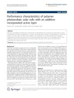
Figure 1.3 shows the typical structure of DSSCs. A typical DSSC device consists of
three components: dye-sensitized photoanode, electrolyte with redox couple and
counter electrode.
photoanode
Dye-sensitized photoanode: a mesoporous film of a wide band gap metal oxide is
coated on a transparent conducting glass (e.g. Fluorine doped tin oxide, FTO). The
6
semiconductor electrode is subsequently sensitized by dye solution. The photoanode
is the key element for light harvesting in DSSCs.
Figure 1.3 The typical structure of dye sensitized solar cells
a) Mesoporous material semiconductor film
The semiconductor film is made up of large band gap semiconductor, most commonly
TiO
2
. The mesoporous TiO
2
layer is multifunctional in DSSCs. It not only provides a
large surface area for dye adsorption, but also accepts photoelectrons produced by the
excited dye. Furthermore, it functions as conductor for photoelectron travelling to the
FTO electrode.
In general, the TiO
2
film is deposited via a TiO
2
paste on the FTO conducting glass.
The TiO
2
paste consists of 20 nm TiO
2
nanoparticles. To form the TiO
2
film, two
7
methods are commonly used: doctor-blading and screen-printing method. To reduce
effect of organic additives and increase interconnection network of TiO
2
nanoparticles,
annealing of the coated TiO
2
electrode is necessary.
Generally, increasing surface area of mesoporous TiO
2
film leads to enhanced dye
adsorption and better contact between dye and electrolyte. However, the
recombination process also increases with the increased surface area of TiO
2
film. To
solve this problem, some strategies have been studied to reduce recombination, such
as employing an organic spacer between TiO
2
and sensitizer.[20-23]
The typical used TiO
2
layer is a multiple layer, which is composed with a layer of
TiO
2
film with 20 nm TiO
2
particles and a layer of TiO
2
film 400 nm TiO
2
particles.[24, 25] The layer with 400 nm TiO
2
particle, used to enhance light
absorption is named scattering layer.
b) Dye
Generally, the dyes used in DSSCs are divided according to the structure: inorganic
complex dye and all organic dye. The most effective devices are fabricated by
ruthenium based inorganic dyes. However, since ruthenium is a rare metal, metal free
organic sensitizers with high extinction coefficient have been developed. A relatively
high efficiency of 9.8% has been obtained by metal free organic sensitizers.[19]
8
The properties of dye greatly affect the performance of DSSCs, since dye is the
essential element to harvest light and inject photoelectrons. The spectral overlapping
between the sensitizer and the AM 1.5G solar irradiance spectrum makes a large
contribution to the photocurrent and energy conversion efficiency of devices,
sensitizer with broad light absorption is expected, for instance, ruthenium dye C101
with light absorption almost throughout the visible light range showed an efficiency
over 11%.[26] To achieve more light absorption under low dye-loading conditions,
the molar extinction coefficient of the dye should be high enough. D149 is a typical
organic sensitizer with high extinction coefficient of 68,700 M
-1
cm
-1
at 526 nm.[27]
Electrolyte
Electrolyte consists of the redox couple for dye regeneration. The function of
electrolyte is to regenerate oxidized dye molecules. The most effective redox couple
is iodine/iodide.[17] In addition, SCN
-
/(SCN)
3
and SeCN
-
/(SeCN)
3
have been reported
as the redox couple with acceptable efficiencies.[28, 29]
Counter electrode
Since the counter electrode is used to reduce oxidized redox species and complete
external circuit of devices, high conductivity and stability are necessary for the
material of counter electrode. Normally, counter electrode is prepared by coating
catalytically active platinum particles on FTO glass.
9
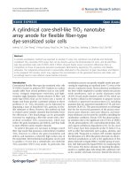
1.2.2 Working principle of DSSCs
The working principle of DSSCs under light radiation is shown in Figure 1.4. The
device generates photocurrent through a series of processes.
a) When the dye molecule is excited by sunlight irradiation, an electron is excited
from the HOMO level of the dye molecule to the LUMO level.
Figure 1.4 The working principle of dye sensitized solar cells
The excited photoelectron is injected to the mesoporous TiO
2
film. The injection
process from the excited ruthenium sensitizer is ultrafast, in the femtoseconds
range.[30-33]
b) The photoelectron injected travels through the mesoporous oxide film by diffusion
and is collected at the FTO glass and transferred to external circuit. Since the TiO
2
film is filled in electrolyte, a junction of large contact area is formed between the
TiO
2
particles and electrolyte. The photoelectrons diffuse by hopping.[34] The
10
charge transport time is typically about 0.1 - 10 milliseconds.
c) The oxidized dye molecule is regenerated by the redox couple normally I
-
in
electrolyte. This process is generally completed in microseconds. Since for DSSCs
with 20 years lifetime the turnover number is required to be 10
8
. The lifetime of
oxidized sensitizer should be larger than 100 s, while the regeneration time is 1
s.[34]
d) The electrons transferred from external circuit to the counter electrode are used to
regenerate oxidized redox species. To enhance the performance of devices, the
resistance of external electron transfer should be minimized. Research has shown
that the resistance can be reduced down to 1 cm
with platinum nanoparticles
clusters
As the photoelectrons in DSSCs are surrounded by dye and electrolyte, there are two
types of recombination processes that take place. The photoelectrons could recombine
with oxidized dye or electrolyte with electron acceptor (processes (e) and (f) in Figure
1.4). Recombination of the oxidized sensitizer, depending on the photoelectron
concentration in the TiO
2
film, ranges from s ~ ms scale. Recombination of
photoelectrons with the electrolyte is represented by the electron lifetime. The
competition between recombination processes and the generation of photocurrent
plays a key role in the energy conversion efficiency of DSSCs.