Analysis of dirichlet neumann and neumann dirichlet partitioned procedures in fluid structure interaction problems
Bạn đang xem bản rút gọn của tài liệu. Xem và tải ngay bản đầy đủ của tài liệu tại đây (1.09 MB, 89 trang )
ANALYSIS OF DIRICHLET-NEUMANN AND
NEUMANN-DIRICHLET PARTITIONED
PROCEDURES IN FLUID-STRUCTURE
INTERACTION PROBLEMS
XUE HANSONG
(B.Sc.(Hons.), NUS)
A THESIS SUBMITTED
FOR THE DEGREE OF MASTER OF SCIENCE
DEPARTMENT OF MATHEMATICS
NATIONAL UNIVERSITY OF SINGAPORE
2011
Acknowledgements
First of all, I would like to express my uttermost gratitude to my supervisor, Dr
Liu Jie, for offering me the opportunity to work under him, putting in great efforts and spending precious time to help, guide and encourage me, not only in this
entire research work, but also in non-academic related aspects. Within the past
two years he has broadened my view and knowledge in the area of computational
fluid dynamics and fluid-structure interaction. I have benefited greatly from his
enlightenment and inspiration in this area. Everything I have learned from him
is of endless benefit to my whole life. It has been really a great pleasure to work
under Dr Liu Jie and I really appreciate his patience.
I would like to thank especially Simon and Yvonne for their care and encouragement
from Karlsruhe, Germany during my graduate studies although we are so far apart.
I am very grateful to Dr and Mrs Ong for their support and good care during the
past twelve years in Singapore.
ii
Acknowledgements
iii
A thousand thanks to Cai Ruilun, Gaobing, Gaorui, Gongzheng, Jiang Kaifeng, Li
Xudong, Ma Jiajun, and Wangkang, for helping me in my graduate course studies.
I would like to thank my beloved parents in China and other who have helped me
in one way or the other.
Last but not least, to dedicate this work to my beloved wife, Zhihan, for her endless support, meticulous care and magnanimous understanding she has given to me.
Xue Hansong
October 2011
Contents
Acknowledgements
ii
Summary
vii
List of Figures
ix
1 Introduction
1
1.1
An overview . . . . . . . . . . . . . . . . . . . . . . . . . . . . . . .
1
1.2
The organization of the thesis . . . . . . . . . . . . . . . . . . . . .
5
2 Problem Setting
7
2.1
Structure domain . . . . . . . . . . . . . . . . . . . . . . . . . . . .
8
2.2
Fluid domain . . . . . . . . . . . . . . . . . . . . . . . . . . . . . .
9
2.3
The Arbitrary Lagrangian Eulerian(ALE) formulation of the Navier-
2.4
Stokes equation . . . . . . . . . . . . . . . . . . . . . . . . . . . . .
10
Coupling conditions . . . . . . . . . . . . . . . . . . . . . . . . . . .
14
iv
Contents
v
3 Time discrete system and domain decomposition method
3.1
3.2
Full FSI problem and time discrete system . . . . . . . . . . . . . .
15
3.1.1
Semi-implicit scheme . . . . . . . . . . . . . . . . . . . . . .
17
3.1.2
Implicit scheme . . . . . . . . . . . . . . . . . . . . . . . . .
18
Domain decomposition method . . . . . . . . . . . . . . . . . . . .
19
4 Convergence analysis of simplified problems
4.1
4.2
4.3
15
23
Heat-wave(HW) 1D model . . . . . . . . . . . . . . . . . . . . . . .
23
4.1.1
ND partitioned procedure . . . . . . . . . . . . . . . . . . .
24
4.1.2
DN partitioned procedure . . . . . . . . . . . . . . . . . . .
27
Stokes-algebraic generalized string(SAGS) 1D model . . . . . . . . .
27
4.2.1
The structural problem . . . . . . . . . . . . . . . . . . . . .
28
4.2.2
The fluid problem . . . . . . . . . . . . . . . . . . . . . . . .
29
4.2.3
Fluid-structure interaction . . . . . . . . . . . . . . . . . . .
29
4.2.4
ND partitioned procedure . . . . . . . . . . . . . . . . . . .
30
4.2.5
DN partitioned procedure . . . . . . . . . . . . . . . . . . .
36
Stokes-linear elasticity(SLE) 2D model . . . . . . . . . . . . . . . .
37
4.3.1
ND partitioned procedure . . . . . . . . . . . . . . . . . . .
39
4.3.2
DN partitioned procedure . . . . . . . . . . . . . . . . . . .
45
5 Geometric convergence of domain decomposition method
47
5.1
Geometric convergence for ND partitioned procedure . . . . . . . .
49
5.2
Geometric convergence for DN partitioned procedure . . . . . . . .
58
5.3
Parameter estimation and improved convergence rate for the case of
heat-wave equations coupling . . . . . . . . . . . . . . . . . . . . .
61
vi
Contents
6 Conclusion
68
Bibliography
71
Summary
In recent decades, the development and application of respective modeling and
simulation approaches for fluid-structure interaction (FSI) problems have grasped
much attention. While solving FSI problems, partitioned scheme shows its efficiency by using a modular algorithm in which the equations of fluid and structure
are solved separately in an iterative manner through the exchange of suitable transmission conditions at the FS interface.
The goal of this work is to verify in terms of the convergence behavior that using
structure normal stress as the boundary condition along the FS interface in the fluid
solver and hence prescribing displacement boundary condition for the structure
is actually better than the opposite approach. In fact, the opposite approach
has great numerical instabilities, especially when the iteration time step is small,
but our proposed approach can reduced this instabilities and hence has a better
convergence behavior.
Based on three different simplified models of the fluid and the structure, i.e. Heatwave 1D model, Stokes-algebraic generalized string 1D mode and Stokes-linear
vii
viii
Summary
elasticity 2D model, we present a detailed analysis of the convergence behavior
to substantiate our claim by deriving a reduction factor at each iteration of the
partitioned algorithm. In particular, these model problems are used to highlighted
some aspects that probably will arise in the context of applying partitioned scheme
to FSI problems.
Furthermore, if we ignore the fluid domain deformation and also the convection
term in fluid equation, we can prove the geometric convergence of the iteration that
enforces the continuities of velocities and normal stresses along the FS interface.
An example of heat-wave equations coupling is also given to show an improved
convergence rate and estimate the parameters in its geometric convergence.
List of Figures
2.1
Example of the computational fluid domain Ωft
. . . . . . . . . . .
7
2.2
Example of the computational solid domain Ωst . . . . . . . . . . . .
8
2.3
A longitudinal section of the fluid domain Ωft
2.4
Comparison between the Lagrangian and the ALE approach. The
. . . . . . . . . . . .
11
reference computational domain Ωf0 is mapped by (a) the Lagrangian
4.1
mapping Lt and by (b) the ALE mapping At . . . . . . . . . . . . .
12
Schematic representation of the computational domain . . . . . . .
28
ix
Chapter
1
Introduction
1.1
An overview
Fluid-structure interaction (FSI) is the interaction of some movable or deformable
structure with an internal or surrounding fluid flow. It can also be considered as
a coupled problem, consisting of two or more domains which interact at common
boundaries. This kind of mutual influence of a flexible structure with a flowing
fluid in which it is submersed or by which it is surrounded gives rise to a rich variety
of frequently occurring physical phenomenon with applications in many fields of
engineering as well as in applied sciences. Furthermore, it is a crucial consideration
in the design of many engineering systems[33]. In recent years, it has received much
attention and has become one of the major research activities due to its growing
importance. Some of the examples are: aeroelasticity[14, 44, 29]; helicopters[37,
24]; the vibration of turbine and compressor blades; the sloshing in tanks[34];
the response of bridges and skyscrapers to winds; membranous structures[51]; the
description of the mechanical behavior of cells[13] or, more generally, the organic
fluid mechanics; acoustic problems; hemodynamics[43, 6, 22].
1
2
Chapter 1. Introduction
FSI can be either oscillatory or non-oscillatory. In the oscillatory interaction,
the strain induced in the sold structure causes it to move in such a way that
the source of strain is reduced, and then the solid structure returns to its former
position to repeat the process, while the non-oscillatory interaction simply means
the interaction is not repeatable. Failing to consider the effects of FSI oscillatory
can be sometimes very catastrophic, especially when the solid structure consists
of materials which are susceptible to fatigue. One of the most infamous examples
of large-scale failure is the Tacoma Narrows Bridge in 1940. Aircraft wings and
turbine blades can also break down due to FSI. We also know FSI is a necessary
component for the analysis of aneurysms in large arteries and artificial heart valves.
FSI problems in general are too complex to solve analytically. Therefore, in order
to understand these phenomenons, we need numerical simulation to model the
behavior of FSI. With a numerical simulation, the real behavior of a flow or a solid
can be depicted. The development and application of respective modeling and
simulation approaches for FSI have gained great attention over the past decades,
yet it is still challenging.
Two main approaches that exist for the simulation of FSI problems are the monolithic approach[25, 26, 28, 7], or sometimes referred as the direct method[45], and
the partitioned approach[15, 47, 41, 39, 16, 38, 40, 32], also known as the iterative method[45, 46, 5]. For the monolithic approach, the equations governing the
fluid flow and the displacement of the structure are solved simultaneously with
a single solver. While the partitioned approach is based on the coupling of one
module for solving the fluid equations and another one for solving the structural
displacement[50, 49, 52]. The monolithic approach requires a code developed for
this particular combination of FSI problems whereas the partitioned approach preserves the software modularity since the latest developed solvers for either fluid
or structure can be easily incorporated and this offers significant benefits in terms
1.1 An overview
of efficiency. Besides this advantage, the partitioned approach can also facilitate
the solution for the fluid and structure equations with various, efficient techniques
which have been developed in past decades specifically designed for either fluid
equations or structure equations. On the other hand, a significant requirement
in partitioned approach is the development of stable and accurate coupling algorithm. Commonly used numerical methods for FSI calculation are finite element
method and finite volume method which are based on the solution of partial differential equations. The area is calculated by using a computational grid, which is
divided into individual cells, where the differential equations are solved by taking
into account of appropriate boundary conditions. This results in a large system of
equations to be solved directly or iteratively.
Another point of view for partitioned approach is the coupling strength. The
coupling of the fluid and the structure comes from the continuities of velocities
and normal stresses along the FS interface. According to this we can classify the
coupling into three different categories[31, 15, 41, 47, 17], i.e.
• implicit partitioned approach(strong coupling): in every time step, the algorithm couples the fluid and structure equations repeatedly until the continuities of velocities and normal stresses along the FS interface are enforced.
• semi-implicit partitioned approach: in every time step, the algorithm couples
reduced fluid equations and structure equations repeatedly until the continuities of velocities and normal stresses along the FS interface are enforced.
• explicit partitioned approach(weak coupling): perform the coupling of fluid
and structure equations only once in each time step.
The continuities of velocities along the FS interface can be considered as a Dirichlet type boundary condition, while the continuities of normal stresses along the
3
4
Chapter 1. Introduction
FS interface can be considered as a Neumann type boundary condition. When
the fluid problem is iteratively solved with the structure velocity as a Dirichlet
boundary condition and the structure problem is solved with the fluid normal
stress as a Neumann boundary condition, we call it Dirichlet-Neumann(DN) partitioned procedure. In this case two sub-problems need to be solved: one for fluid
and the other for structure. On the other hand when the fluid problem is solved
with structure normal stress as a Neumann boundary condition and the structure
problem is solved with displacement as a Dirichlet boundary condition, we call it
Neumann-Dirichlet(ND) partitioned procedure.
As shown in [10, 21], the stability of partitioned approach is dictated by the amount
of added-mass effect. In other words, when the fluid and solid densities are close to
each other or the domain is slender, a strong added-mass effect in the system will
occur and hence, it gives rise to unconditional numerical instability regardless of
the discretization parameters. Thus, it often requires a large relaxation to converge
and a quite high number of iterations. A number of strategies have been proposed
in the literature in order to overcome some of these infamous numerical instabilities:
for implicit approach, please refer to [20], semi-implicit approach[3, 17, 18, 42, 48]
and explicit approach[8, 9, 23, 36].
However, we feel that at least part of this instability is a consequence of the choice
of interface conditions assigned to sub-problems. Conventionally, only DN partitioned procedure is considered, but if we use Neumann boundary condition for the
fluid sub-problem and Dirichlet boundary condition for the structure(ND partitioned procedure), We feel that this instability can be greatly reduced than using
the opposite approach. Although in [3, 2] it is claimed that the ND partitioned
procedure has even worse convergence properties than the DN one, no substantial
evidence was given.
1.2 The organization of the thesis
Therefore, in this thesis we focus on the implicit partitioned approach, which is
based on subsequent solutions of fluid and structure sub-problems and every subproblem is solved separately. Our aim is to show that the ND partitioned procedure
is a better strategy that the DN partitioned procedure.
1.2
The organization of the thesis
The outline of the thesis is as follows:
In Chapter 2, we first introduce linear elastodynamics equation for the structure
domain and incompressible Navier-Stokes equation for the fluid domain. Since the
Navier-Stokes equation is only counted for fixed domain and in real coupled FSI
problems the boundary most likely moves, so we present the arbitrary Lagrangian
Eulerian formulation of Navier-Stokes equation as it can take into account of the
moving boundaries. We also give two coupling conditions which are in need to be
enforced at the FS interface, i.e. the continuities of velocities and normal stresses.
In Chapter 3, after presenting the full FSI problem, with the time discretization we
describe the semi-implicit procedure and the implicit procedure. Next, we illustrate
the ND and DN partitioned procedure as a domain decomposition method which
is usually adopted to solve FSI problems.
In Chapter 4, we use three reduced models with suitable simplifying assumptions
to support our claim that the ND partitioned procedure is actually better than
the DN partitioned procedure. The first one is a 1D model, which consists of
heat and wave equation. The next one is a Stokes-algebraic generalized string 1D
model where the unsteady Stokes equation is used for fluid domain and a string
model for membrane is used for the structure domain. In these two 1D models,
5
6
Chapter 1. Introduction
the FS interface moves only along the normal direction. The last one is a Stokeslinear elasticity 2D model, where the FS interface moves along both normal and
tangential directions and the fluid part is still the Stokes equation, but the structure
part comes from elastodynamics equation. In all the cases we define a reduction
factor as a measurement for the convergence and show that this reduction factor
for the ND partitioned procedure has an order which is smaller the the opposite
approach.
In Chapter 5, we show the geometric convergence of the general ND and DN
partitioned procedure with the assumption that the fluid domain deformation and
convection in fluid equations are ignored. After that we use a heat-wave equations
coupling to show an improved convergence rate and aslo parameters in its geometric
convergence can be estimated.
Finally in Chapter 6, some conclusions based on this work are drawn and possible
future works are discussed.
Chapter
2
Problem Setting
In this chapter, we present the governing equations of FSI problem, which consists
of the structure domain, the fluid domain and the coupling conditions along the
interface.
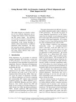
Figure 2.1: Example of the computational fluid domain Ωft
At first, we consider a computational domain Ωt ∈ Rn where t represents the time
and n = 2 or 3. This domain is split into two subdomains Ωft and Ωst respectively.
Ωft is occupied by the fluid and Ωst the structure. The FS interface Σt is the common
7
8
Chapter 2. Problem Setting
Figure 2.2: Example of the computational solid domain Ωst
boundary shared by Ωft and Ωst (see Figure 2.1), i.e. Σt = ∂Ωft ∩ ∂Ωst , while Γf,1
t ,
s,1
Γf,2
and Γs,2
are the artificial sections of fluid and structure. Furthermore,
t , Γt
t
nf is the outward normal on ∂Ωft and ns is the outward normal on ∂Ωst . We know
on Σt , nf = −ns and the initial configuration Ω0 at t = 0 is considered as the
reference one.
2.1
Structure domain
A purely Lagrangian approach is used to describe the structure kinetics. We denote
the reference configuration by Ωs := Ωs0 . The structure is assumed to be a linear
elastic material and is governed by the elastodynamics equation
ρs ∂tt η = ∇ · σ s + g
in Ωs × (0, T )
(2.1)
where η is the structure displacement, ρs is the density of the structure and g is
the external body force acting on the structure. We use linear constitutive law
2.2 Fluid domain
9
which relates η and the Cauchy stress tensor σ s
σ s (η) = µs (∇η + ∇η ) + λs (∇ · η)I
where ∇ denotes the spatial gradient operator,
µs =
Eυ
E
and λs =
2(1 + υ)
(1 + υ)(1 − 2υ)
are the Lam´e constants, E is the Young modulus, υ is the Poisson modulus, and
I is the identity tensor. In the case when the structure is incompressible, we have
υ = 0.5. Then the Cauchy stress tensor is given by
σ s (η, q) = µs (∇η + ∇η ) − qI
where q is the structure pressure and the governing equation (2.1) becomes
2.2
ρs ∂tt η = ∇ · σ s + g
in Ωs × (0, T ),
(2.2)
∇·η =0
in Ωs × (0, T ).
(2.3)
Fluid domain
The fluid is normally described by the Eulerian formulation and is assumed to
be homogeneous, Newtonian and incompressible. It is governed by incompressible
Navier-Stokes equation
ρf (∂t u + u · ∇u) = ∇ · σ f + f
∇·u=0
in Ωft × (0, T ),
(2.4)
in Ωft × (0, T )
(2.5)
where ρf is the density of the fluid, u is the velocity, f is the external body force
acting on the fluid and σ f is the Cauchy stress tensor of the fluid given by
σ f (u, p) = ρf ν f (∇u + ∇u ) − pI
10
Chapter 2. Problem Setting
in which ν f is the kinematic viscosity, p is the pressure and I is the identity tensor.
Ωft is the fluid domain at time t. Equation (2.4) is nonlinear, couples the velocity
and the pressure fields and is derived from the Newton’s Second Law which states
that the momentum is always conserved. Its detailed derivation can be found in
[1, 43]. Equation (2.5) comes from the continuity equation, which is arising from
the conservation of mass, i.e.
∂ρf
+ ∇ · (ρf u) = 0.
∂t
(2.6)
Since the fluid is incompressible and the value of ρf is constant, this gives equation
(2.5).
2.3
The Arbitrary Lagrangian Eulerian(ALE) formulation of the Navier-Stokes equation
In previous section we have introduced the Navier-Stokes equation in a fixed domain, according to the Eulerian approach where the independent spatial variable
are the coordinates of a fixed Eulerian system. However, in real coupled FSI problem, an essential feature of the problem under consideration is the motion of the
boundary of the fluid domain. The geometry of the fluid domain may change substantially with respect to time. This is obvious especially in the case when blood
flows in large arteries where the forces exerted by the flowing blood stream will
cause the vessel wall to vary significantly.
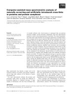
We consider a longitudinal section of the fluid domain in Figure 2.3 with the
assumption that the fluid flows into Γf,1
and comes out from Γf,2
t
t . The position of
Γf,1
and Γf,2
may vary with time due to the displacement of Σ1t and Σ2t . However,
t
t
Γf,1
and Γf,2
are artificial sections and their positions should remain fixed. Clearly
t
t
in this case the Eulerian approach becomes impractical.
2.3 The Arbitrary Lagrangian Eulerian(ALE) formulation of the
Navier-Stokes equation
11
Figure 2.3: A longitudinal section of the fluid domain Ωft
A possible alternative would be to use the Lagrangian approach. As we mentioned
earlier, Ω0 is the reference configuration and now we denote ΩLt to be the corresponding domain in the current configuration by the Lagrangian mapping Lt ,
i.e.
ΩLt = Lt (Ω0 ) ∀t ∈ (0, T ).
(2.7)
Since the fluid velocity at the boundary Σ1t and Σ2t is equal to the boundary velocity,
the Lagrangian mapping effectively maps Σ10 and Σ20 in the reference configuration
to the correct boundary position Σ1Lt and Σ2Lt at each time t. However, the artificial
f,2
boundaries Γf,1
0 and Γ0 in the reference configuration will be transported along the
f,2
fluid trajectories, into Γf,1
Lt and ΓLt (see Figure 2.4). This is clearly not acceptable,
particularly if one wants to study the problem for a relatively large period of time.
Indeed, the domain rapidly becomes highly distorted.
Therefore, we want to keep the boundaries Γf,1
and Γf,2
fixed when there is a
t
t
displacement of Σ1t and Σ2t . It is convenient to formulate the problem in the
Arbitrary Lagrangian Eulerian(ALE)[12, 27] description, which relies on a moving
12
Chapter 2. Problem Setting
Figure 2.4: Comparison between the Lagrangian and the ALE approach. The
reference computational domain Ωf0 is mapped by (a) the Lagrangian mapping Lt
and by (b) the ALE mapping At
reference frame. It accounts for the temporal deformation of the fluid domain Ωft .
The ALE mapping can be considered as an appropriate lifting of the structure
displacement and is defined as
At : Ωf0 → ΩfAt ,
X → x(t, X) = At (X)
(2.8)
which provides the spatial coordinates (t, x) in terms of the ALE coordinates (t, X),
with the basic requirements that At retrieves at each time t, the desired computational domain, i.e.
Ωft := ΩfAt = At (Ωf0 ) ∀t ∈ (0, T ).
2.3 The Arbitrary Lagrangian Eulerian(ALE) formulation of the
Navier-Stokes equation
13
With this we could define the domain velocity field as
w(t, X) =
∂
x(t, X)
∂t
(2.9)
whose the Eulerian coordinates is expressed as
w(t, X) = w(t, A−1
t (x)) = w(t, x).
(2.10)
Conventionally we indicate u to be the composition of u with the ALE mapping,
i.e. u = u ◦ At . The ALE trajectory TX for all X ∈ Ω0 is defined as
TX = {(t, x(t, X)) , t ∈ (0, T )},
(2.11)
and the ALE derivative of u as the time derivative along a trajectory TX is
DA
u
Dt
: (0, T ) × Ωt → R3 ,
DA
u(t, x)
Dt
=
∂
u(t, X),
∂t
(2.12)
X = A−1
t (x).
By applying the chain rule of derivation of composed function, we have
∂
∂
∂u ∂x
∂u
u(t, X) = u(t, x(t, X)) =
+
· ∇u =
+ w · ∇u
∂t
∂t
∂t
∂t
∂t
(2.13)
where now the gradient is expressed in terms of the x coordinates. Therefore, we
obtain the ALE time derivative of the velocity u, i.e.
∂u
DA u
=
+ w · ∇u
Dt
∂t
where
∂u
∂t
(2.14)
is the Eulerian derivative and w is the velocity of the points of the fluid
domain defined by the ALE map in equation (2.10). We substitute equation (2.14)
into equation (2.4) to obtain the ALE formulation of the Navier-Stokes equation,
i.e.
ρf
DA u
+ ρf (u − w) · ∇u = ∇ · σ f + f in Ωft × (0, T ),
Dt
∇ · u = 0 in Ωft × (0, T )
(2.15)
(2.16)
14
Chapter 2. Problem Setting
2.4
Coupling conditions
Two coupling conditions are enforced at the interface: the continuity of fluid and
structure velocities, i.e.
u = ∂t η
on Σt × (0, T )
(2.17)
due to the adherence condition. The other one is the continuity of normal stresses,
i.e.
σ s · ns + σ f · nf = 0
which expresses the action-reaction principle.
on Σt × (0, T )
(2.18)
Chapter
3
Time discrete system and domain
decomposition method
In this chapter, we give the time discretized version of our FSI problem: one is
semi-implicit procedure and the other is implicit procedure. From the implicit procedure we outline the algorithm for ND partitioned procedure and DN partitioned
procedure respectively.
3.1
Full FSI problem and time discrete system
By combining the governing equations for fluid and incompressible structure, and
their coupling conditions at the interface, we have the full FSI problem in the
strong form, i.e.
1. Fluid structure problem: find the fluid velocity u, the pressure p, and the
15
16
Chapter 3. Time discrete system and domain decomposition method
structure displacement η such that
ρs ∂tt η = ∇ · σ s + g
∇·η =0
ρf DA u + ρf (u − w) · ∇u = ∇ · σ f + f
Dt
∇·u=0
u = ∂t η
σ s · ns + σ f · nf = 0
in Ωs × (0, T ),
in Ωs × (0, T ),
in Ωft × (0, T ),
in Ωft × (0, T ),
(3.1)
on Σt × (0, T ),
on Σt × (0, T ),
with suitable boundary conditions on the artificial sections and initial condition in Ω0 .
2. Geometry problem: given the interface structure displacement η|Σt , find a
map At : Ωf0 → ΩfAt , e.g., through a harmonic extension Ext[2] of the boundary displacement
At (x0 ) = x0 + Ext(η|Σ0 )
such that Ωft = At (Ωf0 ).
A detailed description of this harmonic extension is in[2]. The position of the
FS interface is an unknown of the coupled problem. It introduces a geometrical
nonlinearity. The convective term of the fluid problem is nonlinear and, in case of
using an ALE formulation, also depends on the velocity of the fluid domain.
As we can see here, FSI problem is a system of highly nonlinear partial differential
equations. This kind of nonlinearity can be treated numerically in several ways,
either explicitly, where extrapolation from previous time step is adopted, or implicitly, where at each time step the FSI problem is solved by Picard, Newton,
or quasi-Newton iterations[19, 35].Whatever strategies are adopted, a sequence of
linearized FSI problems, which are coupled through the continuities of velocities
and normal stresses on the FS interface, has to be solved.