Development of oil loaded alginate composite microspheres by spray drying
Bạn đang xem bản rút gọn của tài liệu. Xem và tải ngay bản đầy đủ của tài liệu tại đây (5.09 MB, 198 trang )
DEVELOPMENT OF OIL-LOADED ALGINATE-COMPOSITE
MICROSPHERES BY SPRAY DRYING
TAN LAY HUI
(B. Sc. (Pharm.) (Hons.), NUS)
A THESIS SUBMITTED
FOR THE DEGREE OF DOCTOR OF PHILOSOPHY
DEPARTMENT OF PHARMACY
NATIONAL UNIVERSITY OF SINGAPORE
2008
i
ACKNOWLEDGEMENTS
I wish to express my heartfelt gratitude to my supervisors, A/P Paul Heng Wan
Sia and A/P Chan Lai Wah for their guidance and support for both my research
and personal life. I am also grateful for their effort put into reading and giving
comments and suggestions for improvements on my manuscripts. I also sincerely
thank them for giving me the opportunity to discover and explore the various
aspects of research work. I also deeply appreciate the moral support given to me
when I took time off research to start my family.
I also wish to thank the Head of the Department of Pharmacy, A/P Chan Sui Yung,
for the support she has given me throughout my years as a graduate student. I also
thank her for the use of the departmental facilities for my research project. I would
also like to acknowledge the research scholarship awarded by the National
University of Singapore.
Many thanks also to my fellow laboratory mates, especially Wai See, Sze Nam,
Huey Ying, Kang Teng, Ai Ling, Josephine and Qiyun for guiding and helping me
in my research and for being good role models for me to emulate. I also thank
Teresa, Mei Yin and Peter for the technical assistance provided for my research
work. My sincere appreciation also goes to Dr Anton Dolzhenko for his assistance
in performing the NMR studies.
I would also like to express my heartfelt thanks to my mother, sister and auntie for
their unfailing support and faith in me. Without their moral and financial support,
I would not have been able to embark on and complete my undergraduate and
ii
graduate studies. I also wish to thank my husband for his love and encouragement
through these years and my children, Amanda, Bethany and Christian, for
enriching my life in a way that no others could.
Last but not least, I would like to dedicate this work to my late father, for without
him, I would not be what I am today.
Thank you.
Lay Hui
July 2008
iii
CONTENTS
ACKNOWLEDGEMENTS
ii
CONTENTS
iv
SUMMARY
ix
LIST OF TABLES
xi
LIST OF FIGURES
xii
I. INTRODUCTION
1
A. Microencapsulation
1
A1. Significance of microencapsulation
1
A2. Microencapsulation of oils
2
A3. Fish oils and polyunsaturated fatty acids (PUFAs)
3
A3.1 Microencapsulation of fish oils
6
A4. Methods of oil encapsulation
7
A4.1 Chemical processes
7
A4.1.1 Complex coacervation
7
A4.1.2 Other processes
8
A4.2 Physical processes
A4.2.1 Spray drying
A5. Wall materials for oil encapsulation by spray drying
9
9
11
A5.1 Starches and sugars
12
A5.2 Gums
13
A5.3 Proteins
14
A5.4 Alginates
15
B. Evaluation of oil-loaded microspheres
B1. Mechanical strength
18
19
iv
B1.1 Single-microparticle studies
19
B1.2 Bulk-microparticle studies
22
C. Process analytical technology (PAT)
23
C1. Definition of PAT
23
C2. PAT tools
24
C3. PAT in particle sizing
25
C3.1 Focused beam reflectance measurement
(FBRM)
25
C3.2 Laser diffraction
27
C3.3 Imaging methods
28
C3.4 Other methods
29
C4. PAT for microsphere sizing during spray drying
29
II. HYPOTHESES AND OBJECTIVES
31
III. EXPERIMENTAL
32
A. Materials
32
A1. Alginates
32
A2. Starch
32
A3. Fish oil
33
A4. Maltodextrin
33
A5. Materials used in microsphere characterization
33
A5.1 Stainless steel shots
33
A5.2 Ferronyl powder
33
B. Methods
34
B1. Viscosity reduction of alginate solutions
34
B2. Viscometry of alginate solutions
34
v
B3. Nuclear magnetic resonance (NMR) studies
34
B4. Emulsion preparation
35
B5. Emulsion oil droplet size analysis
36
B6. Spray drying of emulsions
37
B7. Yield
37
B8. Size determination
38
B8.1 Light microscopy
38
B8.2 In-line and at-line laser diffraction
38
B8.3 Off-line laser diffraction
40
B9. Microsphere morphology
41
B9.1 Scanning electron microscopy (SEM) studies
41
B9.2 Microsphere roundness
41
B10. Microsphere true density determination
42
B11. Flow determination
42
B11.1 Poured bulk density
43
B11.2 Tapped bulk density
43
B11.3 Carr’s index
44
B12. Determination of microsphere surface area
44
B12.1 BET specific surface area
44
B12.2 Theoretical specific surface area
45
B13. Determination of microencapsulation efficiency
(ME)
46
B13.1 Surface oil
46
B13.2 Total oil content, microencapsulated oil and
ME
47
B14. Determination of oil content and stability on storage
48
vi
B14.1 Sample preparation
48
B14.2 Gas chromatography
48
B14.3 Calculation of EPA and DHA content
49
B14.4 Degradation kinetics
50
B15. Microsphere mechanical strength
51
B15.1 Microsphere compression
51
B15.2 Determination of oil leakage after
compression
51
B16. Statistical analysis
IV. RESULTS AND DISCUSSION
A. Formulation and production of microspheres
A1. Emulsion formulation
A1.1 Pre-treatment of alginate solutions
A1.1.1 Autoclaving of alginate solutions
A1.2 Emulsion stability
A1.2.1 Effect of homogenization
conditions
A2. Optimization of spray drying conditions
52
53
53
53
53
55
58
58
64
B. Microsphere characterization
69
B1. Physical properties
69
B1.1 Microencapsulation efficiency (ME)
69
B1.2 Microsphere morphology
71
B1.3 Microsphere size
77
B1.4 Microsphere roundness
80
B1.5 Specific surface area
82
B1.6 Microsphere true density
86
vii
B1.7 Bulk and flow properties
88
B1.8 Yield
90
B1.9 Summary
92
B2. Oil content and stability on storage
93
B3. Mechanical properties
107
B3.1 Method development
108
B3.2 Oil leakage studies
111
C. PAT for microsphere sizing
113
C1. In-line monitoring of real-time changes
114
C2. Microsphere sizing
118
C2.1 In-line laser diffraction
120
C2.2 At-line laser diffraction
129
C2.2.1 Optimization of sizing conditions
129
C2.2.2 Microsphere sizing
133
C2.3 Off-line laser diffraction
136
C2.4 Light microscopy
136
C3. Summary
139
V. CONCLUSION
140
VI. REFERENCES
142
VII. APPENDIX
177
VIII. PUBLICATIONS / PRESENTATIONS ARISING FROM THIS
STUDY
183
viii
SUMMARY
Microencapsulation is a method that is commonly used in the food and
pharmaceutical industries for various purposes that include controlled release and
protection of sensitive materials from degradation. It has been found to be a useful
way to retard the oxidation process and improve the handling properties of ω-3
polyunsaturated fatty acids present in fish oils. Various wall materials and
methods have been used for the microencapsulation of fish oils. Although
alginates have wide pharmaceutical applications as excipients and formulation
aids in many drug delivery systems, little information is available on its use as a
wall material for oil encapsulation, especially by spray drying. This provides the
impetus for the present study. Microencapsulated products generally need to be
intact to carry out their functions. However, the mechanical properties of oilloaded microspheres are not well characterized. This warrants further
investigations to be conducted.
Process analytical technology (PAT) has been applied to pharmaceutical processes
for the purposes of quality improvement and improved process understanding.
The particle size distribution of a pharmaceutical product is an important quality
characteristic, and PAT has been applied to milling and crystallization processes
for real-time monitoring of particle size. However, little scientific literature is
available on its application to particle sizing during spray drying. It was therefore
of interest to explore the feasibility of applying an in-process particle sizer as a
PAT tool to the spray drying operation during microsphere production.
ix
Fish oil-containing emulsions consisting of blends of alginate and modified starch
as wall material were spray dried at conditions optimized to produce microspheres
with the highest microencapsulation efficiencies and yield. The properties of the
microspheres, such as size and morphology, true density, flow and specific surface
area, were evaluated. In addition, storage stability studies were carried out to
assess the protective capability of the microsphere matrices composed of different
alginate type and content. The mechanical properties of the microspheres were
further investigated through compression studies.
Partial substitution of modified starch with alginate produced microspheres which
generally performed better in terms of oil holding and oxidative protective
capabilities. This could be due to the formation of larger and microspheres with
the incorporation of alginate into the microsphere wall matrix. It also resulted in a
product with better flow and yield. However, between the 2 grades of alginate
studied, Manucol LB appeared to perform better in these aspects. The addition of
alginate also made the microspheres more resistant to compression. Application of
an in-process particle size analyzer during the spray drying process allowed the
elucidation of real-time information regarding microsphere size changes
especially during process start-up and shut-down.
For highly agglomerated
products like the microspheres produced in the present study, an at-line set-up was
found to be more useful for the determination of individual microsphere size.
x
LIST OF TABLES
Table 1
Properties of alginates used.
32
Table 2
Composition of wall materials used.
36
Table 3
Compositional data of alginates before and after autoclaving.
58
Table 4
Stability of emulsions produced from different formulations
with 250 % oil loading.
60
Table 5
(A) Mean oil droplet size and (B) size change on standing
for emulsions produced at different homogenization
conditions.
61
Table 6
Mean oil droplet size for all emulsion formulations prepared.
63
Table 7
(A) Design matrix and (B) analysis of effects for
microspheres made using formulation C.
66
Table 8
(A) Design matrix and (B) analysis of effects for
microspheres made using formulation LB10.
67
Table 9
(A) Design matrix and (B) analysis of effects for
microspheres made using formulation LBB10.
68
Table 10
(A) Theoretical specific surface area and (B) index of
indentation of microspheres produced using different
formulations.
85
Table 11
Carr’s indices for bulk microspheres.
89
Table 12
The relationship between particle size and flow properties
(adapted from Staniforth, 2002).
89
Table 13
Parameters derived from the Weibull model for EPA and
DHA degradation at (A) 50 %, (B) 100 % and (C) 150 % oil
loading.
104
Table 14
Factors affecting extent of oil leakage from compressed
microspheres.
109
Table 15
Dv(50) and Span values measured using in-line laser
diffraction (ILLD), at-line laser diffraction (ALLD), off-line
laser diffraction (OLLD) and light microscopy (LM) for
microspheres produced using formulations (A) C and
(B) LB10.
119
xi
LIST OF FIGURES
Figure 1
Diagrammatic representation of different microparticle
morphologies: (a) matrix type; (b) reservoir type;
(c) polynuclear type; (d) microencapsulated microcapsules
(adapted from Arshady, 1993).
2
Figure 2
Structures
of
(a)
eicosapentaenoic
(b) docosahexaenoic acid.
and
4
Figure 3
Structure of alginate showing the (a) mannuronate residue,
(b) guluronate residue, (c) mannuronate block conformation,
(d) guluronate block conformation and (e) heteropolymeric
block conformation (adapted from Gacesa, 1988 and
Tønnesen and Karlsen, 2002).
17
Figure 4
Diagrammatic representation of a micromanipulator set-up
(adapted from Zhang et al., 1999).
21
Figure 5
Diagrammatic representation of an FBRM probe (adapted
from Kail et al., 2008).
26
Figure 6
Diagrammatic representation of a typical laser diffraction
instrument (adapted from Black et al., 1996).
28
Figure 7
Layout of the spray dryer with the in-line and at-line laser
diffraction set-up (not drawn to scale).
40
Figure 8
Effect of autoclaving duration on flow times of 1 % w/v (○),
5 % w/v (□), 10 % w/v (∆) Manucol LB and 1 % w/v (●),
5 % w/v (■), 10 % w/v (▲) Manugel LBB solutions (dotted
line represents flow time of a 15 % w/v solution of modified
starch).
57
Figure 9
Effects of alginate addition and oil loading on
microencapsulation efficiency of C (◊), LB1 (○), LB5 (□),
LB10 (∆), LBB1 (●), LBB5 (■) and LBB10 (▲)
microspheres.
70
Figure 10
SEM photomicrographs of (a) C, (b) LB1, (c) LB5,
(d) LB10, (e) LBB1, (f) LBB5 and (g) LBB10 microspheres
produced with 50 % oil loading.
72
Figure 11
SEM photomicrographs of (a) C, (b) LB1, (c) LB5,
(d) LB10, (e) LBB1, (f) LBB5 and (g) LBB10 microspheres
produced with 150 % oil loading.
73
Figure 12
Mechanism of formation for skin-forming particles (adapted
from Walton, 2000).
76
acid
xii
Figure 13
Effects of alginate addition and oil loading on mean size of
C (◊), LB1 (○), LB5 (□), LB10 (∆), LBB1 (●), LBB5 (■)
and LBB10 (▲) microspheres.
78
Figure 14
Effects of alginate addition and oil loading on roundness
values of C (◊), LB1 (○), LB5 (□), LB10 (∆), LBB1 (●),
LBB5 (■) and LBB10 (▲) microspheres.
81
Figure 15
Effects of alginate addition and oil loading on BET specific
surface area of C (◊), LB1 (○), LB5 (□), LB10 (∆),
LBB1 (●), LBB5 (■) and LBB10 (▲) microspheres.
83
Figure 16
Effects of alginate addition and oil loading on true density of
C (◊), LB1 (○), LB5 (□), LB10 (∆), LBB1 (●), LBB5 (■)
and LBB10 (▲) microspheres.
87
Figure 17
Effects of alginate addition and oil loading on yield of C (◊),
LB1 (○), LB5 (□), LB10 (∆), LBB1 (●), LBB5 (■) and
LBB10 (▲) microspheres.
91
Figure 18
EPA and DHA content on storage for unencapsulated oil (♦),
C (◊), LB1 (○), LB5 (□), LB10 (∆), LBB1 (●), LBB5 (■)
and LBB10 (▲) microspheres produced with 50 % oil
loading.
95
Figure 19
EPA and DHA content on storage for unencapsulated oil (♦),
C (◊), LB1 (○), LB5 (□), LB10 (∆), LBB1 (●), LBB5 (■)
and LBB10 (▲) microspheres produced with 100 % oil
loading.
96
Figure 20
EPA and DHA content on storage for unencapsulated oil (♦),
C (◊), LB1 (○), LB5 (□), LB10 (∆), LBB1 (●), LBB5 (■)
and LBB10 (▲) microspheres produced with 150 % oil
loading.
97
Figure 21
Application of the Weibull model to DHA and EPA content
on storage for unencapsulated oil (♦), C (◊), LB1 (○), LB5
(□), LB10 (∆), LBB1 (●), LBB5 (■) and LBB10 (▲)
microspheres produced with 50 % oil loading.
101
Figure 22
Application of the Weibull model to DHA and EPA content
on storage for unencapsulated oil (♦), C (◊), LB1 (○), LB5
(□), LB10 (∆), LBB1 (●), LBB5 (■) and LBB10 (▲)
microspheres produced with 100 % oil loading.
102
Figure 23
Application of the Weibull model to DHA and EPA content
on storage for unencapsulated oil (♦), C (◊), LB1 (○), LB5
(□), LB10 (∆), LBB1 (●), LBB5 (■) and LBB10 (▲)
microspheres produced with 150 % oil loading.
103
xiii
Figure 24
Illustration of the microsphere and spacer distribution with
the use of (a) ferronyl powder and (b) stainless steel shots.
110
Figure 25
Oil leakage from microspheres produced with (a) 50 %,
(b) 100 % and (c) 150 % oil loading.
112
Figure 26
Particle size history during process (a) start-up and (b) shutdown obtained from in-line laser diffraction for a
representative formulation.
115
Figure 27
Particle size history (a) in real-time and (b) after data
analysis for in-line laser diffraction.
117
Figure 28
Particle size distribution curves obtained from in-line sizing
of C (open symbols) and LB10 (closed symbols)
microspheres.
121
Figure 29
Particle size distribution curve obtained from in-line sizing
of maltodextrin microspheres.
122
Figure 30
(a) On-line and (b) in-line particle sizers with purge air
systems.
124
Figure 31
Separation of bimodal distribution into 2 different modes.
126
Figure 32
Effect of eductor air flow on Dv(50) for at-line sizing of
C (open symbols) and LB10 (closed symbols) microspheres.
130
Figure 33
Effect of eductor air flow on span for at-line sizing of
C (open symbols) and LB10 (closed symbols) microspheres.
131
Figure 34
Particle size distribution curves obtained from at-line sizing
of C (open symbols) and LB10 (closed symbols)
microspheres.
134
Figure 35
Particle size distribution curves obtained from off-line sizing
of blank microspheres produced from formulations C (○)
and LB10 (●).
137
xiv
I. INTRODUCTION
A. Microencapsulation
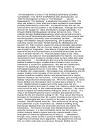
Microencapsulation is the process of enclosing solids, liquids or gases within
envelopes of protective shell materials. It involves the formation of a retentive
wall or shell around the core material. Depending on the method of
microencapsulation employed, the morphology of microparticles produced can
generally be divided into two main categories: matrix (Fig 1a) and reservoir (Fig
1b) types. Matrix-type microparticles are usually termed microspheres, while
those with reservoir-type structures are commonly known as microcapsules.
However, a wide variety of intermediate morphologies are possible, and examples
are illustrated in Figures 1c and d. The typical size range of microparticles is 1 to
2000 µm (Deasy, 1984; Arshady, 1993).
A1. Significance of microencapsulation
Microencapsulation is commonly employed in food and pharmaceutical industries
for a variety of reasons. These include controlled and/or site-specific release of
drugs (Anal et al., 2006; Krishnamachari et al., 2007; Mladenovska et al., 2007),
protection from external environmental conditions like light, moisture and oxygen
(Takeuchi et al., 1992; Lin et al., 1995a; Bustos et al., 2003; Kagami et al., 2003),
reduction of volatile oil or flavour loss (Bhandari et al., 1992; Sheu and
Rosenberg, 1995; Shiga et al., 2001), masking of certain undesirable properties of
the material like unpleasant taste or odour (Weiß et al., 1995; Bruschi et al., 2003),
improving the bioavailability of lipophilic drugs (Jizomoto et al., 1993; Mu et al.,
1
2005) and protection of sensitive components like proteins, enzymes and DNA
from degradation (Johnson et al., 1997; Genta et al., 2001). An additional benefit
in the microencapsulation of liquids or oily materials is the improvement of
handling properties with the conversion of the product from a liquid form to a dry,
particulate system.
(a)
(b)
(c)
(d)
Figure 1. Diagrammatic representation of different microparticle morphologies:
(a) matrix type; (b) reservoir type; (c) polynuclear type; (d) microencapsulated
microcapsules (adapted from Arshady, 1993).
A2. Microencapsulation of oils
Many compounds of interest in the pharmaceutical, food, cosmetic and
agricultural industries are administered or exist in the oily form. As mentioned in
the previous section, hydrophobic drugs can be formulated in an oily carrier or
2
emulsion form for improved bioavailability. Essential oils and flavours are
commonly used as food additives for improving the taste or aroma of the foods to
which they are added (Arshady, 1993; Shahidi and Han, 1993). Lipids and oils
containing polyunsaturated fatty acids are used as food additives and health
supplements (Shahidi and Han, 1993). Some pesticides and animal repellants can
be oils or mixtures of essential oils (Boh et al., 1999; Kulkarni et al., 2000). All
the above compounds can potentially be or are already formulated as
microspheres or microcapsules.
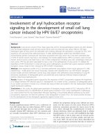
A3. Fish oils and polyunsaturated fatty acids (PUFAs)
In recent years, fish oils have gained popularity not only as nutritional
supplements but also as pharmacological agents with potentially beneficial
clinical effects. They are abundant in long-chain ω-3 PUFAs, mainly
eicosapentaenoic acid (EPA) and docosahexaenoic acid (DHA) (Fig 2), which are
precursors to a group of physiologically important compounds termed eicosanoids.
Eicosanoids are hormone-like substances involved in various biological processes
like blood clotting and modulation of blood pressure and immune responses. EPA
and DHA are also found to be concentrated in human cell membrane
phospholipids, especially those in vital organs like the heart and brain. It was
postulated that with suitable levels of EPA and DHA supplementation, it is
possible to prevent the occurrence or progression of a wide spectrum of disease
states (Shahidi and Wanasundara, 1998; Moyad, 2005).
3
(a)
(b)
O
OH
O
OH
Figure 2. Structures of (a) eicosapentaenoic acid and (b) docosahexaenoic acid.
Numerous experimental and clinical studies have been published on the effects of
EPA and DHA on the cardiovascular system. A prospective, randomized clinical
trial on the effects of EPA and DHA on patients who had experienced a recent
myocardial infarct concluded that cardiovascular mortality was reduced by daily
administration of the ω-3 PUFAs (GISSI-Prevenzione Investigators, 1999). This
finding was also supported by other researchers, who found positive correlations
between ω-3 PUFA supplementation and the reduction in mortality from sudden
cardiac death (Albert et al., 2002; Lemaitre et al., 2003). An expert round table
discussion on the relationship between ω-3 PUFA consumption and coronary
heart disease concluded that drug treatment with 1g/day of ethyl esters of EPA
and DHA in patients who had experienced myocardial infarction was useful in
reducing cardiac mortality. It also suggested that patients with hypertension,
hypertriglyceridemia, or have undergone coronary artery bypass surgery or heart
4
transplantation would benefit from ω-3 PUFA administration (Nordøy et al.,
2001).
The role of ω-3 PUFAs in inflammation and autoimmune diseases has also been
explored. EPA competes with arachidonic acid for metabolic pathways leading to
the production of inflammatory and chemotactic compounds, thereby resulting in
a less pronounced inflammatory response. Many clinical trials have been
conducted to determine the effects of ω-3 PUFA on inflammatory disease states,
especially rheumatoid arthritis, inflammatory bowel disease, asthma and psoriasis
(Horrocks and Yeo, 1999; Calder, 2001; Simopoulos, 2002). It was found that ω-3
PUFA supplementation was generally beneficial to patients with these conditions.
ω-3 PUFAs have also been found to play a significant role in the human brain and
cognitive function even from the foetal stage of life. This could be due to the fact
that DHA is the predominant structural fatty acid in the human brain and retinal
tissue, and is essential for their growth, development and maintenance (Neuringer
et al., 1988; Horrocks and Yeo, 1999; Lauritzen et al., 2001; Kotani et al., 2006).
The role of ω-3 PUFAs in disease states like dementia and Alzheimer’s disease
and psychiatric disorders including depression and schizophrenia has also been
explored. Although positive outcomes were reported in most cases, the focus was
more on ω-3 PUFA supplementation rather than on its usage as a standalone
treatment (Arvindakshan et al., 2003; Morris et al., 2003; Su et al., 2003; FreundLevi et al., 2006; Parker et al., 2006; Sontrop and Campbell, 2006; Das, 2008).
5
Commercially available formulations of EPA- and DHA-containing products are
predominantly purified marine oils filled into soft gel capsules or formulated as
emulsion form. They are generally marketed as health or nutritional supplements
rather than as medicinal products. From the manufacturing point of view, capsules
are relatively expensive as a dosage form compared to tablets. In addition, animal
gelatin sources may pose problems with consumer or patient acceptability due to
dietary or religious reasons. Besides stability issues, the emulsion form is bulky
and less easily or accurately administered than a solid dosage form. Due to their
polyunsaturated nature, EPA and DHA are also prone to oxidation, which can give
rise to rancid and toxic by-products. As such, there is a need to develop alternative
dosage forms for EPA and DHA delivery that are not only easily administered, but
also provide the function of oxidative stabilization.
A3.1 Microencapsulation of fish oils
Fish oils have been microencapsulated using a variety of ingredients and methods
for the purpose of oxidative protection and for ease of incorporation into food
products like enriched bread and infant formula (Kolanowski and Laufenberg,
2006). Spray drying was used to microencapsulate fish oil by a number of
researchers using protein-based wall materials with or without blending with
maltodextrin (Keogh et al., 2001; Hogan et al., 2003; Kagami et al., 2003; Baik et
al., 2004). Modified cellulose (Kolanowski et al., 2004; Kolanowski et al., 2006),
chitosan (Klinkesorn et al., 2005) and derivatized starch (Drusch and Berg, 2008)
have also been employed as wall materials for fish oil encapsulation by spray
drying. Other methods like freeze drying (Heinzelmann and Franke, 1999;
6
Márquez-Ruiz et al., 2000; Klaypradit and Huang, 2008) and enzymatic gelation
(Cho et al., 2003) have also been used.
The different wall materials and encapsulation methods varied in their degrees of
usefulness in terms of their microencapsulating and protective abilities. However,
direct comparisons among the merits of each system were difficult due to the
different oil loadings and characterization methods employed. Oil loadings used
ranged from 25 to 100 %. The encapsulation of higher oil loadings has not been
reported. In addition, there have been no reports on the use of alginate as wall
material for fish oil encapsulation by spray drying.
A4. Methods of oil encapsulation
Many methods have been explored for the purpose of oil encapsulation. They can
generally be classified as chemical or physical processes.
A4.1 Chemical processes
A4.1.1 Complex coacervation
Complex coacervation is a commonly used method for oil encapsulation. It
generally involves the emulsification of the oil within a hydrocolloid solution,
followed by mixing with another oppositely charged hydrocolloid system to form
a liquid polyelectrolyte complex termed the complex coacervate. The coacervate
phase would be deposited around the oil and microcapsules would be formed
through solidification of the coacervate by drying or cross-linking processes
7
(Shahidi and Han, 1993; Gouin, 2004). Various hydrocolloid systems have been
studied, of which the gelatin/acacia system was the most common. It has been
used for the microencapsulation of essential and flavour oils (Flores et al., 1992;
Gouin, 2004; Chang et al., 2006), oily carriers for hydrophobic drugs (Jizomoto et
al., 1993; Palmieri et al., 1999) and ω-3 PUFAs (Lamprecht et al., 2001; Jouzel et
al., 2003).
Other hydrocolloid systems employed include whey protein/acacia (Weinbreck et
al., 2004), globulin/acacia (Ducel et al., 2004), gliadin/acacia (Ducel et al., 2004),
gelatin/gellan gum (Chilvers and Morris, 1987) and gelatin/polyphosphate
systems (Ribeiro et al., 1997). Microcapsules formed from complex coacervation
generally had good oil retention properties. However, loss of water-soluble
components from encapsulated fragrances tended to occur due to the presence of
water in the external phase during microcapsule formation (Flores et al., 1992;
Ribeiro et al., 1997).
A4.1.2 Other processes
Other less commonly used processes include interfacial polymerization (Yan et al.,
1994; Boh et al., 1999), emulsification (Chan et al., 2000), cross-linking (Kulkarni
et al., 2000; Díaz-Rojas et al., 2004; Peniche et al., 2004) and simple coacervation
(Bachtsi and Kiparissides, 1996; Mauguet et al., 2002). Most of the chemical
methods were small-scale and their use in industrial or commercial applications
may be limited by poor scalability, with generally small batch sizes. Some
production methods also required the use of organic solvents, which reduced their
8
attractiveness as a method for microencapsulation of products intended for human
consumption due to the possibility of residual toxicity and environmental concerns.
A4.2 Physical processes
Extrusion has been used for the encapsulation of sunflower oil (Yilmaz et al.,
2001) and flavour oils (Gunning et al., 1999). Freeze drying was found to be
another useful method for oil encapsulation, especially for heat-sensitive materials.
However, long dehydration periods of about 20 h were required. It was used to
microencapsulate fish oil (Heinzelmann and Franke, 1999; Márquez-Ruiz et al.,
2000) and methyl linoleate (Minemoto et al., 1997). Molecular inclusions using ßcyclodextrin have also been used for the encapsulation of lemon oil (Bhandari et
al., 1998; Bhandari et al., 1999) and meat flavour (Jeon et al., 2003). Spray drying
is probably the most commonly used physical process in the industry for oil
encapsulation, and this will be elaborated upon in the subsequent section.
A4.2.1 Spray drying
Spray drying is defined as “the transformation of feed from a fluid state into a
dried particulate form by spraying the feed into a hot drying medium” (Masters,
1991). In the case of oil encapsulation, the feed is usually an emulsion of the oil of
interest as the discrete phase in a continuous phase containing the dissolved or
dispersed wall or carrier material. Matrix-type microspheres are usually produced
when spray drying is used as a method for oil encapsulation.
9
The process of spray drying can be broken down into four stages.
a) Atomization of the feed into a spray of droplets
This is the first stage of spray drying, and involves breaking up the feed by an
atomizer into small droplets that can easily be dried. Different types of atomizers
(rotary wheel, pressure nozzle and pneumatic nozzle) are available to achieve feed
liquid breakdown, and the selection of an atomizer type depends on the
characteristics of the feed and the qualities desired of the final product.
b) Spray-air contact
In this stage, the droplets enter the drying medium and are mixed with the drying
air flow. There are generally two types of feed-drying air flow conditions: cocurrent and counter-current. The former involves the droplets and drying air
flowing in the same direction i.e. entering the dryer from the same end. This is a
commonly used configuration and is advantageous especially for heat-sensitive
materials. In the latter arrangement, the droplets and the drying air enter the dryer
from opposite ends of the dryer. Although it is a more thermally efficient method,
products are subjected to more heating effects. Some spray dryers incorporate
both layouts and are termed mixed-flow dryers.
c) Drying and particle formation
After the droplets come into contact with the drying air, rapid moisture
evaporation takes place. This initially occurs from the droplet surface, with
continuous mass transfer of moisture from within the droplet. Eventually, a dried
shell is formed and moisture evaporation continues at a slower rate until the final
product is formed.
10
d) Separation of product from the drying air
This is the final stage of spray drying where the dried product is collected. Most of
the product is usually collected from the base of the drying chamber through
gravitational effects, while fines entrained in the drying air can be harvested using
a cyclone or filtration system.
Spray drying is a one-step, continuous process, allowing ease of scale-up. It is also
useful for the processing of heat-sensitive materials due to the very short exposure
time of product to heat, which can range in the order of 5 to 100 s (Corrigan,
1995). As such, it is a popular method for the microencapsulation of volatile oils
and flavours (Bertolini et al., 2001; Bylaitë et al., 2001; Beristain et al., 2002;
Apintanapong and Noomhorm, 2003). Many researchers have also used spray
drying as a method to encapsulate polyunsaturated fatty acids, which are sensitive
to heat and oxidation (Minemoto et al., 2002a, b; Kagami et al., 2003; Kolanowski
et al., 2004; Drusch et al., 2006; Drusch and Berg, 2008). Spray-dried
redispersible oil-in-water emulsions have also been studied as a means for
improving the bioavailability of lipophilic or poorly water soluble drugs (Pedersen
et al., 1998; Christensen et al., 2001).
A5. Wall materials for oil encapsulation by spray drying
Wall materials play an important role in oil encapsulation. They are major
determinants of the quality and functionality of the encapsulated product. An ideal
wall material should be highly water soluble, of low viscosity and possess film
forming properties. It should also have sufficient emulsifying ability to produce
11