Synthesis of 5,6,11,12,17,18 hexaazatrinaphthylene nanowires for cathode material in lithium battery
Bạn đang xem bản rút gọn của tài liệu. Xem và tải ngay bản đầy đủ của tài liệu tại đây (3.63 MB, 43 trang )
SYNTHESIS OF 5,6,11,12,17,18-HEXAAZATRINAPHTHYLENE
NANOWIRES FOR CATHODE MATERIAL IN LITHIUM
BATTERY
SU JIE
NATIONAL UNIVERSITY OF SINGAPORE
2014
SYNTHESIS OF 5,6,11,12,17,18-HEXAAZATRINAPHTHYLENE
NANOWIRES FOR CATHODE MATERIAL IN LITHIUM
BATTERY
SU JIE
(MSc), PKU
A THESIS SUBMITTED
FOR THE DEGREE OF MASTER OF SCIENCE
DEPARTMENT OF CHEMISTRY
NATIONAL UNIVERSITY OF SINGAPORE
2014
Declaration
I hereby declare that this thesis is my original work and it has been written by me
in its entirety. I have duly acknowledged all the sources of information which
have been used in the thesis.
This thesis has also not been submitted for any degree in any university
previously.
Su Jie
-T
(_
/.
"t)
)- r. J'L
Signature
')r0 ' 0g 10 lV
Acknowledgement
This work was performed under the supervision of Prof. Loh Kian Ping in
Department of Chemistry, Faculty of Science, National University of
Singapore. I deeply appreciated Prof. Loh for his patient instructions and great
support. Prof. Loh showed me a real scientist’s passion and dedication to work.
The experience in Prof. Loh’s group is a precious treasure in my life. I also
want to express my appreciation to Dr. Su Chenliang and Dr. Peng Chengxin
for their instructions and help. They brought me into a brand new world which
is full of excitement. Working and studying with them benefited me a lot.
They taught me many useful and meaningful things. The way which they work
inspire me and gave me a strong desire to continue my research career in the
future. I want to thank my teammates, Rika and Shiqiang. I also want to
express my gratitude to my labmates in Prof. Loh’s lab.
I want to appreciate the SPORE program to offer me this wonderful
opportunity to become a member of NUS. I also want to thank my family who
have always steadfastly support me.
Last but not least, I want to express my sincere gratitude to National
University of Singapore. It is my great honor to be a member of this Asia’s
leading University. No matter what I will meet in the future, the passion she
showed me will encourage me to keep on fighting until the destination.
II
TABLE OF CONTENTS
Declaration
........................................................................................................................................
I
Acknowledgement
........................................................................................................................
II
TABLE OF CONTENTS
.........................................................................................................
III
Summary
..........................................................................................................................................
V
List of Tables
................................................................................................................................
VI
List of Figures
.............................................................................................................................
VII
List of Abbreviations
...............................................................................................................
VIII
Chapter 1 Introduction
.................................................................................................................
1
1.1 Rechargeable lithium batteries and their challenges
.........................................
1
1.2 Organic materials for electrode in LIBs
................................................................
2
1.3 Previous researches on organic molecules for LIBs’ electrode
materials
..................................................................................................................................
3
1.3.1 Carbonyl containing molecules
..................................................................
3
1.3.2 N containing molecules
.................................................................................
7
Chapter 2 5,6,11,12,17,18-hexaazatrinaphthylene (HAT)
...............................................
9
2.1 Research background
..................................................................................................
9
2.2 Characterizations of HAT
.......................................................................................
10
2.2.1 FT-IR
................................................................................................................
11
2.2.2 UV-Vis spectrum
.........................................................................................
11
2.3 Diffraction pattern of HAT
....................................................................................
12
2.4 Morphology analysis of HAT
................................................................................
13
2.4.1 SEM
..................................................................................................................
13
2.4.2 TEM
..................................................................................................................
14
2.5 Concluding remarks
..................................................................................................
15
Chapter 3 Electrochemical characterizations and cathode performance of HAT
for LIBs
..........................................................................................................................................
16
3.1 Battery assembly strategies
....................................................................................
16
3.2 HAT in EC/DMC system
........................................................................................
16
3.2.1 Cyclic voltammogram curves
..................................................................
16
3.2.2 Charge and discharge performance
........................................................
17
3.2.3 Cycle performance
.......................................................................................
18
3.3 HAT in DOL/DME system
....................................................................................
19
3.3.1 Cyclic voltammogram curves
..................................................................
19
3.3.2 Charge and discharge performance
........................................................
20
3.3.3 Cycle performance
.......................................................................................
21
3.3.4 Rate performance
.........................................................................................
22
3.3.5 Long cycle performance
............................................................................
23
3.4 Concluding remarks
..................................................................................................
24
Chapter 4 Experimental sections
...........................................................................................
26
4.1 Materials and instruments need in this study
...................................................
26
4.2 Synthesis of HAT
............................................................................................
27
4.3 Characterizations of HAT
.......................................................................................
29
3.2 TGA analysis of HAT
..............................................................................................
29
2.3.8 Morphology characterizations
.................................................................
31
4.4 Battery assembly and electrochemical characterizations
.............................
31
III
4.4.1 Battery assembly
..........................................................................................
31
4.4.2 Electrochemical measurements
...............................................................
32
References
.....................................................................................................................................
33
IV
Summary
Organic molecule 5,6,11,12,17,18-hexaazatrinaphthylene (HAT) nanowires
were synthesized and applied as cathode material for lithium ion batteries. The
results demonstrate that the molecule has an outstanding cathode performance
in the electrolyte consisting of LiTFSI dissolved in 1,3-dioxolane (DOL) and
1,2-dimethoxyethane (DME). During the charge-discharge process, two
electrochemical reactions occur with the redox at 1.5 V and 2.5 V, displaying
six electrons transfer. Electrochemical study shows that the molecules have
several competitive properties, such as high capacity, stable cycling and high
coulombic efficiency. The molecules exhibit a capacity of about 260 mAh/g at
a current density of 100 mA/g. In addition, the molecules afford a capacity of
200 mAh/g at a current density of 400 mA/g, and this performance has been
tested 500 cycles. It has a coulombic efficiency close to 100% and high
capacity retention of 91% after 500 cycles.
Keywords: Organic cathode materials, nanowires, lithium ion batteries,
performance
V
List of Tables
Table 1. Materials needed in this study. ....................................................... 26
Table 2. Instruments needed in this study. .................................................... 26
Table 3. Elemental analysis results of synthesized products ........................ 29
VI
List of Figures
Figure 1. Mechanisms of carbonyl containing molecules for LIBs ................ 3
Figure 2. Early carbonyl containing molecules for LIBs. ............................... 4
Figure 3. Representatives of polymerization of small molecules. .................. 6
Figure 4. Representatives of salt formation molecules. .................................. 7
Figure 5. N containing molecules for LIBs. ................................................... 7
Figure 6. Molecular structure of HAT ............................................................ 9
Figure 7. Charge-discharge process of HAT ................................................ 10
Figure 8. FT-IR of HAT................................................................................ 11
Figure 9. UV-Vis of HAT. ............................................................................ 12
Figure 10. XRD of HAT ............................................................................... 13
Figure 11. SEM images of HAT ................................................................... 14
Figure 12. TEM images of HAT ................................................................... 15
Figure 13. CV of HAT in EC/DMC. ............................................................ 17
Figure 14. Charge-discharge of HAT in EC/DMC. ...................................... 18
Figure 15. Cycling performance of HAT in EC/DMC. ................................ 19
Figure 16. CV of HAT in DOL/DME........................................................... 20
Figure 17. Charge-discharge of HAT in DOL/DME. ................................... 21
Figure 18. Cycling performance of HAT in DOL/DME. ............................. 22
Figure 19. Rate performance of HAT in DOL/DME. ................................... 23
Figure 20. Long cycle test of HAT at 200mAh/g. ........................................ 23
Figure 21. Long cycle test of HAT at 400mAh/g. ........................................ 24
Figure 22. Pathway of synthesizing HAT. .................................................... 27
Figure 23. Synthesized HAT......................................................................... 27
Figure 24. 1H NMR of HAT......................................................................... 28
Figure 25. 13C NMR of HAT ....................................................................... 28
Figure 26. TGA results of HAT by weight loss percentage. ........................ 30
VII
List of Abbreviations
HAT: 5,6,11,12,17,18-hexaazatrinaphthylene
LIBs: Lithium Ion Batteries
MO: Molecular Orbital
LUMO: Lowest Unoccupied Molecular orbital
NMR: Nuclear Magnetic Resonance
TGA: Thermo Gravimetric Analyzer
FT-IR: Fourier Transform Infrared Spectroscopy
UV-Vis: Ultraviolet-Visible Spectroscopy
XRD: X-Ray Diffraction
SEM: Scanning Electron Microscope
TEM: Transmission Electron Microscope
DMF: N, N-Dimethylformamide
NMP: Methyl-2-pyrrolidone
VGCF: Vapor Growth Carbon Fibre
EC: Ethylene Carbonate
DMC: Dimethyl Carbonate
DOL: 1,3-dioxolane
DME: 1,2-dimethoxyethane
CV: Cyclic Voltammograms
VIII
Chapter 1 Introduction
1.1 Rechargeable lithium batteries and their challenges
The global demand for energy has been rising exponentially over the time.
Rechargeable lithium ion batteries have dominated the market for a long time for
portable electronics with high energy densities.[1, 2] However, like any other
materials, LIBs has limitations that have been overlooked due to their greater
advantage in daily usage. These limitations of LIBs are related to the cathode
materials.[3] Currently, inorganic materials dominate the market due to their
systematic mechanism research, mature technologies and stable performances. For
example, lithium cobalt oxide and lithium iron phosphate are widely used in various
LIBs.
However, these inorganic materials have their own shortcomings. Some of these
materials require elements that are not naturally abundant, which renders these
materials unsustainable. As a consequence, the price of inorganic materials will
skyrocket in the future. Furthermore, waste electrode materials contain heavy metal
ions, which are the main culprit in environmental pollution. The biggest challenge of
inorganic electrode is that their energy densities are difficult to improve. Even though
many materials have a theoretical capacity of 300 mAh/g, the actual attainable
capacities are half of that. Thus, discovering new cathode materials for rechargeable
batteries with high capacity and power, free from heavy metals, is an important
research field.
1
1.2 Organic materials for electrode in LIBs
It is attractive to consider the use of organic molecules as candidate electrode
materials for rechargeable LIBs. Compared with inorganic molecules and other
materials, on which researches have reached their maturity, organic materials offer
several advantages over their counterparts, i.e. lower price, elemental abundance and
higher specific capacity et al.
However, due to stability issues, the development of organic molecules is slow after
the first report on organic electrode.[3] Now, with the urgent demand for novel
electrode materials, more researchers are focusing on organic molecules. Some early
studies have investigated a few specifically designed organic molecules for electrode
use. They showed many advantages.
Higher theoretical capacities and higher actual capacities. Usually organic
molecules have more active sites for lithium ions;
Potential low-cost and safe raw materials. Many molecules can be obtained in a
variety of pathways, even biomass transformation;[4]
Recycling and eco-friendly possibilities. The electrode materials can be enriched
and transformed into other materials by different chemical methods for recycling
purpose.
These advantages make organic molecules ideal candidates for recyclable, low carbon
footprint and safe LIBs electrode materials. Therefore, it’s necessary and promising to
develop electrode materials from organic molecules.
Based on previous studies, we draw a conclusion that testing a suitable organic
electrode material involves three steps: molecular design, material synthesis and
characterization and electrochemical activity tests.
2
1.3 Previous researches on organic molecules for LIBs’ electrode materials
Previous researchers have studied different organic molecules for LIBs. Two groups
of electrochemical active organic molecules are widely investigated recently: Organic
carbonyl containing molecules and N containing molecules.
1.3.1 Carbonyl containing molecules
Carbonyl is a common functional group that shows apparent oxidative ability. The
mechanism scheme is shown below. In the presence of appropriate stabilizing R
groups, the carbonyl group undergoes one-electron reduction to form a radical
monoanion. When several carbonyl groups are conjugatedly connected, the single
electrons generated during reduction could combine intramolecularly to form
multivalent anions.
Figure 1. Mechanisms of carbonyl containing molecules for LIBs
Carbonyl compounds for cathode materials goes back to 1960s when Williams first
used dichloroisocyanuric acid in primary lithium battery.[5] It showed a rough charge
capacity about 120 mAH/g with a potential ranging from 3.0 to 3.5 V. But the
discharge procedure was irreversible because of its chemical formation. Then Alt
investigated chloranil,[6] the carbonyl secondary lithium battery cathode material, for
the first time. After that, many carbonyl molecules were used as electrode materials.
3
However significant solubility in electrolyte caused poor cyclability of these
molecules.
Figure 2. Early carbonyl containing molecules for LIBs.
To
address
the
solubility
issues
by
designing
large
molecules,
nonylbenzo-hexaquinone (NBHQ) (3), was first reported for its reasonable cycle
performance by Pistoia. [7] With large molecular weight and planar structure, NBHQ
exhibited reversible capacity of 125 mAh/g. The theoretical capacity of NBHQ was
489 mAh/g, assuming that all 12 electrons participated fully in the redox reaction.
However, only three electrons were involved in the reaction. NBHQ was then no
longer considered as promising because of its low capacity (only 25% of theoretical
value) at that time. In order to solve this intrinsic shortcoming of carbonyl molecules,
several other strategies have been proposed.
Polymerization and oligomerization
Since most of the carbonyl containing molecules are small with high solubility, one of
the solutions is to immobilize the molecule. The direct way is polymerization or
oligomerization without destroying the electrochemically active functional groups.
4
Haas reported a poly-quinone (4) in 1999 using PAn as backbones.[8] This method
significantly decreased the solubility and enhanced the conductivity at the same time.
The PAn-polyquinone’s initial discharge approached the theoretical capacity of 290
mAh/g. After capacity degradation for the first ten cycles, it gradually converged at
about 200 mAh/g. Then, several polyquinones, as shown below, were evaluated, with
better performance than earlier molecules due to solubility suppression.
On the other hand, it is also possible to bind small molecules to polymer chains to
increase
the
stability.
Yoshida
and
his
co-workers
successfully
bound
pyrene-4,5,9,10-tetraone (PYT) to polymethacrylate (PPYT, 5), which showed a
specific capacity of 231 mAh/g. It retained 83% capacity after 500 cycles, which was
95.21% higher than PYT small molecules.[9] In addition, 90% capacity was retained
when current density reached 30C. This is one of the most promising organic
cathodes for LIBs recently.
Aside from the polymerization method, direct sulfurization of some carbonyl
molecules
could
also
decrease
3,4,9,10-perylene-tetracarboxylicacid-diahuride
(PTCDA)
the
(6)
solubility.
was
widely
investigated due to its electrochemical activity and planar structure. Similar to other
molecules, solubility is the main concern. Therefore, Sun and his co-workers
polymerized PTCDA by using S as the linker to form thiother bonds between
perylene rings, resulting in improvement of its stability and conductivity.[10]
Although the capacity was relatively low, which was mainly caused by the molecular
weight of PTCDA, this method can be applied to other small molecules to enhance
the electrochemical performance.
5
Figure 3. Representatives of polymerization of small molecules.
Salt formation
Other than polymerization and oligomerization, the solubility of carbonyl containing
molecules can also be suppressed by increasing their polarities via salt formation.
The first study of such method was dilithiated 2,5-dihydroxy-1,4-benzoquinone
(7).[11] The capacity dropped to 23% at the first 10 cycles, but it showed good
stability as a small molecule. Later, Poizot used dilithiated oxcarbon (8), which
showed a high capacity of 580 mAh/g.[3] But it failed to retain such high capacity
after 25 cycles (dropped to about 50% of its initial capacity). From the examples
above, a trend is found that multiple charge creation is the key to suppression of
dissolutions.
6
Figure 4. Representatives of salt formation molecules.
1.3.2 N containing molecules
Figure 5. N containing molecules for LIBs.
Another group of electrochemical active molecules is N-containing molecules.
Researches in these molecules have only started in recent years.[12] Different from O
atom in carbonyl molecules, N atom has more structural variety in different molecules,
for an N atom has one more electron than an O atom. This character makes N
containing molecules could exist as two types. One is molecules with C=N double
bonds, whose redox reactions occur between neutral state and negatively charged. The
other type is molecules only with C-N bonds, whose redox reactions occur between
neutral and positively charged. Therefore, the performances are different among the
molecules. The mechanisms of how these molecules work are not clear. One
commonality is that conjugated amine structure exists in these molecules. Among
these molecules, the simplest and extensively studied one is triazine, a bipolar
7
molecule. The bipolar property causes triazine to exhibit large reversible capacity of
150 mAh/g during charge and discharge.[13, 14] Although PTPAn’s (10) capacity
was low (only 109 mAh/g), but it had a good rate performance (up to 20C) and cycle
performance (up to 1000 cycles).[15]
Despite these efforts, there is still much room to improve the electrochemical
performance of organic cathode materials. Meanwhile, the lithiation and delithiation
mechanisms of N containing molecules is not clear and until now, which will put
some hurdles on the way of optimizing the electrochemical performance of organic
electrodes. Therefore, it is necessary to investigate their properties to develop novel
molecules and explore the mechanisms at the same time.
8
Chapter 2 5,6,11,12,17,18-hexaazatrinaphthylene (HAT)
To study 5,6,11,12,17,18-hexaazatrinaphthylene (HAT), a candidate material for LIBs,
it is important to collect basic information about the molecule. Several
characterizations were carried out on the synthesized molecule.
2.1 Research background
HAT, shown in Figure 6, is the prototype of a group of organic molecules, which
were widely researched for organic electronic applications.[16] Based on previous
X-Ray studies, it has a planar structure with six N atoms around the centre of the
molecule and it exhibits D3h symmetry. Six C=N indicate the potential active sites.
Figure 6. Molecular structure of HAT
Previous MO calculation study indicated that its next lowest unoccupied molecular
orbitals (LUMOs) are doubly degenerated and their energy levels are close to its
LUMO energy level, which means a potential redox reaction with six-electron
migration. Thus, HAT is likely to be a promising candidate for electrode material with
a theoretical capacity of 418 mAh/g, which makes it more attractive.[17]
HAT has been studied for LIBs cathode by Takayuki and his co-workers. At the
beginning, the charge-discharge capacity was closed to theoretical value by less active
material proportion (10% wt), but the performance was unstable due to its capacity
9
decrease within the first 20 cycles. It only retained a capacity of about 200 mAh/g
with a poor coulombic efficiency in the following cycles. They attempted to improve
the performance by incorporating functional groups (e.g. Cl, Br), but the results were
not satisfactory enough.
A systematic characterization and mechanistic study has to be investigated to
understand the instability of HAT and other similar molecules. In this thesis, we
relook at HAT and redevelop it as the target material for electrode material to
understand more about N-containing molecules as lithium ion battery cathode
materials.
Figure 7. Charge-discharge process of HAT
Figure 7 depicts the possible charge-discharge mechanism for this molecule, based on
its structural analysis. Every nitrogen atom is assumed to participate in the redox
reaction, hence involving 6 electrons.
2.2 Characterizations of HAT
The properties of HAT have characterized by NMR, elemental analysis and TGA,
which are shown in the experiment section.
10
2.2.1 FT-IR
756
1077
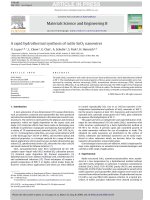
Figure 8. FT-IR of HAT.
The FT-IR results are displayed in Figure 8. C-H bond vibration is ascribed to a sharp
peak at 756 cm-1and weak peaks around 3000 cm-1. Band in green, ranging from 1000
to1200, might be assigned to conjugate vibration by carbon bones. Band from 1500 to
1650 cm-1 generates from C=N double bond and C=C double bond, which are
highlighted in blue.
2.2.2 UV-Vis spectrum
The UV-Vis analysis is shown in Figure 9. Two absorption peaks are clearly seen at
382nm and 402nm, which can be assigned to the C=N bonds in the molecules. The
absorption property also indicates that this molecule has strong absorption near visible
region.
11
Figure 9. UV-Vis of HAT.
2.3 Diffraction pattern of HAT
As shown in Figure 10, the powder XRD results can be clearly observed. Peaks
appear at 24 degree and 27 degree, which may reveal the stacking structure. However,
the intensities of these signals are weak, indicating that the structure is
inhomogeneous in the synthesized molecules. It is worth pointing out that there were
also sharp peaks at 8.9 degree and 15.7 degree. These peaks might be related to the
ordered structure existing within the molecules.
12
15.7
8.9
Figure 10. XRD of HAT
2.4 Morphology analysis of HAT
2.4.1 SEM
As shown in Figure 11, HAT nanowires are arranged lay by layer without certain
directions under lower magnification (A and B). The widths of these nanowires range
from 80nm to 200nm. The lengths are longer than 5µm. The wire structure is slightly
ordered structure, which might be caused by π-π stacking among the molecules and
revealed in the diffraction results.
The product can be spontaneously self-assemble form nanowire under different
solvents, including NMP, methanol and DMF. However, it becomes amorphous in
chloroform.
13
Figure 11. SEM images of HAT
2.4.2 TEM
More structural details can be observed from the TEM images in Figure 12. It
confirms the nanowire shape of the synthesized HAT. At the edge of the nanowire,
the evidence of stacking can be seen (red circles in A and B).
The width of the wire is about 100nm. It is noticeable that some lattice-pattern parts
can be observed at the edges of wires (red circles in C). These parts are supported by
SEAD pattern (D). However, the lattice-pattern parts are not seen at the every
nanowire, which suggests that the material is amorphous or polycrystalline in layered
manner.
14
Figure 12. TEM images of HAT
2.5 Concluding remarks
1. The HAT molecules were successfully characterized and verified;
2. Different characterizations were conducted to explore the property;
3. FT-IR and UV-Vis supports the structure confirmation of the synthesized
molecules;
4. It has nanowire morphology, which could be seen via SEM and TEM. But the
ordered structure was not homogeneous;
5. In this study, the morphology of HAT was nanowire. More study should be carried
out in the future work to under the co-relation between capacity and morphology.
15