Collision avoidance for unmanned aerial vehicles
Bạn đang xem bản rút gọn của tài liệu. Xem và tải ngay bản đầy đủ của tài liệu tại đây (9.51 MB, 129 trang )
COLLISION AVOIDANCE
FOR UNMANNED AERIAL VEHICLES
TAN HAN YONG
B.Eng.(Hons), NUS
A THESIS SUBMITTED
FOR THE DEGREE OF MASTER OF ENGINEERING
DEPARTMENT OF MECHANICAL ENGINEERING
NATIONAL UNIVERSITY OF SINGAPORE
2008
Acknowledgement
ACKNOWLEDGEMENT
The author wishes to express sincere appreciation for the assistances given by the
following persons in carrying out the work successfully:
Associate Professor Gerard Leng (National University of Singapore), supervisor of
the project, for his patience, advice and guidance in the project.
Mr. Oi Tze Liang (fellow researcher and team mate on the project) for his patience,
effort and contribution to this project.
Mr. Teoh Weilit (fellow researcher and team mate on the project) for his contribution
to this project.
Mr. Kam Mun Loong (fellow researcher in Cosy Lab) for his assistance and
contribution to this project.
Mr. Asfar (fellow researcher in Cosy Lab) for his assistance and contribution to this
project.
The technical staff of the Dynamics Laboratory namely: Ms Amy, Ms Priscilla, Mr.
Ahmad and Mr. Cheng. For their equipment and technical support in the project.
I
Table of Content
TABLE OF CONTENT
TITLE PAGE…………………………………………………………………..
ACKNOWLEDGEMENTS................................................................................ I
TABLE OF CONTENT.............................................................……................. II
SUMMARY…………………………………………………………………….
V
LIST OF FIGURES …………………………………………………...............
VII
LIST OF TABLES……………………………………………………………..
IX
CHAPTER 1: LITERATURE SURVEY …………………………………….
1
1.1 Chapter Summary…………………………………………………………...
9
CHAPTER 2: DESIGN AND ANALYSIS OF COLLISION AVOIDANCE 11
ALGORITHM
2.1 Proportional Navigation law in Collision Avoidance………………...……..
11
2.2 Analysis of Collision Avoidance Algorithm………………………………... 19
2.2.1 Line of Sight Rate Sensor……………………………………………..
20
2.2.2 Range and Heading Sensors ………………………………………….. 22
2.3 Chapter Summary…………………………………………………………...
26
CHAPTER 3: COLLISION AVOIDANCE SIMULATION
VALIDATION
27
3.1 Measurable Variables……………………………………………………….. 27
3.1.1 Range Reading, R……………………………………………………..
28
3.1.2 Obstacle Heading Angle, ζ …………………………………………...
28
3.2 Simulation Models…………………………………………………………..
29
3.2.1 Simulated UAV Dynamics Model…………………………………….
31
3.2.2 Simulated Collision Avoidance Model ……………………………….
34
3.3 Simulation Results for Collision Avoidance Performance…………………
36
3.4 Chapter Summary…………………………………………………………...
38
CHAPTER 4: CAS ARCHITECTURE & IMPLEMENTATION…………. 40
II
Table of Content
4.1 Flight Platform Information………………………………………................
40
4.2 UAV Flight Computer ……………………………………………………..
42
4.2.1 PC104 3-stack Configuration ………………………………………… 43
4.2.2 Micropilot Autopilot ………………………………………………….
44
4.3 CAS Sensor Selection: Sonar Sensor ………………………………………. 44
4.3.1 Sonar Sensor Selection………………………………………………... 44
4.3.2 Sonar Sensor with PC104 Setup………………………………………
45
4.3.3 Sonar Sensor Array Design …………………………………………... 45
4.3.3.1 Single Sonar Sensor Max Range & Field of View Experiment
45
4.3.3.2 Sonar Array Design …………………………………………... 47
4.3.4 Sonar Array CAS Performance Verification………………………….. 49
4.3.4.1 Ground Test Stage 1: Sonar Ranging with Engine running at
idle
49
4.3.4.2 Ground Test Stage 2: Sonar Ranging with Engine running at
just before takeoff
51
4.3.4.3 Flight Test Stage 1: Sonar Ranging with UAV at hover ……... 52
4.3.4.4 Preliminary CAS Sonar Array Conclusion…………………...
53
4.3.5 Sonar Array Interference Investigation ………………………………. 54
4.3.5.1 Sonar on Ground Test ………………………………………...
55
4.3.6 Sonar Array Interference Conclusion ………………………………… 56
4.4 CAS Sensor Selection: Laser Range Finder………………………………...
57
4.4.1 Laser Range Finder Specifications……………………………………
57
4.4.2 Laser Range Finder Flight Test Performance Validation……………..
58
4.4.2.1 Calibration: LRF Calibration Experiment ……………………. 58
4.4.2.2 Flight Test: LRF Functional Experiment……………………..
59
4.5 CAS Architecture……………………………………………………………
61
4.5.1 Collision Avoidance Algorithm System Design………………………
61
III
Table of Content
4.5.2 Servo Sweeping Mechanism…………………………………………..
63
4.5.3 CAS Controller Selection……………………………………………..
66
4.5.4 Gyro Controlled Pitch Stabilised Mount……………………………… 70
4.6 Chapter Summary…………………………………………………………...
74
CHAPTER 5: FIELD VALIDATION ………………………………………. 76
5.1 Field Validation Setup………………………………………………………
76
5.1.1 Video Positioning – Wireless Camera………………………………...
76
5.1.2 Video Positioning – Grid Design……………………………………...
77
5.1.3 Grid Design Setup……………………………………………………..
79
5.2 Field Validation Experiments……………………………………………….
80
5.2.1 Collision Avoidance Algorithm Functionality Test…………………..
80
5.2.2 Varying gain, k value experiments……………………………………
83
5.2.3 Image Analysis………………………………………………………..
84
5.2.4 Field and Simulation Results………………………………………….
87
5.2.4.1 Gain, K value = 1……………………………………………...
87
5.2.4.1 Gain, K value = 2……………………………………………...
89
5.2.4.1 Gain, K value = 3……………………………………………...
91
5.2.4.4 Results comparison……………………………………………
92
5.3 Chapter Summary…………………………………………………………...
93
CHAPTER 6: CONCLUSION……………………………………………….. 94
REFERENCES ………………………………………………………………... 96
APPENDIX…. …………………………………………………………………
100
IV
Summary
SUMMARY
Collision avoidance for Unmanned Air Vehicles (UAV) is a necessity if the UAV is
to fly in an area whereby the terrain is unknown. Collision avoidance is a field widely
researched on especially amongst the robotics community. But most of the existing
collision avoidance algorithms require knowledge of terrain and even the location of
the obstacles with respect to the robot.
This project seeks to verify a collision avoidance algorithm implemented onto an
actual hardware system for the UAV. The terrain and obstacles are unknown to the
UAV before flight and collision avoidance is expected of the UAV using information
relayed only through onboard sensors. Literature survey of existing works on collision
avoidance and collision avoidance in UAVs, revealed a particular study that
approached collision avoidance from a missile guidance point of view and hence is
especially applicable to flight platforms maneuvering in an unknown terrain. The
result is a modified version of the Proportional Navigation (PN) guidance law that
serves as a collision avoidance algorithm.
A thorough theoretical study of the collision avoidance algorithm based on PN
guidance was conducted, detailing how the information required for the collision
avoidance can be obtained from currently commercially available sensors that can be
mounted onboard and to put the information to good use in a collision avoidance
system (CAS). This is then followed by a simulation of the selected UAV flight
platform together with the designed CAS system in place. Simulation helped
determine the optimum collision avoidance gain, k value of 2 that should be used for
V
Summary
the actual flight test. The simulation also provided results of simulated flight paths
that are to be verified with actual field testing.
A flight platform with the sensory and control equipment necessary for implementing
the PN collision avoidance algorithm is put together to realize the algorithm in actual
hardware. A section is dedicated to detailing the specifications of the hardware and
the sensors that are used to put the CAS system together. This is followed by a write
up of the actual field test carried out. The results of the field testing was then collected
and compiled for a comparative study between the simulated flight path and the actual
flight path of a collision avoidance run is similar. This is to determine if the actual
hardware system with an implemented CAS system performs as well as the simulated
results.
Eventually, the comparative study shows that the field results that are collected have
errors that are within a 4% range for k values 1 and 2 and a maximum error of 7.6%
was recorded for k = 3. Considering the complexity of the outfield experiments, the
outfield results error are within a small range and considered to agree with the
simulation results as obtained, verifying a working CAS system in hardware.
VI
List of Figures
LIST OF FIGURES
Figure 2.1: Collision Avoidance Scenario……………………………………...
12
Figure 2.2: Graph of ρmin vs (180o - ψo )………………………………………..
24
Figure 2.3: Plot of Possible Flight Paths……………………………………….. 25
Figure 3.1: Simulation Window Layout………………………………………..
30
Figure 3.2: Helicopter PID Closed Loop……………………………………….
34
Figure 3.3: Variables Measured During Simulation……………………………
35
Figure 3.4: Simulated Collision Avoidance Flight Path with Gain, k value = 1
36
Figure 3.5: Graph of Percentage Error vs k value……………………………… 37
Figure 4.1: UAV Flight Computer Mounted…………………………………...
41
Figure 4.2: Equipment Layout in Flight Computer Box………………………..
42
Figure 4.3: Sonar Array Design………………………………………………...
47
Figure 4.4: Sonar sensor array range and field of view………………………..
48
Figure 4.5: Sonar Sensor Circuitry Layout…………………………………......
48
Figure 4.6: Optilogic RS100 Laser Range Finder……………………………… 57
Figure 4.7: RS100 Calibration Curve…………………………………………..
59
Figure 4.8: 1st RS100 LRF Flight Test…………………………………………. 60
Figure 4.9: Collision Avoidance Algorithm Flowchart………………………...
62
Figure 4.10: Servo Specification……………………………………………….. 63
Figure 4.11: CAS Minimum Obstacle Size…………………………………….
64
Figure 4.12: RS-100 on Servo………………………………………………….. 64
Figure 4.13: Actual Lab Layout………………………………………………...
65
Figure 4.14: RS100 Room Profile Result………………………………………
66
Figure 4.15: Basic Stamp BS2X Controller……………………………………. 67
VII
List of Figures
Figure 4.16: CAS System design with BS2X Controller………………………. 68
Figure 4.17: New CAS Hardware Setup………………………………………..
69
Figure 4.18: Gyro Specification………………………………………………... 71
Figure 4.19: Gyro linked stablised mount……………………………………… 72
Figure 4.20: Complete CAS System Design…………………………………… 73
Figure 5.1: Wireless Camera Attached onto UAV Skid………………………..
77
Figure 5.2: Grid Design………………………………………………………...
78
Figure 5.3: Theodolite………………………………………………………….. 79
Figure 5.4: Actual Grid Setup Outfield………………………………………… 80
Figure 5.5: Collision Avoidance Maneuver to the Right of Obstacle………….. 81
Figure 5.6: Collision Avoidance Maneuver to the Left of Obstacle……………
82
Figure 5.7: Screen Capture of Flight Video…………………………………….
84
Figure 5.8: Measurements made on Screen Capture of Flight Video…………..
85
Figure 5.9: UAV Position Correction Calculation……………………………... 86
Figure 5.10: Corrected Calculation on Screen Capture…………………….......
86
Figure 5.11: Simulated and Actual Flight Path Comparison for Gain, k = 1…... 87
Figure 5.12: Simulated and Actual Flight Path Comparison for Gain, k = 2…... 89
Figure 5.13: Simulated and Actual Flight Path Comparison for Gain, k = 3…... 91
VIII
List of Tables
LIST OF TABLES
Table 3.1: Gains obtained via outfield experimentations…………………………. 33
Table 4.1: Function of Each Component in Flight Computer…………………….. 43
Table 4.2: Flight Computer Controller Details……………………………………
43
Table 4.3: Sonar Sensor Comparison Chart………………………………………. 44
Table 4.4: Max range values of sonar sensor……………………………………... 46
Table 4.5: Sonar sensor field of view……………………………………………..
46
Table 4.6: Results for Sonar Ranging with Engine Running at Idle……………… 50
Table 4.7: Results for Sonar Ranging with Engine Running at Just Before Takeoff
52
Table 4.8: Experiment Comparison Chart………………………………………...
54
Table 4.9: Sonar Interference Summary Table……………………………………
56
Table 4.10: RS100 LRF Specifications…………………………………………… 57
Table 5.1: Varying Gain, k Experiments………………………………………….
83
Table 5.2: Comparison of Field and Simulation Data for Gain, k =1…………….. 88
Table 5.3: Comparison of Field and Simulation Data for Gain, k =2…………….. 89
Table 5.4: Comparison of Field and Simulation Data for Gain, k =3…………….. 90
IX
Literature Survey
CHAPTER 1 - LITERATURE SURVEY
The main objective of this project is to develop a collision avoidance algorithm for an
autonomous Unmanned Aerial Vehicle (UAV). The algorithm should be able to steer
the UAV away from stationary obstacles that are unknown to the UAV initially. Thus,
it should have onboard sensors that allow the UAV to sense and avoid the obstacle. In
this chapter, a review of some of the related work will be discussed.
Before moving to collision avoidance in aerial vehicles, a study of the collision
avoidance algorithms that have been developed for ground robots was conducted to
gain further understanding of the subject matter of collision avoidance. One of the
earlier works on collision avoidance was conducted by [1]. [1] showed that a low
level control system coupled with sensory information was sufficient to perform basic
collision avoidance in real-time. The algorithm that was proposed in [1] is termed the
potential field method and was first implemented into robotics in this research. This is
not as competent a system but required much less computational power than works
whose approach to collision avoidance has been a higher level path planning
algorithm.
In a later work, [2] presented a reactive collision avoidance algorithm which takes
into account the dynamics of the hardware system that the algorithm was
implemented on. [2] implemented 2 different collision avoidance navigation
algorithms, namely the Nearness Diagram Navigation and the Potential Field Method
on a Nomadic XR4000 robot. The 2 different algorithms were algorithms that
originally did not take into account the dynamics of the system that it was
1
Literature Survey
implemented on. [2] incorporated reactive navigation into these 2 algorithms and
showed in hardware demonstration with the XR4000 that it was possible to achieve
(1) collision free navigation during execution run and (2) was able to give the
guarantee of stopping the robot safely with an emergency stop policy.
Sensor inaccuracy is addressed in [3] which incorporated 2 different algorithms. [3]
incorporated the Certainty Grid for obstacle representation and Potential Field for
navigation, resulting in the approach entitled Virtual Force Field. Although the sensor
that was used was the sonar sensor and it was incorporated for a ground robot, the
concept of virtual force field is a concept worth considering if the sensor used for the
UAV has a high inaccuracy rate.
In [4], a laser scanner was used to provide sensory information of the obstacle that is
in the robot’s path. The laser scanner information provides information of the obstacle
that helps the robot to plot an optimal path around the obstacle and achieving the final
destination but with a slightly altered path from the original intended path. [4]
provides a good insight to the usage of the laser scanner as a sensor for detecting
obstacles onboard a platform.
Having gathered some concepts in collision avoidance work previously done on the
ground robots and manipulators, the literature survey moves into research on the work
done for collision avoidance algorithms and sensors that are implemented on flight
platforms on unmanned aerial vehicles. There have been a substantial amount of
research on collision avoidance path planning using GPS signals to relate the position
2
Literature Survey
of the UAV to avoid known obstacles. As this project’s aim is navigating in an
unknown terrain, the use of onboard sensor and reactive algorithms would be the
focus of the remaining section of the literature survey.
A framework to approach collision avoidance is introduced in [10]. The research done
here in [10] explores the technical requirements of an unmanned aerial vehicle and
interestingly divides the space around the UAV into 2 zones. The first and the larger
zone is the temporal sphere of deconfliction and the second inner and closer sphere is
the temporal sphere of collision avoidance. Deconfliction according to [10] describes
a manoeuvre that eliminates the threat of a potential collision, but not requiring the
UAV to make drastic manoeuvre to avoid the obstacle so as to replan the initial flight
path. Collision avoidance is the opposite, requiring drastic actions and changes to the
flight paths. This is an interesting concept and could be worthwhile to explore if a
sensor of long enough range can be used. [10] also explores creating a set of laws for
the UAV which are an adaptation of the 3 laws of robotics. [10] also moves on to
describe certain technical requirements like data link between UAV and the grounds
and various sensors that could be mounted onboard to provide the necessary sensory
information to achieve deconfliction and collision avoidance.
An approach to collision avoidance in UAVs is to make use of cameras mounted to
the front of the UAV to monitor obstacles that may appear in the flight path of the
UAV. [5] explores this by having a single camera to detect obstacles in front of the
UAV. As only stereo vision can provide range to the visually detected obstacle, [5]
makes use of a sequence of images and optic flow line calculations to determine the
range of the obstacle from the UAV. This is a rather novel approach as it is
3
Literature Survey
particularly suited to flight platforms that do not have the adequate payload to operate
a 2 camera stereo vision system onboard.
And in [6], 2 more image processing algorithms were used to process the image
obtained from onboard a UAV to determine the presence of obstacles. [6] proposes
that these systems can be installed onto current UAV to achieve the “sense and avoid”
awareness using these computer vision and image processing algorithms. [6] claims
that the tests done on such vision systems coupled with an appropriate image
processing algorithm is able to achieve first detection at up to 6.5km, which is a much
higher range that what an alert human observer can achieve.
[7] approached the collision avoidance problems using the same idea of image
processing. The research focuses on the meeting the FAA regulations on unmanned
aircraft to be able to sense and avoid local air traffic sufficiently so as to be
comparable to the see and avoid requirements of manned aircraft. [7] uses optical
sensors that operate in the infrared band to detect obstacles. This system is mounted
onboard the Global Hawk and Predator UAVs and achieve results that had the
potential to meet the FAA requirements.
[8] acknowledges that high computational requirement remains the biggest hurdle for
using vision based systems to provide sensory information on obstacles. In turn, [8]
proposes a similar concept to [5] and uses monocular images to provide sensory
information on obstacles, reducing the computational power that is required onboard
the UAV. [8] achieves this through another algorithm which is the feature density
distribution analysis. With this algorithm, the UAV can recognise some of the features
4
Literature Survey
as obstacles and perform collision avoidance. The novelty in this approach is that it
does not require accurate feature extraction of the images and thus is able to
drastically reduce the complexity of the image processing algorithm. For a small scale
UAV with limited payload which translates to less sensitive optical sensors and less
computational power, it is possible to achieve collision avoidance.
The complexity of the obstacles that vision based systems can differentiate depends
very much on the algorithms that process the images. Very often, near invisible
obstacles escape the processing and register as no obstacles. An example would be
power lines that are hardly visible to the human from the air, not to mention vision
systems. [9] proposes a image processing algorithm that is designed to detect thin
obstacles such as power lines and wires.
Another approach to collision avoidance without the use of the vision based sensory
information is the use of radar technology. [11] explores the use of a radar sensor to
detect obstacles in the path of the UAV. A conceptual radar design is used in
simulations of collision avoidance with a stationary obstacle. The radar simulation
was able to detect obstacles in it’s path with a 90% probability, subjected to the
designed radar and specifications. [11] shows that radars could be a viable solution to
the complex vision based systems.
In [12], data fusion of multiple sensors was investigated and used as a means to
provide collision avoidance. The sensors that were used consists of pulsed radar, 2
infrared cameras and 2 normal video cameras. With this amount of sensory
information, a data fusion algorithm was devised which is an adaptation of Kalman
5
Literature Survey
filter. [12] did a comparative study of 3 different algorithms, namely, Conventional
Filter in Rectangular Coordinates, Conventional Filter in Spherical Coordinates, and
Extended Filter in Rectangular Coordinates. The extended filter in rectangular
coordinates proved to be the best algorithm to use and the other 2 algorithms also had
satisfactory performances. But the extensive range of sensors that were made
available was only possible as the RMAX radio helicopter converted UAV was used
which had a payload of more than 10kg. This luxury of payload is not share by many
of the smaller and more accessible radio helicopters and hence might not prove very
feasible if a small UAV with collision avoidance was to be developed.
As with the sensory information provided by ground robots, sensors mounted on the
UAV face the same problem of sensor uncertainty. These uncertainties will have more
dire implications as most fixed wing UAVs do not have the ability so just stop
moving like the ground robots. This issued was explored by [18] . [18] suggests that
most collision avoidance problems are often divided into sub problems, e.g. detection,
estimation and planning and are studied independently. [18] proposes to study all
facets of collision avoidance as a single problem, and also taking into account the
aircraft dynamics and computer vision sensor limitations into an integrated
framework. It also extends the research area into formation flying and obstacle
avoidance as a formation. Eventually, simulations of a formation flight of 3 UAVs
were able to decide the optimum path of flight to take when manoeuvring around an
obstacle, taking into account flight dynamics and sensor limitations.
In a similar research to [10], [20] adopted the approach to collision avoidance in
separation of the air space around the aircraft. The onboard collision avoidance
6
Literature Survey
algorithm, OCAS, used in [20] separated the airspace into 3 different layers , the first
and closest to the UAV is the collision avoidance layer. The second layer is middle
horizontal deconfliction layer and the outer most layer is the vertical deconfliction
layer. [20] focuses on the research of the middle horizontal deconfliction layer which
makes use of the Vector Field Histogram (VFH) method which is commonly used in
ground robots for collision avoidance against static obstacles.
The OCAS algorithm proposed by [20] was an adaptation of the VFH which took into
account the trajectory of the UAV and also the moving obstacles that came into the
flight path of the UAV. Simulation results showed the OCAS to be successful in
avoiding both static and moving obstacles. This is an interesting approach to the
collision avoidance problem but did not show how the OCAS could be implemented
on UAVs with sensors that exist today.
In [22], the collision avoidance algorithm was approached from a different direction,
one that required the line of sight angle (LOS) between the UAV and the obstacle it is
trying to avoid. The LOS angle usage has been commonplace in the field of missile
guidance but has seen little application in the field of collision avoidance. [22] makes
use of the LOS angle between the obstacle and the UAV and calculated the relative
coordinates between the 2 objects. In doing do, [22] successfully calculates the
distance between the UAV and the obstacles with requiring knowledge of the position
of either the UAV or the obstacle. This is most unlike the other research that has been
done on collision avoidance which usually requires the knowledge of the position of
the UAV either through GPS or some other sensors to put the UAV into a position on
a reference frame. Eventually, the algorithm is proved successful through the use of
7
Literature Survey
simulation and can be extended to multiple static and dynamic objects. This research
proves to be very insightful and could be considered for implementation as it requires
relatively low amount of sensory information to execute a collision avoidance
manoeuvre.
Another approach to the collision avoidance is the modification of guidance systems
that already exists. [23], a modification of the proportional navigation, a technique
commonly used in missile guidance was used for collision avoidance. The
proportional navigation-based collision avoidance guidance (PNCAG), termed by
[23] required the positional knowledge of both the UAV and the obstacle that it was
to avoid. The velocity vector of the UAV and that of the obstacle, if it was a dynamic
obstacle, was also required.
[23] explained that these information could be easily obtained through radar mounted
onboard and also though GPS sensors that could be mounted on the UAV. The
algorithm was simulated for inter aerial vehicle collision avoidance and showed to
execute the collision avoidance manoeuvre successfully. Although [23] did not
provide any successful hardware verification of the algorithm, it remains, however,
as a very insightful review of the proportional navigation for collision avoidance.
In [24], another collision avoidance algorithm was developed. It was similar to [23]
that it was an adaptation of the proportional navigation guidance in missile theory but
took on a completely different approach to the problem of collision avoidance. The
novelty of the approach in [24] is that it makes use of the range of between the UAV
and the obstacle as main sensory information. This is highly possible with sensors that
8
Literature Survey
are available commercially and can be mounted onboard the UAV. Another piece of
information that is required is the sign line of sight angle. Combining the sign of the
line of sight angle and the range between the UAV and the obstacle, and through the
algorithm provided by [24], the UAV was able to execute a collision avoidance
manoeuvre past the obstacle.
In addition to that, the algorithm in [24] showed a directly proportional relationship
between the range of the obstacle and the UAV to the minimum clearance distance
that the UAV will come within the obstacle, showing great potential for adjustment of
the algorithm when implemented on actual hardware. Eventually, the algorithm was
implemented onto a simulation and showed to work, even for multiple UAVs
executing a formation flight and manoeuvring past obstacles. The research done in
[24] shows great potential for implementation onto hardware as it makes use of
sensory information that could be easily provided with sensors that are commercially
available today.
1.1 Chapter Summary
In this chapter, literature survey begins with work done in the field of collision
avoidance on ground robots. This is to provide a good grasps of the existing collision
avoidance algorithms that could be modified to fit into collision avoidance in UAVs.
This is followed by survey on research in the field of collision avoidance in aircrafts
and UAVs. The survey showed much research went into the use of vision based
systems to provide sensory information for the use of collision avoidance. Many of
these works also branched research on image processing of the images obtained from
9
Literature Survey
the vision systems. They ranged from monocular images to stereo images to even to
infrared images.
Eventually, the survey showed works that made use of sensor data fusion, by having
many different sensors onboard and using all the sensory information available.
Research was also carried out in a novel adaptation of the proportional navigation in
missile guidance to be used in collision avoidance which related the range and line of
sight angle to the performance of the collision avoidance manoeuvre.
10
Design and Analysis of Collision Avoidance Algorithm
CHAPTER 2 - DESIGN AND ANALYSIS OF COLLISION
AVOIDANCE ALGORITHM
2.1 Proportional Navigation law in Collision Avoidance
Proportional Navigation (PN) guidance law is an algorithm used in missile guidance
systems. This segment is based on the work done from reference [24] and goes to
show the proportional navigation law in detail and up to the point where it is modified
for use as a collision avoidance system.
With reference to the diagram below, consider a scenario where a flight platform has
the following attributes.
1.
Vertical Axis
:
Y
2.
Horizontal Axis
:
X
3.
Flight platform
:
F
4.
Position of Flight Platform
:
(xf, yf)
5.
Velocity vector of flight platform
:
V
6.
Flight platform heading angle
:
χ
7.
Applied acceleration of flight platform
:
a
8.
Position of obstacle
:
Origin
9.
Diameter of no-fly zone around obstacle
:
d
10.
Range of flight platform to obstacle
:
R
11.
Line of Sight (LOS) angle
:
θ
12.
Obstacle Heading
:
ζ
11
Design and Analysis of Collision Avoidance Algorithm
Y
a
d
R
V
ζ
χ
F
χ −θ
X
θ
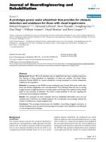
Figure 2.1: Collision Avoidance Scenario
With the above definition, it can be deduced that:
R2 = x f 2 + y f 2
(1)
x f = R cos θ
(2)
y f = R sin θ
(3)
This determines the equations of motion for the flight platform’s position.
And
V = u 2 + v2
dx f
(4)
= u = V cos χ
(5)
= v = V sin χ
dt
du
−v
ɺɺ
xf =
= a
dt
V
(6)
xɺ f =
yɺ f =
ɺɺ
yf =
dt
dy f
dv
u
= a
dt
V
(7)
(8)
which in turn determines the equation of motion for the flight platform’s velocity. As
shown in equation (7) and (8), it is assumed that there is only an applied acceleration
orthogonal to the flight platform’s velocity as aerodynamic forces on flight surfaces
are always orthogonal to the velocity.
12
Design and Analysis of Collision Avoidance Algorithm
A practical approach to the algorithm will be to base it on variables that will be
measurable from the flight platform. One such variable is the range, R, between the
obstacle and the flight platform. This can be easily obtained by having range sensors
onboard the flight platform.
Another one such variable is the flight platform bearing, χ, where the angles are
measured positive anticlockwise from the X axis.
Thus, in order to obtain rates such as Rɺ and θɺ in terms of measurable variables
range R, and flight platform heading χ, take equation (1):
R2 = x f 2 + y f 2
differentiate with respect to time, t:
2R
dR
= 2 x f xɺ f + 2 y f yɺ f
dt
y
dR x f
=
xɺ f + f yɺ f
dt
R
R
dR
= V cos θ cos χ + V sin θ sin χ
dt
⇓
dR
= Rɺ = V cos ( χ − θ )
dt
(9)
13
Design and Analysis of Collision Avoidance Algorithm
Also:
tan θ =
yf
xf
differentiating with respect to time, t:
sec2 θ
yɺ f x f − xɺ f y f
dθ
=
dt
x2 f
sec2 θ
yɺ f x f − xɺ f y f
dθ
=
dt
x2 f
=
=
x f V sin χ − y f V cos χ
( R cos θ )
2
x f V sin χ − y f V cos χ
R2
sec 2 θ
⇓
yf
dθ
V xf
=
sin χ − cos χ
dt
R R
R
dθ
V
= θɺ =
sin( χ − θ )
dt
R
(10)
Also, to obtain rates Vɺ and χɺ in relation to the applied acceleration a, take equation
(4):
V = u 2 + v2
V 2 = u 2 + v2
differentiate with respect to time, t:
2V
dV
du
dv
= 2u
+ 2v
dt
dt
dt
14
Design and Analysis of Collision Avoidance Algorithm
Substituting in equations (5) – (8)
V
dV
−v
u
= V cos χ . a + V sin χ . a
dt
V
V
dV
−V sin χ
V cos χ
= cos χ . a
+ sin χ . a
dt
V
V
= a ( − cos χ sin χ + cos χ sin χ )
⇓
dV
= Vɺ = 0
dt
(11)
Also
cos χ
V = V
ɶ
sin χ
&
− sin χ
a = a
ɶ
cos χ
Thus,
Vɺ = a
ɶ ɶ
⇓
dV
dt
cos χ
− sin χ d χ
− sin χ
= a
+ V
sin χ
cos χ dt
cos χ
⇓
− sin χ d χ
− sin χ
V
= a
cos χ dt
cos χ
Substituting in equation (11)
V
dχ
=a
dt
dχ
a
= χɺ =
dt
V
(12)
15