CONVERSION OF LEVULINIC ACID TO GAMMA VALEROLACTONE USING p CYMENE RU(II) n HETEROCYCLIC CARBENE COMPLEXES
Bạn đang xem bản rút gọn của tài liệu. Xem và tải ngay bản đầy đủ của tài liệu tại đây (4.06 MB, 121 trang )
CONVERSION OF LEVULINIC ACID TO GAMMAVALEROLACTONE USING p-CYMENE RUTHENIUM(II) NHETEROCYCLIC CARBENE COMPLEXES
TAY BOON YING
(B.Sc. (Hons.), NUS)
A THESIS SUBMITTED
FOR THE DEGREE OF MASTER OF SCIENCE
DEPARTMENT OF CHEMISTRY
NATIONAL UNIVERSITY OF SINGAPORE
2013
DECLARATION
I hereby declare that this thesis is my original work and it has been written by me in its
entirety, under the supervision of Associate Professor Huynh Han Vinh, Chemistry
Department, National University of Singapore and Dr. Ludger Paul Stubbs, Polymer
Engineering and Catalysis, Institute of Chemical and Engineering Sciences, between 8
August 2011 and 16 September 2013.
I have duly acknowledged all the sources of information which have been used in the
thesis.
This thesis has also not been submitted for any degree in any university previously.
TAY BOON YING
Name
16 September 2013
Signature
Date
ACKNOWLEDGEMENT
I would like to take this opportunity to express my gratitude and heartfelt appreciation to
the following people for their help, encouragement and support throughout this research
journey:
Associate Professor Huynh Han Vinh (my supervisor at the National University of
Singapore, NUS) for his insightful guidance, support, encouragement and friendship. I
would also like to thank him for his patience and understanding as well as the time spent
in the evenings after group meeting for discussions.
Associate Professor Leong Weng Kee (Honours Year Supervisor) for encouraging me to
continue with my graduate studies.
Dr. Ludger Paul Stubbs (my supervisor at the Institute of Chemical and Engineering
Sciences, ICES) for giving me the autonomy in this project. I would also like to thank him
for his care, understanding, friendship and support.
Dr. Phua Pim Huat (my mentor at the ICES) for sharing with me his knowledge on
nanoparticles, and for assistance with HPLC analysis.
Dr. Wang Cun (my mentor at the ICES) for sharing and guiding me in various aspects in
synthesis and crystallographic analysis. I would also like to thank him for his assistance
in solving the crystal structures obtained in this project and the discussions we had in the
lab.
Dr. Martin van Meurs for the discussion on reaction kinetics and catalysis.
I
Members of the Central Analytical Laboratory, ICES for their assistance and support:
Ms. Seo Pei Nee for her guidance and assistance on the operation of TEM, Ms. Chia
Sze Chen for X-ray crystallographic analysis, Mr. Ng Fu Song for elemental analysis, Mr.
Jeffrey Ng and Ms. Doris Tan for the MS analysis, Ms. Ong Lili for NMR analysis, Mr.
Lee Koon Yong and Mr. Lee Ah Teck for the gas line support.
My company, ICES, for the encouragement and financial support for this project.
My examiners for taking their precious time in reviewing my thesis.
Last but not least, I would like to express my heartfelt appreciation to my family, close
friends and colleagues of the Polymer Engineering and Catalysis group, Vinh’s group
members for their constant understanding, encouragement, patience, support and
advice.
II
TABLE OF CONTENTS
ACKNOWLEDGEMENT ................................................................................................... I
TABLE OF CONTENTS ................................................................................................. III
SUMMARY .................................................................................................................... VI
COMPOUNDS NUMBERING SCHEME ...................................................................... VIII
LISTS OF TABLES ........................................................................................................ X
LIST OF FIGURES ....................................................................................................... XII
LISTS OF SCHEMES .................................................................................................. XVI
LIST OF CHART ....................................................................................................... XVIII
LIST OF ABBREVATIONS .......................................................................................... XIX
1. INTRODUCTION ........................................................................................................ 1
1.1.
Global energy demands and environmental issues ........................................... 1
1.2.
Biomass as an alternative energy source .......................................................... 2
1.3.
Levulinic Acid and γ-valerolactone .................................................................... 3
1.4.
Conversion of LA to GVL................................................................................... 5
1.4.1.
Catalytic homogeneous hydrogenation using molecular H2 ........................ 7
1.4.2.
Catalytic heterogeneous hydrogenation using molecular H2 ....................... 7
1.4.3.
Using formic acid as the alternative hydrogen source ................................ 8
1.4.4.
Water as the solvating media ................................................................... 10
1.4.5.
Metal nanoparticles as catalysts............................................................... 10
III
1.5.
N-heterocyclic carbenes .................................................................................. 11
1.5.1.
Definition and properties .......................................................................... 11
1.5.2.
Preparation of NHC complexes and characterisation ............................... 14
1.6.
Objective of the study ...................................................................................... 17
2. RESULTS AND DISCUSSIONS ............................................................................... 19
2.1.
Synthesis and characterization of p-cymene Ru(II) NHC complexes ............... 19
2.1.1.
p-cymene Ru(II) NHC complexes bearing monodentate NHC ligands ...... 19
2.1.2.
p-cymene Ru(II) NHC complexes bearing bidentate NHC ligands ............ 22
2.2.
Catalytic hydrogenation of LA to GVL using molecular H2 as the hydrogen
source (Route 1) ............................................................................................. 29
2.2.1.
Optimisation of reaction conditions ........................................................... 29
2.2.2.
Catalyst screening.................................................................................... 32
2.2.3.
Kinetics .................................................................................................... 35
2.3.
Catalytic hydrogenation of LA to GVL using FA as the hydrogen source (Route
2) .................................................................................................................... 42
2.3.1.
Optimisation of reaction conditions ........................................................... 42
2.3.2.
Catalyst screening.................................................................................... 45
2.4.
Appearance of the reaction mixture for the two different routes ....................... 47
2.5.
Methods to probe the catalytic nature.............................................................. 48
2.5.1.
TEM Studies ............................................................................................ 48
2.5.2.
Mercury poisoning test ............................................................................. 53
2.5.3.
UV Measurement ..................................................................................... 55
IV
2.6.
Effect of additive on Route 1 ........................................................................... 57
2.7.
Catalyst recycling experiments ........................................................................ 60
2.8.
Effects of water and FA on nanoparticle formation .......................................... 62
2.8.1.
Hydrogenation of cyclohexanone to cyclohexanol .................................... 65
3. CONCLUDING REMARKS ....................................................................................... 67
4. FUTURE WORK ....................................................................................................... 69
5. EXPERIMENTAL SECTION ..................................................................................... 72
5.1.
Methods and materials .................................................................................... 72
5.2.
Analysis .......................................................................................................... 72
5.3.
Catalysis ......................................................................................................... 73
5.3.1.
General procedure of catalytic hydrogenation of LA to GVL using molecular
H2 (Route 1)............................................................................................. 73
5.3.2.
General procedure of catalytic hydrogenation of LA to GVL using FA as the
H2 source (Route 2) ................................................................................. 74
5.4.
Synthesis of Ligand Salt Precursors ................................................................ 74
5.5.
Synthesis of p-cymene Ru NHC Complexes ................................................... 76
6. REFERENCES ......................................................................................................... 82
7. APPENDIX ............................................................................................................... 88
V
SUMMARY
Fossil fuel has always been the main source of energy since the eighteenth century.
However due to its depletion and related environmental concerns, there has been a shift
towards renewable sources of energy. Biomass is a suitable alternative as it is the only
renewable source of organic carbon that is essential for the production of liquid
hydrocarbon fuels to chemicals. One of the top twelve useful platform chemicals that can
be derived from biomass is levulinic acid (LA) that can be converted to gammavalerolactone (GVL) via hydrogenation.
This thesis describes the synthesis and characterisation of three p-cymene Ru(II)
complexes bearing monodentate N-heterocyclic carbene (NHC) ligand and three pcymene Ru(II) complexes bearing bidentate NHC-NHC/NHC-py ligand and their catalytic
activity on the catalytic hydrogenation of LA to GVL. [RuCl2(η6-p-cymene)(iPr2-bimy)] (2),
[RuCl2(η6-p-cymene)(Bn2-bimy)] (3) and [RuCl(η6-p-cymene)(κ2C,C-diNHCme)][PF6] (4)
were characterised by X-ray diffraction analyses. Two hydrogen sources, molecular
hydrogen (Route 1) and formic acid (FA, Route 2) were used in the catalytic
hydrogenation of LA to GVL.
In Route 1, we found that the catalysis proceeded in a heterogeneous fashion where the
ruthenium complexes act as a precursor to catalytically active ruthenium nanoparticles
(RuNPs) rather than a soluble metal catalyst. Under reducing H2 atmosphere, the
catalyst precursor will rapidly be converted to RuNPs. At the end of the reaction, metallic
plating was found on the reaction liner and magnetic stir bar. RuNPs were seen during
transmission electron microscopy (TEM) analysis. Mercury poisoning experiments also
showed positive results where there was a significant drop in the GVL yield. The
VI
disappearance of absorption maxima with time in the UV spectroscopic study indicated
that the catalyst precursor was being converted to RuNPs.
In the solvent selection study, we discovered that water is the best solvent for our
optimised reaction conditions. Water is also the best solvent in the catalytic
hydrogenation of cyclohexanone to cyclohexanol using our p-cymene Ru(II) NHC
complexes as it aids in RuNPs dispersion. In the effect of additive study on Route 1, we
discovered that pH has an effect on the stability of the RuNPs. RuNPs tend to aggregate
at low pH. p-cymene Ru(II) complexes bearing monodentate NHC ligands generally
performed better as compared to the complexes bearing bidentate ligands and catalysis
via Route 1 with p-cymene Ru(II) complexes bearing monodentate NHC ligands
proceeded via zero-order kinetics with respect to LA and first-order kinetics with respect
to H2. The best performing catalyst was 2 where almost quantitative yield was achieved
in 120 min.
In Route 2, the catalysis was found to proceed in a homogeneous fashion as FA present
might aid in the formation of a formate-bridged ruthenium dimers that will first catalyse
the decomposition of FA to H2 and CO2 followed by the formation of GVL. RuNPs were
absent for most of the catalysts screened and mercury poisoning experiments showed
no decrease in GVL yield. The absorption spectrum of for the Ru(II) species did not
change throughout the course of the catalysis. With respect to the catalytic performance,
the trend was similar to the catalyst performance in Route 1. p-cymene Ru(II) complexes
bearing monodentate NHC ligands generally performed better as compared to the
complexes bearing bidentate ligands. The best performing catalyst was 2 where 90.7%
GVL was obtained.
VII
COMPOUNDS NUMBERING SCHEME
Ligand Precursor Salts
1,3-Diisopropylimidazolium chloride
1,3-Diisopropylbenzimidazolium
i
( Pr2-imy·HCl)
Salt A
bromide (iPr2-bimy·HBr)
Salt B
1,3-Dibenzylbenzimidazolium
1,1'-Dimethyl-3,3'-methylene-
bromide (Bn2-bimy·HBr)
diimidazolium dibromide
me
(diimy ·2HBr)
Salt C
Salt D
1,1'-Dimethyl-3,3'-ethylene-
3-Methyl-1-(2-picolyl)imidazolium
diimidazolium dibromide
chloride
et
(py-imy·HCl)
(diimy ·2HBr)
Salt E
Salt F
VIII
p-cymene Ruthenium(II) NHC complexes
6
i
6
[RuCl2(η -p-cymene)( Pr2-imy)]
1
i
[RuCl2(η -p-cymene)( Pr2-bimy)]
2
6
6
[RuCl2(η -p-cymene)(Bn2-bimy)]
3
2
me
[RuCl(η -p-cymene)(κ C,C-diNHC )][PF6]
4
6
2
et
6
[RuCl(η -p-cymene)(κ C,C- diNHC )][PF6]
2
[RuCl(η -p-cymene)(κ C,N-Me,pyimy)][PF6]
5
6
IX
LISTS OF TABLES
Table 1. Summary of some physical properties of LA.[11] ................................................. 4
Table 2. Summary of some physical properties of GVL.[9] ............................................... 5
Table 3. Summary of some thermodynamic properties of FA decomposition
pathways.[18c] ................................................................................................................... 9
Table 4. Selected interatomic distances (Å) and angles (). .......................................... 22
Table 5. Ccarbene-Ru and Ru-Cl distances [Å] for 4, 5 and 6. .......................................... 28
Table 6. Catalyst loading optimisation using the reported optimised condition.[a] ........... 30
Table 7. Solvent screening using 0.1 mol% 1................................................................ 30
Table 8. Pressure screening using 0.1 mol% 1 and water as solvent. ........................... 31
Table 9. Pressure screening using 0.1 mol% 1, water as solvent and 12 bar H2. .......... 31
Table 10. Summary of the outcome for catalyst screening[a] ......................................... 33
Table 11. Summary of the rate constant and linearity of [RuCl2(p-cymene)]2 and
complexes bearing monodentate NHC ligands 1 to 3. ................................................... 35
Table 12. Summary of the rate constant and linearity of [RuCl2(p-cymene)]2 and
complexes bearing bidentate NHC ligands 4 to 6. ......................................................... 38
X
Table 13. Summary of the rate of reaction under 1, 6 and 12 bars using 0.1 mol% 1 as
the catalyst at 130 C under 1, 6 and 12 bar H2 for 160 min. ......................................... 40
Table 14. Temperature screening with/without water as solvent. .................................. 43
Table 15. Temperature screening without water as solvent........................................... 44
Table 16. Summary of the outcome for catalyst screening.[a] ........................................ 46
Table 17. Summary of mercury poisoning test for the conversion of LA to GVL via Route
1 and Route 2................................................................................................................ 54
Table 18. Summary of mercury poisoning test for the conversion of LA to GVL via Route
2.[a] ................................................................................................................................ 54
Table 19. Summary of the results obtained from the study of the effect of additives on
Route 1. ........................................................................................................................ 57
Table 20. Summary of the pH of reaction mixtures taken before hydrogenation via Route
1[a]. ................................................................................................................................ 59
Table 21. Summary of the results obtained from various variations in reaction condition.
...................................................................................................................................... 63
Table 22. Summary of the results obtained from hydrogenation of cyclohexanone[a]
using water and THF. .................................................................................................... 66
XI
LIST OF FIGURES
Figure 1. World energy consumption from 1990 to 2035.[1] ............................................. 1
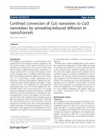
Figure 2. Global CO2 emission from fossil fuels from 1900-2009.[3]................................. 2
Figure 3. Organic components of lignocelluloic biomass and examples of useful
chemical/intermediates that can be obtained from acid catalysed hydrolysis. .................. 3
Figure 4. Derivatives of levulinic acid.[12] ......................................................................... 4
Figure 5. FA produced from acidic hydrolysis of lignocelluosic biomass can be directly
used as the hydrogen source with a suitable catalyst to be decomposed to H2 and CO2
followed by the conversion of LA to GVL. ........................................................................ 8
Figure 6. Examples of Fischer carbene, Schrock carbene and NHC. ........................... 12
Figure 7. Grubbs second generation catalyst................................................................ 12
Figure 8. Common azole rings used to tune the electronics of NHC. ............................ 14
Figure 9. p-cymene Ru(II) NHC complexes with monodentate NHC ligands (1 to 3) and
bidentate NHC ligands (4 to 6) used in the study. .......................................................... 18
Figure 10. Molecular structures of 2 (a) and 3 (b) with thermal ellipsoids drawn at 30%
probability level. Hydrogen atoms are omitted for clarity. ............................................... 21
Figure 11. Molecular structure of 4 with thermal ellipsoids drawn at 30% probability
level. Hydrogen atoms and hexafluorophosphate anion are omitted for clarity. Selected
bond lengths [Å] and angles []: Ru(1)-C(4) 2.041(4), Ru(1)-C(6) 2.047(4), Ru(1)-Cl(1)
XII
2.413(1), Ru(1)-Ct1* 1.739, C(4)-Ru(1)-C(6) 83.3(2), N(2)-C(1)-N(3) 109.9(4), C(4)Ru(1)-Cl(1) 86.3(1), C(6)-Ru(1)-Cl(1) 86.3(1). *Ct1 denotes centroid formed by C(10)C(15). ............................................................................................................................ 28
Figure 12. Reaction profile of catalytic hydrogenation of LA to GVL using 1 from 0 to 160
min. ............................................................................................................................... 32
Figure 13. Plot of LA depletion vs. time for [RuCl2(p-cymene)]2. ................................... 36
Figure 14. Plot of LA depletion vs. time for 1. ............................................................... 36
Figure 15. Plot LA depletion vs. time for 2. ................................................................... 37
Figure 16. Plot of LA depletion vs. time for 3. ............................................................... 37
Figure 17. Plot of LA depletion vs. time for 4. ............................................................... 38
Figure 18. Plot of LA depletion vs. time for 5. ............................................................... 39
Figure 19. Plot of LA depletion vs. time for 6. ............................................................... 39
Figure 20. Plot of reaction rate vs. hydrogen pressure.................................................. 41
Figure 21. Effect of base loading on GVL yield (yield reflected is an average of two
runs). ............................................................................................................................. 44
Figure 22. Plot of GVL formation and LA depletion with time. ....................................... 45
Figure 23. Appearance of reaction mixture after reaction. A. Using molecular H2 (Route
1), colourless solution was obtained with metallic coating on liner wall and magnetic stir
XIII
bar. Reaction condition: 4.31 mmol LA, 0.1 mol% 1, 10 mL water, 12 bar H2, 130 C, 160
min. B. Using FA as the H2 source (Route 2), yellow solution was obtained with clean
liner wall and magnetic stir bar. Reaction condition: 80 mmol LA, 80 mmol FA, 0.075
mol% 1, 3 mol% NaOH, 130 C, 12 h. ........................................................................... 47
Figure 24. TEM images of [RuCl2(p-cymene)]2 using molecular H2 at 30 min (left), 90
min (middle) and 160 min (right). ................................................................................... 49
Figure 25. TEM images of 1 using molecular H2 at 30 min (left), 90 min (middle) and 160
min (right). ..................................................................................................................... 50
Figure 26. TEM images of 2 using molecular H2 at 30 min (left), 90 min (middle) and 160
min (right). ..................................................................................................................... 50
Figure 27. TEM images of 3 using molecular H2 at 30 min (left), 90 min (middle) and 160
min (right). ..................................................................................................................... 50
Figure 28. TEM images of 4 using molecular H2 at 30 min (left), 90 min (middle) and 160
min (right). ..................................................................................................................... 51
Figure 29. TEM images of 5 using molecular H2 at 30 min (left), 90 min (middle) and 160
min (right). ..................................................................................................................... 51
Figure 30. TEM images of 6 using molecular H2 at 30 min (left), 90 min (middle) and 160
min (right). ..................................................................................................................... 51
Figure 31. TEM images of catalytic hydrogenation of LA to GVL using molecular H2 as
the hydrogen source. A. Ru/C 4. B. [RuCl2(PPh3)]. ....................................................... 52
XIV
Figure 32. TEM images of catalytic hydrogenation of LA to GVL using FA as the
hydrogen source. A. Ru/C. B. Complex 4. C. Complex 6. ............................................. 53
Figure 33. UV spectra of 1 at 0.0004M for catalytic hydrogenation of LA to GVL using A.
Route 1 from 0 – 160 min. B. Route 2 from 0 – 24 h. .................................................... 55
Figure 34. Colour changes of 0.004M of reaction mixtures throughout the course of
reaction via A. Route 1; B. Route 2. .............................................................................. 56
Figure 35. TEM images of 1 when different additives were added. ............................... 58
Figure 36. TEM image of 1 after second catalytic run. .................................................. 61
Figure 37. TEM images of RuNPs formed in A. Scenerio 3 and B. Scenerio 4. ............ 63
Figure 38. Structure of formate-bridged ruthenium dimers.[47] ....................................... 64
Figure 39. TEM images obtained for 1 in the conversion of LA to GVL using different
solvents. ........................................................................................................................ 64
XV
LISTS OF SCHEMES
Scheme 1. Reaction pathways of LA to GVL.[17n] ............................................................ 6
Scheme 2. Conversion of LA to GVL using molecular H2 or FA as the hydrogen source.6
Scheme 3. Synthesis scheme of the first stable NHC. .................................................. 13
Scheme 4. Electronic configuration and resonance structures of NHC.[29]..................... 13
Scheme 5. Common synthetic routes towards NHC complexes.................................... 16
Scheme 6. Synthesis of the p-cymene Ru(II) NHC complexes 1 to 3. ........................... 19
Scheme 7. Synthesis of 4. ............................................................................................ 23
Scheme 8. Synthesis of 5. ............................................................................................ 25
Scheme 9. Literature reported procedure for the synthesis of salt F.[34]......................... 25
Scheme 10. Modified procedure for the synthesis of salt F. .......................................... 26
Scheme 11. Synthesis of 6. .......................................................................................... 26
Scheme 12. Reaction scheme of catalytic hydrogenation of LA to GVL via Route 1 with
optimised conditions by Yan et. al..[17m].......................................................................... 29
Scheme 13. Reaction scheme of catalytic hydrogenation of LA to GVL via Route 2 with
optimised conditions by Deng et. al..[11q] ........................................................................ 42
Scheme 14. Hydrogenation of cyclohexanone to cyclohexanol. .................................... 65
XVI
Scheme 15. Proposed ways to convert biomass-derived LA to GVL using our optimised
routes. ........................................................................................................................... 69
Scheme 16. Hydrogenation of acetanilide to N-cyclohexylacetamide using 1. .............. 70
XVII
LIST OF CHART
Chart 1. Methods of synthesizing MNPs and methods of stabilizing MNPs. .................. 11
XVIII
LIST OF ABBREVATIONS
AcOH
Acetic Acid
API
Atmospheric Pressure Ionisation
Ar
aryl
bimy
benzimidazolin-2-ylidene
Bn
benzyl
bpy
bipyridine
Calcd.
calculated
CCD
Charged Coupled Device
CO2
carbon dioxide
Ct
Centroid
d
doublet
DCM
Dichloromethane
dd
doublet of doublet
DMSO
dimethyl sulfoxide
EA
Elemental Analysis
eq
equivalent
ESI-MS
Electrospray Ionization Mass Spectrometry
et
ethyl bridge
et. al.
and others (Latin et alii)
e.g.
for example (Latin exempli gratia)
FA
Formic Acid
GVL
γ-valerolactone
XIX
h
hour
HPLC
High Performance Liquid Chromatography
Hz
hertz
I
Inductive effect
imid
imidazole
imy
imidazolin-2-ylidene
i
Pr
isopropyl
J
coupling constant
LA
Levulinic Acid
LC
liquid chromatography
M
Mesomeric effect
m
multiplet
m/z
mass to charge ratio
Me
methyl
me
methyl bridge
MeOH
Methanol
min
minutes
mL
milliliter
MNPs
Metal Nanoparticles
MS
Mass Spectrometry
NHC
N-Heterocyclic Carbene
nm
nanometers
NMR
Nuclear Magnetic Resonance
NREL
National Renewable Energy Laboratory
XX
Ph
phenyl
py
pyridine
RuNPs
Ruthenium Nanoparticles
s
singlet
sept
septet
TEM
Transmission Electron Microscopy
THF
Tetrahydrofuran
UV-Vis
Ultraviolet-Visible
vs.
versus
δ
NMR chemical shift in ppm
λmax
absorption maxima
μL
microliter
XXI
Conversion of LA to GVL using p-cymene Ru(II) NHC Complexes
1. INTRODUCTION
1.1.
Global energy demands and environmental issues
Since the eighteenth century, fossil fuel has been the main energy source for human and
economical developments. With the increasing human population and technological
advances, the energy needed to meet the economic and social demand increased
(Figure 1) in order to sustain human well-being and raise the standard of living.
World Energy comsumption from 1990-2035
History
2013
Quadrillion Btu
800
Projection
600
400
200
0
1990
2000
2010
2020
2030
Year
Liquids
Natural gas
Coal
World
Figure 1. World energy consumption from 1990 to 2035.
[1]
Fossil fuels have been gradually declining due to increasing usage. Environmental
problems like high carbon dioxide (CO2) emission (Figure 2) led to increasing drastic
climatic changes. CO2 emission has led to global warming and increase in average
global temperature of 0.8 C since 1880.[2] Hence, there is a pressing need in search of
alternative energy source that is sustainable and environmentally benign.
Page 1
Conversion of LA to GVL using p-cymene Ru(II) NHC Complexes
Global CO2 emission from fossil fuels from 19002009
35000
CO2 emission
(tetragrams CO2)
30000
25000
20000
15000
10000
5000
0
1900
1920
1940
1960
1980
2000
Year
[3]
Figure 2. Global CO2 emission from fossil fuels from 1900-2009.
1.2.
Biomass as an alternative energy source
Biomass is biological material that is derived from living, or recently living organisms. In
the context of biomass for energy this is often used to mean plant based material, but
biomass can equally apply to both animal and vegetable derived material.[4] Biomass is a
suitable alternative as it is the only renewable source of organic carbon, which is
essential for the production of liquid hydrocarbon fuels to chemicals. [5] In the Kyoto
protocol, together with the vision to reduce crude oil dependence, researchers’ attention
has been directed to use biomass as a source of energy and, more specifically, for
transportation fuels.[5-8]
The organic components present in lignocellulosic biomass consist of cellulose,
hemicellulose and lignin.[9] Upon acid catalysed hydrolysis, it can be broken down into
useful chemicals and intermediates (Figure 3).
Page 2