Design of CMOS receivers and building blocks for ultra wideband radio
Bạn đang xem bản rút gọn của tài liệu. Xem và tải ngay bản đầy đủ của tài liệu tại đây (1.33 MB, 114 trang )
DESIGN OF CMOS RECEIVERS AND BUILDING
BLOCKS FOR ULTRA-WIDEBAND RADIO
TONG
YAN
(B. Eng. , Zhejiang University)
A THESIS SUBMITTED
FOR THE DEGREE OF MASTER OF ENGINEERING
DEPARTMENT OF ELECTRICAL AND COMPUTER
ENGINEERING
NATIONAL UNIVERSITY OF SINGAPORE
2006
i
Name: TONG YAN
Degree: Master of Engineering
Department: Electrical and Computer Engineering, NUS
Thesis Title: Design of CMOS Receivers and Building Blocks for Ultra-Wideband
Radio
Abstract
In this thesis, receiver systems and CMOS integrated circuits design for
Ultra-Wideband (UWB) communication are proposed.
Several building blocks for the receivers are designed in a 0.18-µm CMOS
technology. Cross-coupled transistors with source followers are used to implement
the multiplier. Inductor peaking technique is employed to enhance multiplier
bandwidth with more than 7 GHz bandwidth. A continuous-time negative
feedback loop is employed in the VGA to suppress DC-offset by 15 dB while
obtaining 45 dB dynamic range. The integrator employs Gm − C − OTA structure
to obtain a unit gain frequency of around 1 GHz and low -3 dB bandwidth of less
than 1MHz.
Two UWB receiver architectures are proposed and implemented using the
proposed building blocks. The coherent receiver achieves simulated transmission
rate of 100 MHz and sensitivity of -80 MHz, and the non-coherent receiver
achieves measured transmission rate of 50 MHz and sensitivity of -65 dBm.
Keywords: ultra-wideband, receiver, DC-offset, multiplier, variable gain amplifier,
integrator.
ii
Acknowledgements
I would like to express my deepest gratitude to my supervisor, Dr. Zheng
Yuanjin, for the opportunity to work on an interesting research topic and his
encouragement, guidance and many invaluable ideas during the research. I am
also extremely grateful to my associate supervisor, Assoc. Prof Xu Yong Ping, for
his guidance and patience. His invaluable comments has made breakthrough to the
whole research project.
I would also like to take this opportunity to thank the Institute of
Microelectronics for the award of a research scholarship under Joint
Microelectronics Laboratory with National University of Singapore and Integrated
Circuits and System Laboratory for providing excellent facilities, without which
the present work would not have been possible. Thanks also go to the National
University of Singapore for giving me the opportunity to pursue postgraduate
study.
I am grateful to Mr. Wong Sheng Jau, and Mr. Oh Boon Hwee for their
numerous extended discussions, clear thoughts and generous assistance provided
throughout the project.
iii
I would like to thank my friends Cao Rui, Zhou Qiaoer, Yan Jiangnan and
Yang Liu, Wei Xiaoqian and Cao Mingzheng who are working together with me
in IME. The relaxed and inspiring team atmosphere with them is very helpful to
the completion of this work.
I want to express my gratitude to my colleagues Zhou Lei, Chen Jianzhong,
Pu Yu, Yu Rui, Yu Jianghong, Gu Jun, Hu Yingpin, He Ying, Wei Ying, Wu Hong
Lei and M. Umashankar at the NUS Signal Processing and VLSI Design
laboratory for creating a relaxed and pleasant working atmosphere.
Finally, I am deeply indebted to my family for their unconditional love,
encouragement and support. They have been extremely important not only in
making me who I am, but also in helping me through the highs and lows that have
accompanied my academic endeavor.
iv
Table of Contents
Abstract ............................................................................................................... ii
Acknowledgements............................................................................................. iii
Table of Contents................................................................................................. v
Summary .......................................................................................................... viii
List of Tables ....................................................................................................... x
List of Figures .................................................................................................... xi
List of Symbols and Abbreviations ................................................................... xiv
Chapter 1 Introduction ......................................................................................... 1
1.1 Background and Motivation .................................................................... 1
1.1.1 Overview of Ultra-Wideband System............................................. 1
1.1.2 Motivation..................................................................................... 4
1.2 Organization of the Thesis....................................................................... 5
Chapter 2 UWB Receiver Architectures ............................................................... 7
2.1 Overview of Receiver Architectures ........................................................ 7
2.1.1 An Overview of Direct Conversion Receiver Architecture ............. 7
2.2.2 DS-UWB Receiver Architectures in the Literature........................11
2.2 Proposed UWB Modulation Schemes and Receiver Architectures ......... 14
2.2.1 Antipodal Modulation and Coherent Receiver Architecture.......... 14
2.2.2
On-Off
Keying
Modulation
and
Non-Coherent
Receiver
Architecture ......................................................................................... 21
Chapter 3 UWB Receiver Building Blocks Design ............................................ 25
3.1 Multiplier .............................................................................................. 26
v
3.1.1 CMOS Transconductance Analog Multiplier................................ 26
3.1.2 Proposed Multiplier for Ultra-Wideband Receiver ....................... 33
3.2 Variable Gain Amplifier ........................................................................ 39
3.2.1 General Consideration ................................................................. 39
3.2.2 Existing Gain Varying Techniques ............................................... 40
3.2.3 DC-Offset Cancellation Techniques ............................................. 42
3.2.4 Proposed VGA Circuits with DC-offset Suppression Loop and
Simulated Performance ........................................................................ 45
3.3 Integrator .............................................................................................. 51
3.3.1 Integrators in the Literature.......................................................... 51
3.3.2 Proposed Integrator Structure ...................................................... 55
3.3.3 Circuits implementation and Performance.................................... 61
3.4 Comparator ........................................................................................... 66
3.5 A Brief Overview of Other Receiver Building Blocks............................ 68
3.5.1 Low Noise Amplifier ................................................................... 68
3.5.2 Pulse Generator ........................................................................... 69
3.5.3 Demodulation Drive Amplifier .................................................... 70
3.5.4 Low Pass Filter............................................................................ 71
Chapter 4 UWB Receiver Integration and Performance ..................................... 72
4.1 Coherent Receiver Implementation and Performance ............................ 72
4.1.1 Coherent Receiver Integration ..................................................... 72
4.1.2 Simulated Performance of the Coherent Receiver ........................ 74
4.2 Non-Coherent Receiver Implementation and Performance .................... 76
4.2.1 Non-Coherent Receiver Integration ............................................. 76
4.2.2 Measured Performance of the Non-Coherent Receiver................. 76
4.3 Layout Considerations........................................................................... 79
Chapter 5 Conclusions and Future Directions..................................................... 81
5.1 Conclusions........................................................................................... 81
5.2 Future Directions................................................................................... 82
Bibliography...................................................................................................... 83
vi
Appendix A Layout of the Coherent Receiver Chip............................................ 94
Appendix B Die Micrograph of the Non-Coherent Receiver chip....................... 95
Appendix C Publications ................................................................................... 96
vii
Summary
This thesis focuses on receiver systems and CMOS integrated circuits design
for Ultra-Wideband (UWB) communication.
Two modulation schemes for UWB communication and corresponding
receiver architectures are proposed. They are the correlator based BPSK coherent
receiver capable of high transmission rate and good sensitivity, and the pulse OOK
non-coherent receiver with low complexity due to elimination of synchronization.
Several building blocks including multiplier, VGA, integrator and comparator
for UWB receiver are proposed and implemented in a 0.18-µm CMOS technology.
The multiplier has achieved a -3 dB bandwidth larger than 7 GHz and maximum
gain larger than 13 dB. With a DC-offset suppression feedback loop, the VGA has
more than 15 dB offset suppression, 45 dB gain variation range, and 178 MHz -3
dB bandwidth. The integrator employs Gm − C − OTA structure to obtain unit
gain frequency of around 1 GHz and low -3 dB bandwidth of less than 1 MHz. It
can perform the integration on narrow pulses within 1ns and hold for 10 ns with
less than 3% discharge error. A comparator with 90 mV hysteresis and 400 ps
propagational delay is designed.
viii
Based on the proposed receiver architectures and building blocks as well as a
low noise amplifier, a demodulation drive amplifier, a lowpass filter and a local
pulse generator designed by group members, a coherent and a non-coherent UWB
receivers are implemented. The coherent receiver achieves 100 MHz data
transmission rate, 80 dB gain and -80 dBm sensitivity in simulation. The
non-coherent receiver has a measured transmission rate up to 50 MHz, 70 dB gain
and -65 dBm sensitivity.
ix
List of Tables
Table 1: Summary of Simulated Coherent Receiver Performance................ 75
Table 2: Summary of Non-Coherent Receiver Performance......................... 79
x
List of Figures
Fig. 1. 1: FCC Spectral Mask for UWB Communication Systems ................. 2
Fig. 1. 2: Typical UWB monocycle pulse signal. ........................................... 4
Fig. 2.1: Direct Conversion Receiver Architecture………………………...
8
Fig. 2.2: Generation of DC-offsets in Direct Conversion Receiver………... 10
Fig. 2.3: A simple DS-UWB receiver architecture…………………………. 11
Fig. 2.4: DS-UWB receiver architecture employing correlators and RAKE. 12
Fig. 2.5: Autocorrelation DS-UWB receiver architecture………………….. 13
Fig. 2.6: DS-UWB receiver architecture employing matched filter………... 14
Fig. 2.7: Antipodal (BPSK) Modulation for DS-UWB…………………….. 15
Fig. 2.8: Structure of an analog UWB correlator…………………………... 15
Fig. 2.9: Output SNR degradation (dB) when the timing error becomes
larger……………………………………………………………………17
Fig. 2.10: The relation of the correlation function and the correlation time.. 18
Fig. 2.11: Sinusoidal template overlapped with the Gaussian impulse…….. 19
Fig. 2.12: System architecture of coherent UWB receiver for BPSK
modulation……………………………………………………………...19
Fig. 2.13: Non-coherent transceiver system with pulse OOK modulation… 22
Fig. 2.14: Modulation and Demodulation: (a) Binary modulation signal (b)
UWB pulse train (c) Modulated signal (d) Squared signal (e) Lowpass
filtered signal…………………………………………………………... 22
xi
Fig. 3.1: Principle of transconductance multiplier........................................ 27
Fig. 3.2: Four-quadrant multiplier architecture using single-quadrant
multipliers. .......................................................................................... 27
Fig. 3.3: Four-quadrant multiplier architecture using square-law devices..... 28
Fig. 3.4: Type I transconductance multiplier topology. ................................ 30
Fig. 3.5: Type II transconductance multiplier topology. ............................... 30
Fig. 3.6: Type III transconductance multiplier topology. .............................. 31
Fig. 3.7: Proposed multiplier for UWB receiver. ......................................... 33
Fig. 3.8: Bandwidth and gain of the multiplier from RF input to output....... 36
Fig. 3.9: DC transfer characteristic of the multiplier from RF input to output.
............................................................................................................ 36
Fig. 3.10: Bandwidth and gain of the multiplier from LO input to output. ... 37
Fig. 3.11: DC transfer characteristic of the multiplier from LO input to output.
............................................................................................................ 37
Fig. 3.12: Transient simulation of the multiplier. ......................................... 38
Fig. 3.13: Measured multiplier performance................................................ 38
Fig. 3.14: Gain control by vary loading or bias current. ............................... 41
Fig. 3.15: AC-coupling to block DC-offset. ................................................. 43
Fig. 3.16: DC-offset subtraction technique. ................................................. 43
Fig. 3.17: Analog feedback technique: (a) Conceptual diagram. (b)
Frequency response. ............................................................................ 45
Fig. 3.18: Block Diagram of the VGA. ........................................................ 46
Fig. 3.19: Schematic of VGA core circuits. ................................................. 46
Fig. 3.20: VGA core circuits with DC-offset suppression loop. ................... 48
Fig. 3.21: Frequency response of the VGA.................................................. 50
Fig. 3.22: Frequency response of an integrator. (a) ideal case. (b) practical
implementation.................................................................................... 52
Fig. 3.23: Five common integrator structures. ............................................. 53
Fig. 3.24: Two types of capacitor connection............................................... 55
xii
Fig. 3.25: The chosen integrator structure: Gm − C − OTA structure. .......... 58
Fig. 3.26: Equivalent model of the Gm − C − OTA integrator structure....... 59
Fig. 3.27: Proposed integrator structure with feedforward path.................... 61
Fig. 3.28: The schematic of transconductor used in the integrator................ 62
Fig. 3.29: The schematic of OTA used in the integrator. .............................. 63
Fig. 3.30: Frequency response of the integrator. .......................................... 65
Fig. 3.31: Transient Simulation of the integrator.......................................... 65
Fig. 3.32: The measured integrator response to a pulse input. ...................... 66
Fig. 3.33: Schematic of the comparator. ...................................................... 67
Fig. 3.34: The hysteresis characteristic of the comparator. ........................... 67
Fig. 3.35: Schematic of the UWB LNA. ...................................................... 69
Fig. 3.36: Schematic of the differential pulse generator without buffers....... 69
Fig. 3.37: Schematic of the demodulation drive amplifier............................ 70
Fig. 3.38: Schematic of the low pass filter. .................................................. 71
Fig. 4.1: The implemented coherent UWB receiver. .................................... 73
Fig. 4.2: Timing of clocks for pulse generator and integrator. ...................... 73
Fig. 4.3: Transient simulation results of the coherent receiver...................... 74
Fig. 4.4: The implemented coherent UWB receiver. .................................... 76
Fig. 4.5: Measured real time waveforms of data patterns. (Above: transmitted
data pattern, Middle: modulated pulse signal, Below: demodulated and
recovered pattern)................................................................................ 78
xiii
List of Symbols and Abbreviations
Symbols
v1 (t )
Input of multiplier
v2 (t )
Input of multiplier
Id
Bias current of MOSFET
X, Y
Bias of multiplier input
x, y
Small signal at multiplier input
Vgs
Gate-source voltage of MOSFET
VT
Threshold voltage of MOSFET
Vds
Drain-source voltage of MOSFET
K
Transconductance parameter of MOSFET
µ0
Mobility of MOSFET
Cox
Unit gate capacitance of MOSFET
W
Width of MOSFET
L
Length of MOSFET
Io
Output current
xiv
Vout
Output voltage
Z out
Output impedance
VCtrl
Control voltage
Av
Voltage gain
Gs
Transconductance of circuits
Rd
Load impedance
gm
Transconductance of MOSFET
ω− sdB _ VGA
Bandwidth of the VGA
RL
Load resistor
ω− sdB _ FB
Bandwidth of the feedback loop
g ma , g mb
Transconductance of MOSFETs in VGA
Q
Quality factor of low pass filter
ωT
Unit gain frequency of the VGA core
ADC
DC gain of amplifier
ω0
-3dB bandwidth of amplifier
ωu
Unit gain frequency of the integrator
ω−3dB
-3dB band width of amplifier
AGm
DC gain of transconductor
Gm _ Gm
Transconductance of transconductor
Ro _ Gm
Output resistance of transconductor
Gm _ OTA
Transconductance of OTA
AOTA
DC gain of OTA
xv
C2 , C1
Equivalent miller capacitors in integrator
C p _ Gm
Parasitic capacitance of transconductor
C p _ OTA
Parasitic capacitance of OTA
C gm
Equivalent capacitor in transconductor
COTA
Equivalent capacitor in integrator
CCM
Capacitor in common mode feedback loop
RCM
Resistor in common mode feedback loop
Abbreviations
ADS
Advanced Design System
AC
Alternating Current
BER
Bit Error Rate
BPSK
Bi-Phase Shift Keying
CDMA
Code-Division Multiple Access
CMOS
Complementary Metal-oxide semiconductor
COB
Chip-On-Board
CSM
Chartered Semiconductor Manufacturing
DA
Driver Amplifier
DAC
Digital-to-Analog Converter
DC
Direct Current
xvi
DCR
Direct Conversion Receiver
DDA
Demodulation Driving Amplifier
DS-UWB
Direct-Sequence UWB
DSP
Digital Signal Processing
ESD
Electrostatic Discharge
GSG
Ground Signal Ground
FCC
Federal Communication Committee
IF
Intermediate Frequency
I/Q
In-phase/Quadrature
LNA
Low Noise Amplifier
LO
Local Oscillator
LPF
Lowpass Filter
MOS
Metallic Oxide Semiconductor
MOSFET
Metallic Oxide Semiconductor Field Effect
Transistor
MAC
Media Access Control
NMOS
N-type MOS
OOK
On-Off Keying
OTA
Operational Transconductance Amplifier
PG
Pulse Generator
PLL
Phase Locked Loop
PPM
Pulse Position Modulation
PSRR
Power Supply Rejection Ratio
xvii
RAKE
RAKE receiver
RF
Radio Frequency
RX
Receiver
SAW
Surface Acoustic Wave device
SFDR
Spurious-Free Dynamic Range
SNR
Signal to Noise Ratio
SRD
Step Recovery Diodes
THD
Total Harmonic Distortion
UWB
Ultra-Wide Band
VGA
Variable Gain Amplifier
WPAN
Wireless Personal Area Network
xviii
Chapter 1
Introduction
1.1 Background and Motivation
1.1.1 Overview of Ultra-Wideband System
Ultra wideband (UWB) systems are a new wireless technology capable of
transmitting data over a wide frequency spectrum with very low power and high
data rates. Among the possible applications, UWB technology may be used for
high speed data communication systems, vehicular and ground penetrating radars,
and imaging systems. One of its most promising application areas is Wireless
Personal Area Network (WPAN), in which UWB technology is envisioned to
replace almost every cable at home or in an office with a wireless connection that
features hundreds of megabits of data per second [1].
Although the UWB standard for high data rate communication (IEEE
802.15.3a [2]) has not been completely defined, most of the proposed applications
are allowed to transmit in a band between 3.1 – 10.6 GHz. The federal
1
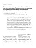
Communication Committee (FCC) has defined the spectral mask for UWB indoor
communication systems, as shown in Fig.1.1. According to FCC’s regulation [3],
UWB transmission is defined as the occupied fraction bandwidth > 20 % or larger
than 500 MHz of absolute bandwidth.
The benefit of UWB can be explained by Shannon’s channel capacity formula
as follow:
Capacity = BW ⋅ log 2 (1 + SNR )
(1.1)
It shows that the capacity increases with the bandwidth linearly, but with signal
power only logarithmically. Thus the UWB systems operating with very low
signal power level can offer much more capacity compared to conventional
narrowband systems.
Fig. 1.1: FCC Spectral Mask for UWB Communication Systems [4].
2
There are two main categories of UWB signaling schemes: Multi-band
Orthogonal Frequency Division Multiplexing (MB-OFDM) [4] based scheme and
Direct-Sequence UWB (DS-UWB) [5] [6] [7] based scheme. The former divides
the whole UWB spectrum into sub-bands with bandwidth of several hundred of
Megahertz, and in each band a conventional carrier based approach is used. The
latter is a carrier-less impulse radio based system in nature, in which either very
narrow impulse signals occupying the whole UWB frequency band (3.1 – 10.6
GHz) can be used, or alternatively several types of impulse signals with different
widths can be used, each occupying a sub-band of the whole UWB spectrum [2].
In this thesis, only impulse radio type UWB (DS-UWB) communication
system is discussed.
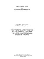
The typical UWB impulse signal is a Gaussian monocycle pulse, which is the
second order derivative of Gaussian function as shown in Fig.1.2.
The Gaussian monocycle pulse signal can be expressed mathematically as [8]:
2
2
t
t
PG ( t ) = AG 1 − − 0.35 exp −0.5 − 0.35
σ
σ
(1.2),
where σ is a coefficient related to the pulse’s width, and AG is a amplitude
scaling factor.
3
Fig. 1. 2: Typical UWB monocycle pulse signal.
1.1.2 Motivation
Implementation of low cost UWB transceiver integrated circuits is a key
success factor for UWB communication systems to be widely adopted. The UWB
receiver chip design is particularly challenging in that it must provide sensitivity
lower than -80 dBm and consume low power to enable longer battery life. The
impulse radio type UWB receiver is quite different from conventional carrier
based wireless receivers. Building blocks which are common in carrier based
receiver system, such as local oscillators and channel select bandpass filters, are
not present in an impulse radio type UWB (DS-UWB) receiver, and almost all of
conventional receiver architectures can not be directly applied to DS-UWB
receivers. As a result, innovations on novel system architecture as well as new
circuits techniques are needed.
In this thesis various key building blocks of impulse radio type UWB wireless
4
receivers such as multiplier, integrator, VGA and comparator are investigated and
two UWB receiver systems are built in 0.18 µm CMOS technology based on the
proposed building blocks and some other available circuit blocks. The two
receivers achieve transmission rates of 100 Mbps and 50 Mbps respectively, and
sensitivity of -85 dBm and -65 dBm respectively. The goal is to solve several
critical problems in DS-UWB receiver design such as correlator design and
DC-offset suppression, and to use simulation and experimental results to verify
the feasibility of integrated UWB receiver solution in low cost CMOS technology.
1.2 Organization of the Thesis
In chapter 2, conventional receiver architectures are briefly reviewed. The
modulation schemes for UWB impulse radio such as Pulse Position Modulation
(PPM), pulse On-Off Keying (OOK) Modulation and Bi-Phase Shift Keying
(BPSK) Modulation are discussed. Based on the adopted BPSK and Pulse OOK
modulation schemes, the correlator based coherent UWB receiver architecture and
the self-synchronized non-coherent UWB receiver architecture are proposed.
Chapter 3 concentrates on design of UWB receiver building blocks for
ultra-wideband application and their performance. Blocks including multiplier,
integrator, VGA and comparator are discussed. Blocks designed by group
members are briefly introduced.
In chapter 4, a coherent UWB receiver and its simulation results are described.
The measurement of a non-coherent UWB receiver integrated by other team
5
member is performed and the results are presented. The two versions of receiver
ICs are based on building blocks described in Chapter 3.
Conclusions from this work are given in Chapter 5 along with suggestions for
future work.
Appendix of Chapter One: Publication List
P1: Yuanjin Zheng, Yan Tong, Yongping Xu, Wooi Gan Yeoh, "A CMOS
UWB Transceiver for WPAN,” IEEE Radio Frequency Integrated Circuits
Symposium, Long Beach, CA. United States, June 2005.
P2: Yan Tong, Yuanjin Zheng, Yongping Xu, "A Coherent UWB Receiver IC
System
for
WPAN
IEEE
Application,”
International
Ultra-Wideband, Zurich, Switzerland, September 2005.
6
Conference
on
Chapter 2
UWB Receiver Architectures
This chapter deals with UWB receiver architectures. The first section briefly
reviews the direct conversion receiver architecture for conventional wireless
communication systems. The second section proposes two DS-UWB modulation
schemes together with their corresponding receiver architectures used in this
project.
2.1 Overview of Receiver Architectures
2.1.1 An Overview of Direct Conversion Receiver
Architecture
A radio receiver architecture strongly depends on its modulation scheme and
system requirements such as carrier frequency, sensitivity, selectivity, linearity,
noise, as well as constraints of power consumption and numbers of off-chip
components. Since the modulation scheme of an impulse based UWB system is
significantly different from the conventional systems, the architecture for
7