Designing information systems applications for public transport system in singapore
Bạn đang xem bản rút gọn của tài liệu. Xem và tải ngay bản đầy đủ của tài liệu tại đây (3.8 MB, 238 trang )
DESIGNING INFORMATION SYSTEMS’ APPLICATIONS
FOR PUBLIC TRANSPORT SYSTEM IN SINGAPORE
LIM TAI CHING
NATIONAL UNIVERSITY OF SINGAPORE
2003
DESIGNING INFORMATION SYSTEMS’ APPLICATIONS
FOR PUBLIC TRANSPORT SYSTEM IN SINGAPORE
LIM TAI CHING
(B.Eng.(Hons.), NUS)
A THESIS SUBMITTED
FOR THE DEGREE OF MASTER OF ENGINEERING
DEPARTMENT OF ELECTRICAL & COMPUTER ENGINEERING
NATIONAL UNIVERSITY OF SINGAPORE
2003
ACKNOWLEDGEMENTS
I would like to express my deepest gratitude to the following people whose help was
instrumental to the successful completion of this project:
1) My supervisor A/P HK Garg for providing constant help, guidance and valuable
advice throughout the duration of the project.
2) The Lab Officer of ECE-I2R, Mr Eric Siow Hong Lin, who provided the hardware
and software support during the entire course of this project.
i
TABLE OF CONTENTS
ACKNOWLEDGEMENTS ----------------------------------------------------------- i
TABLE OF CONTENTS ---------------------------------------------------------------ii
SUMMARY -----------------------------------------------------------------------------------viii
NOMENCLATURE
---------------------------------------------------------------------ix
LIST OF FIGURES
---------------------------------------------------------------------xi
1 INTRODUCTION -------------------------------------------------------------------- 1
1.1 Motivations ---------------------------------------------------------------------------- 3
1.2 Objectives ------------------------------------------------------------------------------ 4
1.3 Organization of the Thesis ------------------------------------------------------ 6
2 BACKGROUND THEORY ----------------------------------------------------- 7
2.1 The GSM System-------------------------------------------------------------------- 7
2.2 History of GSM ---------------------------------------------------------------------- 8
2.3 Services Provided by GSM ------------------------------------------------------10
2.4 Architecture of the GSM Network ----------------------------------------11
2.4.1
Mobile Station ------------------------------------------------------------------12
2.4.2
Base Station Subsystem ------------------------------------------------------13
2.4.3
Network Subsystem------------------------------------------------------------13
2.5 Radio Link Aspects ---------------------------------------------------------15
2.5.1
Multiple Access and Channel Structure-----------------------------------15
ii
2.5.1.1
Traffic Channels-------------------------------------------------16
2.5.1.2
Control Channels------------------------------------------------17
2.5.1.3
Burst Channels---------------------------------------------------18
2.5.2
Speech Coding------------------------------------------------------------------18
2.5.3
Channel Coding and Modulation-------------------------------------------19
2.5.4
Multipath Equalization-------------------------------------------------------21
2.5.5
Frequency Hopping------------------------------------------------------------21
2.5.6
Discontinuous Transmission------------------------------------------------21
2.5.7
Discontinuous Reception------------------------------------------------------22
2.5.8
Power Control---------------------------------------------------------------22
2.6 Network Aspects ----------------------------------------------------------------23
2.6.1
Radio Resources Management ---------------------------------------------25
2.6.1.1
2.6.2
2.6.3
Handover----------------------------------------------------------25
Mobility Management---------------------------------------------------------27
2.6.2.1
Location Updating-----------------------------------------------27
2.6.2.2
Authentication and Security------------------------------------29
Communication Management-----------------------------------------------30
2.6.3.1
Call Routing------------------------------------------------------30
2.7 The Short Message Service----------------------------------------------------32
2.7.1
Benefits of SMS-----------------------------------------------------------------34
2.7.2
Network Elements and Architecture---------------------------------------36
iii
2.7.3
2.7.2.1
External Short Messaging Entities----------------------------36
2.7.2.2
SMSC--------------------------------------------------------------37
2.7.2.3
Signal Transfer Point--------------------------------------------37
2.7.2.4
HLR----------------------------------------------------------------38
2.7.2.5
Visitor Location Register (VLR) ------------------------------38
2.7.2.6
MSC----------------------------------------------------------------38
2.7.2.7
Air Interface------------------------------------------------------38
2.7.2.8
The Base Station System----------------------------------------39
2.7.2.9
The Mobile Device-----------------------------------------------39
Signalling Elements------------------------------------------------------------40
2.7.3.1
Service Elements-------------------------------------------------41
2.7.4
Mobile-Terminated Short Message Example-----------------------------42
2.7.5
Mobile-Originated Short Message Example------------------------------44
2.7.6
SMS Applications--------------------------------------------------------------46
3 GENERAL PROTOYPE SYSTEM AND HARDWARE
COMPONENTS------------------------------------------------------------------------49
3.1 Software Requirements--------------------------------------------------------49
3.2 Software Overview-------------------------------------------------------------50
3.2.1
Software Modules--------------------------------------------------------------50
3.2.1.1
Server Module----------------------------------------------------50
3.2.1.2
Static Module-----------------------------------------------------51
3.2.1.3
Dynamic Module-------------------------------------------------51
3.2.1.4
Database Module------------------------------------------------52
3.3 General Prototype System-----------------------------------------------------53
iv
3.4 Hardware Equipment -------------------------------------------------------------54
3.5 Hardware Overview---------------------------------------------------------54
3.5.1
Hardware Setup----------------------------------------------------------------55
3.5.2
Trouble Shooting---------------------------------------------------------------58
4 SMS Applications ---------------------------------------------------------------------60
4.1 Public Service Transport System --------------------------------------------60
4.1.1
SMS Implementation and its Objectives----------------------------------61
4.1.2
Functional Flow Block Diagram--------------------------------------------63
4.1.3
Prototype System Overview--------------------------------------------------65
4.1.4
Prototype Software Developments and Testing--------------------------65
4.1.4.1
Public Service Transport Database Module-----------------66
4.1.4.2
Public Service Transport Static Module and Server Module-----------------------------------------------------------------------------------------------67
4.1.4.3
Public Service Transport Dynamic Module and Server
Module--------------------------------------------------------------------------------------70
4.2 Car Parking System------------------------------------------------------------73
4.2.1
SMS Implementation and its Objectives----------------------------------74
4.2.2
Functional Flow Block Diagram--------------------------------------------75
4.2.3
Prototype System Overview--------------------------------------------------76
4.2.4
Prototype Software Developments and Testing--------------------------76
4.2.4.1
Car Parking Database Module--------------------------------76
4.2.4.2
Car Parking Software and Server Module-------------------78
4.3 SMRT And Changi Airport ----------------------------------------------------80
4.3.1
SMS Implementation and its Objectives----------------------------------81
4.3.2
Functional Flow Block Diagram--------------------------------------------82
v
4.3.3
Prototype System Overview--------------------------------------------------83
4.3.4
Prototype Software Developments and Testing--------------------------83
4.3.4.1
MRT and Airport Database Module---------------------------83
4.3.4.2
MRT and Airport Software Module---------------------------84
4.4 Illegal Parking Ticket System -------------------------------------------------86
4.4.1
SMS Implementation and its Objectives ----------------------------------87
4.4.2
Functional Flow Block Diagram --------------------------------------------88
4.4.3
Prototype System Overview -------------------------------------------------89
4.4.4
Prototype Software Developments and Testing -------------------------89
4.4.4.1
Illegal Parking Fine Database Module-----------------------89
4.4.4.2
Illegal Parking Fine Software and Server Module----------90
4.5 ERP Billing System ----------------------------------------------------------------93
4.5.1
SMS Implementation and its Objectives ----------------------------------94
4.5.2
Functional Flow Block Diagram --------------------------------------------95
4.5.3
Prototype System Overview -------------------------------------------------96
4.5.4
Prototype Software Developments and Testing -------------------------96
4.5.4.1
ERP Billing Database Module---------------------------------97
4.5.4.2
ERP Billing Software and Server Module--------------------97
4.6 Vehicle Burglar Alarm System ----------------------------------------------100
4.6.1
SMS Implementation and its Objectives --------------------------------100
4.6.2
Functional Flow Block Diagram ------------------------------------------102
4.6.3
Prototype System Overview -----------------------------------------------103
4.6.4
Prototype Software Developments and Testing ------------------------104
vi
4.6.4.1
Vehicle Burglar Alarm Database Module------------------104
4.6.4.2
Vehicle Burglar Alarm Software and Server Module-----104
4.7 Singapore Street Directory System ---------------------------------106
4.7.1
SMS Implementation and its Objectives --------------------------------106
4.7.2
Functional Flow Block Diagram ------------------------------------------108
4.7.3
Prototype System Overview -----------------------------------------------109
4.7.4
Prototype Software Developments and Testing ------------------------109
4.7.4.1
Street Directory Database Module---------------------------109
4.7.4.2
Street Directory Software and Server Module--------------110
4.8 Comparison Between Applications ----------------------------------------111
4.8.1
Similarities --------------------------------------------------------------------111
4.8.2
Differences ---------------------------------------------------------------------112
5 Conclusions and Future Works
------------------------------------------114
5.1 Conclusions ------------------------------------------------------------------------114
5.2 Recommendations for Future Works -----------------------------------115
REFERENCES
--------------------------------------------------------------------------117
APPENDICES ------------------------------------------------------------------------------119
Appendix A -------------------------------------------------------------------------------------119
Appendix B --------------------------------------------------------------------------------------121
Appendix C -------------------------------------------------------------------------------------223
Appendix D -------------------------------------------------------------------------------------224
vii
SUMMARY
This thesis deals with designing SMS based information systems for the public transport
system in Singapore. SMS is chosen for the project, as it is fast and efficient. Additionally,
it is significantly cheaper than WAP and GPRS services and popular among the mobile
phone users. Further, not all mobile phones currently in use may have WAP and GPRS
features.
There were seven applications developed in the thesis:
1) Public service transport system,
2) Car parking system,
3) Vehicle burglar alarm,
4) SMRT and Changi Airport,
5) Illegal parking fining system,
6) ERP billing system, and
7) Singapore Street Directory.
Prototype was developed to test out the feasibility of these seven applications in real life.
The prototype was designed using a single desktop Pentium PC, a GSM data cable and a
GSM phone. Additionally with the help of software, the prototype was able to manage
SMS requests from users’ mobile phones. The software used were Nokia SDK developer,
Visual Basic and Microsoft Access database.
The prototype was able to provide simple SMS information queries and more interactive
features whereby users were able to do billing, booking, etc with the prototype. Constant
testing and fine-tuning was done when the prototype’s hardware and software were
integrated together to ensure that the combination produced minimal erroneous results.
viii
NOMENCLATURE
AGCH
Access Grant Channel
AMR
Adaptive Multi-Rate
AuC
Authentication Center
AVL
Automatic Vehicle Location
BCCH
Broadcast Control Channel
BSC
Base Station Controller
BSS
Base Station System
BTS
Base Transceiver Station
CEPT
Conference of European Posts and Telegraphs
DTX
Discontinuous transmission
EIR
Equipment Identity Register
ERP
Electronic Road Pricing
ETSI
European Telecommunication Standards Institute
FCCH
Frequency Correction Channel
FDMA
Frequency-Division Multiple Access
GIF
Graphic Interchange Format
GMSK
Gaussian-filtered Minimum Shift Keying
GSM
Global System for Mobile Communication
HLR
Home Location Register
IMEI
International Mobile Equipment Identity
IMSI
International Mobile Subscriber Identity
ITU
International Telecommunication Union
ix
IU
In-vehicle Unit
JPEG
Joint Photographic Experts Group
MAP
Mobile Application Part
MMS
Multimedia Messaging Service
MRT
Mass Rapid Transit
MS
Mobile Station
MSC
Mobile Switching Center
PCH
Paging Channel
PCM
Pulse Coded Modulation
POTS
Plain Old Telephone Service
PSTN
Public Switched Telephony Network
RACH
Random Access Channel
SCH
Synchronization Channel
SDCCH
Stand-alone Dedicated Control Channels
SIA
Singapore Airlines
SIM
Subscriber Identity Module
SMS
Short Messaging Service
SMS-C
Short Message Service Center
SS7
Signalling System Number 7
TCH
Traffic Channel
TDMA
Time-Division Multiple Access
UMTS
Universal Mobile Telecommunication System
VLR
Visitor Location Register
VLSI
Very Large Scale Integration
x
LIST OF FIGURES
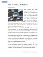
Figure 1.1 – Information System for The Public Transport of Singapore --------------------4
Figure 2.1 – General Architecture of A GSM Network ----------------------------------------12
Figure 2.2 – Organization of bursts, TDMA frames, and multiframes for speech and data ----------------------------------------------------------------------------------------------------------17
Figure 2.3 – Signalling Protocol Structure in GSM --------------------------------------------24
Figure 2.4 – Call Routing for A Mobile Terminating Call ------------------------------------32
Figure 2.5 – Call Basic Network Architecture for An SMS Deployment (IS-41) ----------33
Figure 2.6 – MT – SM Scenario (GSM) ---------------------------------------------------------42
Figure 2.7– MT Short Message Scenario (IS-41) -----------------------------------------------43
Figure 2.8– MO—SM Scenario (GSM) ----------------------------------------------------------44
Figure 2.9– MO—SM Scenario (IS-41) ---------------------------------------------------------45
Figure 3.1 – General System Software Structure------------------------------------------------50
Figure 3.2 – General Prototype System Model -------------------------------------------------53
Figure 3.3 – System Hardware Structure --------------------------------------------------------55
Figure 3.4 – Installation of Nokia PC Connectivity SDK -------------------------------------56
Figure 3.5 – Data Cable Connection to Nokia Phone ------------------------------------------56
Figure 3.6 – Data Cable Connection to PC serial port -----------------------------------------57
Figure 3.7 – Nokia Connection Manager Detection of Nokia 8210--------------------------57
Figure 4.1 – Service Database GUI for Public Service Transport System ------------------67
Figure 4.2 – Service Guide Search Through Road Name -------------------------------------68
Figure 4.3 – Road-to-Road Service Guide -------------------------------------------------------68
xi
Figure 4.4 – Stop-to-Road Service Guide with Bus Service Transfer -----------------------69
Figure 4.5 – Bus Arrival Times -------------------------------------------------------------------71
Figure 4.6 – Bus Flagging -------------------------------------------------------------------------71
Figure 4.7 – SMS Alert When Reaching Specific Stop ----------------------------------------71
Figure 4.8 – Prototype Road Map with Car Parks ----------------------------------------------77
Figure 4.9 – Car Parks’ Capacity Information --------------------------------------------------78
Figure 4.10 – Parking Request and Start of Parking Procedure -------------------------------79
Figure 4.11 – End of Parking Procedure and Billing Information ----------------------------79
Figure 4.12 – MRT Arrivals Information to Changi Airport Station -------------------------84
Figure 4.13 – MRT Arrivals Information based on Flight Departure ------------------------85
Figure 4.14 – Registering Mobile Phone Number to the Database ---------------------------91
Figure 4.15 – Illegal Parking Fine Procedure ---------------------------------------------------92
Figure 4.16 – Registering into ERP Billing System --------------------------------------------98
Figure 4.17 – Acknowledgement of Payment from ERP Billing System -------------------99
Figure 4.18 – Vehicle security Alert to Motorist ----------------------------------------------105
Figure 4.19 – Vehicle security Alert to Police -------------------------------------------------105
Figure 4.20 – Location-to-Location Query for Singapore Street Directory System ------110
Figure 4.21 – Location-to-Location Query in Case of Traffic Jam -------------------------111
xii
1 INTRODUCTION
Although technology is changing rapidly, and communications channels and
computers are adapting to the increased interest in colour images, voice and video with
many exciting applications being introduced, one wireless technology has taken
everyone in the mobile industry by surprise – Short Messaging Service (SMS).
Few people predicted that this difficult of use service would take off. There was hardly
any promotion for or mention of SMS by network operators until after SMS started to
be successful. SMS advertising went from showing business people in suits entering
text messages to bright pink and yellow advertisements aimed at the youth markets that
adopted SMS.
Today, numerous SMS applications have been realized. One of them is SingTel
SmartStock. It uses SMS service to allow users to inquire for the most current stocks
information. With the service available on demand, users are able to get the stock
information as and when they request it.
Singapore International Airlines (SIA) also uses SMS service to provide worldwide
mobile flight alert services to its users. Users are able to specify the SMS alerts they
would like to receive, such as alerts of flight departures, arrivals, delays or gate
changes.
SBS Transit and SingTel [10] had developed the first SMS bus guide whereby the
information system consists of SBS Transit timings service for this system is able to
automatically determine the sender's location using SingTel GSM base stations around
the country and inform the sender of the available bus services in the vicinity. By
keying in the desired destination, a point-to-point bus travel solution will be provided
1
to the sender. Commuters can also request for the route of any SBS Transit bus service
via this SMS service.
In this thesis, we were looking to use the low cost and universal availability of SMS to
develop new innovative applications for the public transport system in Singapore.
Prototypes were developed and tested to see if it was feasible and user-friendly. These
prototypes were realized with the hardware of a GSM data cable, PC and a mobile
phone. With a suitable program developed for the PC, any mobile phone user can send
SMS to the prototype. The information system formulates a result and sends it back to
the user’s mobile phone.
There were seven applications developed and their prototypes designed and tested in
the thesis:
1) Public service transport system
2) SMRT and Changi Airport
3) Car parking system
4) Illegal parking fining system
5) Vehicle burglar alarm
6) ERP billing system
7) Singapore Street Directory
In the public service transport system, a SMS based information system was designed
to provide an interactive travel guide, which integrated SMRT train and bus service
information. It also provided features like bus arrival times and bus stop reaching alert.
Another SMS based information system was designed to combine airport flight
information with SMRT train service. Passengers who intended to travel to the airport
by SMRT train would be able to check when the SMRT train could take them to the
airport in time for departure.
2
In the car parking system, a SMS based information system was designed to provide
services whereby motorists could pay their parking through SMS; in addition, it
provided information about the capacity of car parks.
In the case of illegal parking, a SMS based information system was designed to book
any illegally parked vehicle and to inform the owner of the automobile through SMS.
A prototype was designed to test out the possibility of the booking and the payment of
fines through SMS.
SMS can be integrated into the vehicle security alert system such that any vehicle theft
would sound off the alarm in a vehicle as well as a SMS alert message to vehicle’s
owner. A prototype was developed and tested out on the application.
In the ERP billing system, a SMS based information system was designed for
Electronic Road Pricing (ERP) payment. The prototype was designed to test out
whether it was a more convenient service than cash card payment, whereby motorists
would not need to worry about topping up their cash card, while payment could be
credited into their phone bills.
For the Singapore street directory, a SMS based information system was designed to
provide location-to-location information through the use of SMS.
1.1 Motivations
The motivation of using SMS to design and develop applications for the public
transport system in Singapore is to integrate a wireless environment into the transport
system. Users will be able to use SMS to look out for travel information; motorists will
be able to check out the traffic situation, car park information and pay parking fees via
SMS; traffic fines by SMS will be easier and faster to process.
3
These applications are to provide simple, fast, efficient and economical ways of
bringing information to people, as well as to make transactions such as payments of
fines easier.
Fig. 1.1 – Information System for The Public Transport of Singapore
Prototypes produced are as close as possible to the actual applications, as they used
GSM data cable and mobile phone connected to the PC. Therefore, actual SMS queries
could be sent to this mobile phone, whereby a program in the PC processes the queries
and provides necessary results, which in turn are sent out using the mobile phone. It is
far more realistic than plain simulations that use software running on the PC.
1.2 Objectives
A prototype should be developed for each application to test out its feasibility. It
should be able to establish communication with any user’s mobile phone using SMS.
4
The thesis was aimed at meeting two main objectives for such an information system
design: hardware and software.
The hardware objectives were as following:
•
The components used should be reliable. The prototype was tested for its
consistency in sending and receiving SMS messages, making sure that the
components did not malfunction.
•
The information that was being sent and received through the components
should be precise and timely. The prototype was tested to see whether the
components were able to convert SMS messages into text messages correctly in
the software programmed on the PC.
The software objectives were as following:
•
The software should be capable of analyzing the SMS message and break it
down into relevant text messages.
•
The software should have a good and accurate database management and
communication with the user’s mobile phone through SMS.
•
The software should be able to perform real-time applications.
•
The software should be capable of arranging the information into one or more
text messages and send it back to the correct user’s mobile phone by SMS.
Constant testing and fine-tuning was required when the prototype’s hardware and
software were integrated together to ensure that the combination produced minimal
erroneous results.
Most importantly, the prototype should be user friendly after integration. Testing was
done to see if a user was able to understand SMS messages received from the
application when the user requested for information. The user should also understand
5
messages and replied accordingly if the application sent SMS options for the user to
choose.
1.3 Organization of the Thesis
The thesis consists of ten chapters.
In Chapter one, we have discussed the benefits of the SMS based information system.
We proposed information systems for the public transport system in Singapore, which
are analyzed and further prototypes are designed and developed. The motivation
factors and objectives for the thesis are also mentioned.
The second chapter focuses on the literature reviews of the GSM system and Short
Message Service. The function of the SMS is included.
In Chapter three, the general prototype system model of the seven SMS applications is
illustrated. In details, the hardware setup of the prototype is also described in this
chapter.
In Chapter four, the seven applications and their prototypes are described in details.
The details include about information how they work, what software modules are
responsible and how they are combined together to respond to a user’s request. A brief
comparison of the seven applications is also mentioned.
Chapter five concentrates on the contributions made during the development of the
prototypes. It concludes with discussion on future work in this field.
6
2 BACKGROUND THEORY
This chapter is organized in the following way: after an overview of the GSM System
and the services it can support, we focus on the characteristics of the SMS, and the
possible set of applications which are based on these characteristics.
2.1 The GSM System
In this chapter, an overview of the GSM system will be presented to give a general
flavour of GSM and the philosophy behind its design. It is a standard that ensures
interoperability without stifling competition and innovation among suppliers, to the
benefit of the public both in terms of cost and service quality. For example, by using
Very Large Scale Integration (VLSI) microprocessor technology, many functions of
the mobile station can be built on one chipset, resulting in lighter, more compact, and
more energy-efficient terminals.
Telecommunications are evolving towards personal communication networks, whose
objective can be stated as the availability of all communication services anytime,
anywhere, to anyone, by a single identity number. Having a multitude of incompatible
systems throughout the world moves us farther away from this ideal. The economies of
scale created by a unified system are enough to justify its implementation, not to
mention the convenience to people of carrying just one communication terminal
anywhere they go, regardless of national boundaries.
The GSM system and its sibling systems operating at 1.8 GHz (called DCS1800) and
1.9 GHz (called GSM1900 or PCS1900, and operating in North America) are a first
approach at a true personal communication system. The SIM card is a novel approach
that implements personal mobility in addition to terminal mobility. Together with
7
international roaming, and support for a variety of services such as telephony, data
transfer, fax, Short Message Service, and supplementary services, GSM comes close to
fulfilling the requirements for a personal communication system: close enough that it
is being used as a basis for the next generation of mobile communication technology in
Europe, the Universal Mobile Telecommunication System (UMTS).
GSM is a very complex standard, but that is probably the price that must be paid to
achieve the level of integrated service and quality offered while subject to the rather
severe restrictions imposed by the radio environment.
2.2 History of GSM
During the early 1980s, analog cellular telephone systems were experiencing rapid
growth in Europe, particularly in Scandinavia and the United Kingdom, but also in
France and Germany. Each country developed its own system, which was incompatible
with everyone else's in equipment and operation. This was an undesirable situation,
because not only was the mobile equipment limited to operation within national
boundaries, which in a unified Europe were increasingly unimportant, but there was
also a very limited market for each type of equipment, so economies of scale and the
subsequent savings could not be realized.
The Europeans realized this early on, and in 1982 the Conference of European Posts
and Telegraphs (CEPT) formed a study group called the Groupe Spécial Mobile
(GSM) to study and develop a pan-European public land mobile system. The proposed
system had to meet certain criteria:
•
Good subjective speech quality
•
Low terminal and service cost
•
Support for international roaming
8
•
Ability to support handheld terminals
•
Support for range of new services and facilities
•
Spectral efficiency
•
ISDN compatibility
In 1989, GSM responsibility was transferred to the European Telecommunication
Standards Institute (ETSI), and phase I of the GSM specifications was published in
1990. Commercial service was started in mid-1991, and by 1993 there were 36 GSM
networks in 22 countries [16]. Although standardized in Europe, GSM is not only a
European standard. Over 200 GSM networks (including DCS1800 and PCS1900) are
operational in 110 countries around the world. In the beginning of 1994, there were 1.3
million subscribers worldwide [18], which had grown to more than 55 million by
October 1997. With North America making a delayed entry into the GSM field with a
derivative of GSM called PCS1900, GSM systems exist on every continent, and the
acronym GSM now aptly stands for Global System for Mobile communications.
The developers of GSM chose an unproven (at the time) digital system, as opposed to
the then-standard analog cellular systems like AMPS in the United States and TACS in
the United Kingdom. They had faith that advancements in compression algorithms and
digital signal processors would allow the fulfillment of the original criteria and the
continual improvement of the system in terms of quality and cost. The over 8000 pages
of GSM recommendations try to allow flexibility and competitive innovation among
suppliers, but provide enough standardization to guarantee proper inter-working
between the components of the system. This is done by providing functional and
interface descriptions for each of the functional entities defined in the system.
9
2.3 Services Provided by GSM
From the beginning, the planners of GSM wanted ISDN compatibility in terms of the
services offered and the control signalling used. However, radio transmission
limitations, in terms of bandwidth and cost, do not allow the standard ISDN B-channel
bit rate of 64 kbps to be practically achieved.
Telecommunication services can be divided into bearer services, teleservices, and
supplementary services. The most basic teleservice supported by GSM is telephony.
As with all other communications, speech is digitally encoded and transmitted through
the GSM network as a digital stream. There is also an emergency service, where the
nearest emergency-service provider is notified by dialing three digits (similar to 911).
A variety of data services are offered. GSM users can send and receive data, at rates up
to 9600 bps, to users on POTS (Plain Old Telephone Service), ISDN, Packet Switched
Public Data Networks, and Circuit Switched Public Data Networks using a variety of
access methods and protocols, such as X.25 or X.32. Since GSM is a digital network, a
modem is not required between the user and GSM network, although an audio modem
is required inside the GSM network to inter-work with POTS.
Other data services include Group 3 facsimile, as described in ITU-T recommendation
T.30, which is supported by use of an appropriate fax adaptor. A unique feature of
GSM, not found in older analog systems, is the Short Message Service (SMS). SMS is
a bi-directional service for short alphanumeric (up to 160 bytes) messages. Messages
are transported in a store-and-forward fashion. For point-to-point SMS, a message can
be sent to another subscriber to the service, and an acknowledgement of receipt is
provided to the sender. SMS can also be used in a cell-broadcast mode, for sending
messages such as traffic updates or news updates. Messages can also be stored in the
SIM card for later retrieval [14].
10
Supplementary services are provided on top of teleservices or bearer services. In the
current (Phase I) specifications, they include several forms of call forward (such as call
forwarding when the mobile subscriber is unreachable by the network), and call
barring of outgoing or incoming calls, for example when roaming in another country.
Many additional supplementary services will be provided in the Phase 2 specifications,
such as caller identification, call waiting, multi-party conversations.
2.4 Architecture of the GSM Network
A GSM network is composed of several functional entities, whose functions and
interfaces are specified. Figure 2.1 shows the layout of a generic GSM network. The
GSM network can be divided into three broad parts. The Mobile Station is carried by
the subscriber. The Base Station Subsystem controls the radio link with the Mobile
Station. The Network Subsystem, the main part of which is the Mobile services
Switching Center (MSC), performs the switching of calls between the mobile users,
and between mobile and fixed network users. The MSC also handles the mobility
management operations. Not shown is the Operations and Maintenance Center, which
oversees the proper operation and setup of the network. The Mobile Station and the
Base Station Subsystem communicate across the Um interface, also known as the air
interface or radio link. The Base Station Subsystem communicates with the Mobile
services Switching Center across the A interface.
11