Service manual - Sách hướng dẫn vận hành sửa chữa VRF Toshiba
Bạn đang xem bản rút gọn của tài liệu. Xem và tải ngay bản đầy đủ của tài liệu tại đây (30.14 MB, 370 trang )
FILE No. A10-005
AIR CONDITIONER (MULTI TYPE)
SERVICE MANUAL
This service manual provides relevant explanations about new outdoor unit (SMMS-i). Please refer to
the following service manuals for each indoor units.
4-way Air Discharge Cassette Type
(MMU-AP
2H)
A08-004
Compact 4-way Cassette (600 × 600) Type
(MMU-AP
1MH)
A06-002
1-way Air Discharge Cassette Type SH (2 series)
(MMU-AP
2SH)
A05-007
2-way Air Discharge Cassette Type (2 series)
(MMU-AP
2WH)
A10-007
Slim Duct Type
(MMD-AP
1SPH)
A05-007
Fresh Air Intake Indoor Unit Type
(MMD-AP
1HFE)
A06-016
High-wall Type (2 series)
(MMK-AP
2H)
A05-005
High-wall Type (3 series)
(MMK-AP
3H)
SVM-09059
Other indoor units
SMMS (1 series) A03-009, A03-010
Outdoor Unit
<SUPER MODULAR MULTI SYSTEM-i>
Model name:
<Heat Pump Model>
MMY-MAP0804HT8(Z)(ZG)-E
MMY-MAP1004HT8(Z)(ZG)-E
MMY-MAP1204HT8(Z)(ZG)-E
MMY-MAP1404HT8(Z)(ZG)-E
MMY-MAP1604HT8(Z)(ZG)-E
MMY-MAP0804HT8(Z)(ZG)-TR
MMY-MAP1004HT8(Z)(ZG)-TR
MMY-MAP1204HT8(Z)(ZG)-TR
MMY-MAP1404HT8(Z)(ZG)-TR
MMY-MAP1604HT8(Z)(ZG)-TR
MMY-MAP0804HT8(Z)(ZG)
MMY-MAP1004HT8(Z)(ZG)
MMY-MAP1204HT8(Z)(ZG)
MMY-MAP1404HT8(Z)(ZG)
MMY-MAP1604HT8(Z)(ZG)
MMY-MAP0804T8(Z)(ZG)
MMY-MAP1004T8(Z)(ZG)
MMY-MAP1204T8(Z)(ZG)
MMY-MAP1404T8(Z)(ZG)
MMY-MAP1604T8(Z)(ZG)
MMY-MAP0804T8-SG
MMY-MAP1004T8-SG
MMY-MAP1204T8-SG
MMY-MAP1404T8-SG
MMY-MAP1604T8-SG
MMY-MAP0804HT7(Z)(ZG)
MMY-MAP1004HT7(Z)(ZG)
MMY-MAP1204HT7(Z)(ZG)
MMY-MAP1404HT7(Z)(ZG)
MMY-MAP1604HT7(Z)(ZG)
<Cooling Only Model>
MMY-MAP0804T8(Z)(ZG)-E
MMY-MAP1004T8(Z)(ZG)-E
MMY-MAP1204T8(Z)(ZG)-E
MMY-MAP1404T8(Z)(ZG)-E
MMY-MAP1604T8(Z)(ZG)-E
Contents
Original instruction . . . . . . . . . . . . . . . . . . . . . . . . . . . . . . . . . . . . . . . . . . . . . . . . . . . . 5
New Refrigerant (R410A). . . . . . . . . . . . . . . . . . . . . . . . . . . . . . . . . . . . . . . . . . . . . . . 21
1 Wiring Diagrams . . . . . . . . . . . . . . . . . . . . . . . . . . . . . . . . . . . . . . . . . . . . . . . . . . . . . 23
1-1. Outdoor Unit . . . . . . . . . . . . . . . . . . . . . . . . . . . . . . . . . . . . . . . . . . . . . . . . . . . . . . . . . . . . . . . . 23
1-2. Indoor Unit . . . . . . . . . . . . . . . . . . . . . . . . . . . . . . . . . . . . . . . . . . . . . . . . . . . . . . . . . . . . . . . . . . 25
1-2-1. 4-way Air Discharge Cassette Type . . . . . . . . . . . . . . . . . . . . . . . . . . . . . . . . . . . . . . . . 25
1-2-2. Compact 4-way Cassette Type . . . . . . . . . . . . . . . . . . . . . . . . . . . . . . . . . . . . . . . . . . . 26
1-2-3. 1-way Air Discharge Cassette Type (Compact type) . . . . . . . . . . . . . . . . . . . . . . . . . . . 27
1-2-4. 1-way Air Discharge Cassette Type SH 2 series . . . . . . . . . . . . . . . . . . . . . . . . . . . . . . 28
1-2-5. 2-way Air Discharge Cassette Type 1 series . . . . . . . . . . . . . . . . . . . . . . . . . . . . . . . . . 29
1-2-6. 2-way Air Discharge Cassette Type 2 series . . . . . . . . . . . . . . . . . . . . . . . . . . . . . . . . . 30
1-2-7. Concealed Duct Standard Type . . . . . . . . . . . . . . . . . . . . . . . . . . . . . . . . . . . . . . . . . . . 31
1-2-8. Concealed Duct High Static Pressure Type . . . . . . . . . . . . . . . . . . . . . . . . . . . . . . . . . . 32
1-2-9. Slim Duct Type . . . . . . . . . . . . . . . . . . . . . . . . . . . . . . . . . . . . . . . . . . . . . . . . . . . . . . . . 34
1-2-10. Under Ceiling Type. . . . . . . . . . . . . . . . . . . . . . . . . . . . . . . . . . . . . . . . . . . . . . . . . . . . . 35
1-2-11. High Wall Type 2 series . . . . . . . . . . . . . . . . . . . . . . . . . . . . . . . . . . . . . . . . . . . . . . . . . 36
1-2-12. High Wall Type 3 series . . . . . . . . . . . . . . . . . . . . . . . . . . . . . . . . . . . . . . . . . . . . . . . . . 37
1-2-13. Floor Standing Cabinet Type . . . . . . . . . . . . . . . . . . . . . . . . . . . . . . . . . . . . . . . . . . . . . 38
1-2-14. Floor Standing Concealed Type. . . . . . . . . . . . . . . . . . . . . . . . . . . . . . . . . . . . . . . . . . . 39
1-2-15. Floor Standing Type . . . . . . . . . . . . . . . . . . . . . . . . . . . . . . . . . . . . . . . . . . . . . . . . . . . . 40
1-2-16. Fresh Air Intake Indoor Unit for S-MMS . . . . . . . . . . . . . . . . . . . . . . . . . . . . . . . . . . . . . 41
2 Parts Rating . . . . . . . . . . . . . . . . . . . . . . . . . . . . . . . . . . . . . . . . . . . . . . . . . . . . . . . . . 43
2-1. Outdoor Unit (50Hz model: MMY-MAP
4HT8-E, MAP
4HT8-TR, MAP
4HT8, MAP
4T8SG) . . . . . . . . . . . . . . . . . . . . . . . . . . . . . . . . . . . . . . . . . . . . . . . . . . . . . . . . . . . . . . . . . . . . . . . 43
2-2. Outdoor Unit (60Hz model: MMY-MAP
4HT7) . . . . . . . . . . . . . . . . . . . . . . . . . . . . . . . . . . . . 44
2-3. Outdoor Inverter (50Hz model: MMY-MAP
4HT8-E, MAP
4HT8-TR, MAP
4HT8,
MAP
4T8-SG) . . . . . . . . . . . . . . . . . . . . . . . . . . . . . . . . . . . . . . . . . . . . . . . . . . . . . . . . . . . . . 45
2-4. Outdoor Inverter (60Hz model: MMY-MAP
4HT7) . . . . . . . . . . . . . . . . . . . . . . . . . . . . . . . . . 46
2-5. Indoor Unit . . . . . . . . . . . . . . . . . . . . . . . . . . . . . . . . . . . . . . . . . . . . . . . . . . . . . . . . . . . . . . . . . . 47
2-6. Parts Layout in Outdoor Unit . . . . . . . . . . . . . . . . . . . . . . . . . . . . . . . . . . . . . . . . . . . . . . . . . . . . 53
2-7. Parts Layout in Inverter Assembly . . . . . . . . . . . . . . . . . . . . . . . . . . . . . . . . . . . . . . . . . . . . . . . . 55
2-8. Outdoor (Inverter) Print Circuit Board . . . . . . . . . . . . . . . . . . . . . . . . . . . . . . . . . . . . . . . . . . . . . 57
2-8-1. Interface P.C. board (MCC-1606) . . . . . . . . . . . . . . . . . . . . . . . . . . . . . . . . . . . . . . . . . 57
2-8-2. Inverter P.C. board for compressor (MCC-1596) A3-IPDU . . . . . . . . . . . . . . . . . . . . . . 58
2-8-3. Inverter P.C. board for fan (MCC-1610) . . . . . . . . . . . . . . . . . . . . . . . . . . . . . . . . . . . . . 59
3 Refrigerant Piping Systematic Drawing . . . . . . . . . . . . . . . . . . . . . . . . . . . . . . . . . . 60
4 Combined Refrigerant Piping System Schematic Diagrams. . . . . . . . . . . . . . . . . . 64
1
4-1. Normal Operation (COOL Mode / DEFROST Mode) - High Outside Air Temperature (Roughly 20
°C or Above) . . . . . . . . . . . . . . . . . . . . . . . . . . . . . . . . . . . . . . . . . . . . . . . . . . . . . . . . . . . . . . . . 64
4-2. Normal Operation (COOL Mode) - Low Outside Air Temperature (Roughly Below 20 °C) . . . . . 65
4-3. Normal Operation (HEAT Mode) . . . . . . . . . . . . . . . . . . . . . . . . . . . . . . . . . . . . . . . . . . . . . . . . . 66
4-4. Emergency Operation (Cooling Operation under Header Outdoor Unit Backup Scenario). . . . . 67
4-5. Emergency Operation (Heating Operation under Header Outdoor Unit Backup Scenario). . . . . 68
4-6. Refrigerant Recovery from Failed Outdoor Unit (Pump-Down Operation under Follower Outdoor
Unit Backup Scenario) . . . . . . . . . . . . . . . . . . . . . . . . . . . . . . . . . . . . . . . . . . . . . . . . . . . . . . . . . 69
5 Control Outline. . . . . . . . . . . . . . . . . . . . . . . . . . . . . . . . . . . . . . . . . . . . . . . . . . . . . . . 70
6 Applied Control and Functions (including Circuit Configuration) . . . . . . . . . . . . . 85
6-1. Indoor Controller Block Diagram . . . . . . . . . . . . . . . . . . . . . . . . . . . . . . . . . . . . . . . . . . . . . . . . . 85
6-1-1. When Main (Sub) Remote Controller Connected . . . . . . . . . . . . . . . . . . . . . . . . . . . . . . 85
6-1-2. When Wireless Remote Controller Kit Connected . . . . . . . . . . . . . . . . . . . . . . . . . . . . . 88
6-1-3. When Both Main (Sub) Remote Controller and Wireless Remote Controller Kit Connected .91
6-2. Indoor Printed Circuit Board . . . . . . . . . . . . . . . . . . . . . . . . . . . . . . . . . . . . . . . . . . . . . . . . . . . . 94
6-3. Optional Connector Specifications of Indoor P.C. Board. . . . . . . . . . . . . . . . . . . . . . . . . . . . . . . 97
6-4. Test Operation of Indoor Unit . . . . . . . . . . . . . . . . . . . . . . . . . . . . . . . . . . . . . . . . . . . . . . . . . . . 98
6-5. Method to Set Indoor Unit Function DN Code . . . . . . . . . . . . . . . . . . . . . . . . . . . . . . . . . . . . . . . 99
6-6. Applied Control of Indoor Unit . . . . . . . . . . . . . . . . . . . . . . . . . . . . . . . . . . . . . . . . . . . . . . . . . 103
6-7. Applied control for Outdoor Unit . . . . . . . . . . . . . . . . . . . . . . . . . . . . . . . . . . . . . . . . . . . . . . . . 106
6-7-1. Outdoor Fan High Static Pressure Shift . . . . . . . . . . . . . . . . . . . . . . . . . . . . . . . . . . . . 106
6-7-2. Priority Operation Mode Setting . . . . . . . . . . . . . . . . . . . . . . . . . . . . . . . . . . . . . . . . . . 107
6-8. Applied Control of Outdoor Unit. . . . . . . . . . . . . . . . . . . . . . . . . . . . . . . . . . . . . . . . . . . . . . . . . 109
6-8-1. Power peak-cut Control (Standard) . . . . . . . . . . . . . . . . . . . . . . . . . . . . . . . . . . . . . . . 110
6-8-2. Power peak-cut Control (Extended) . . . . . . . . . . . . . . . . . . . . . . . . . . . . . . . . . . . . . . . 111
6-8-3. Snowfall Fan Control . . . . . . . . . . . . . . . . . . . . . . . . . . . . . . . . . . . . . . . . . . . . . . . . . . 112
6-8-4. External master ON/OFF Control . . . . . . . . . . . . . . . . . . . . . . . . . . . . . . . . . . . . . . . . . 112
6-8-5. Night operation (sound reduction) Control . . . . . . . . . . . . . . . . . . . . . . . . . . . . . . . . . . 113
6-8-6. Operation Mode Selection Control . . . . . . . . . . . . . . . . . . . . . . . . . . . . . . . . . . . . . . . . 114
6-8-7. Error/Operation Output. . . . . . . . . . . . . . . . . . . . . . . . . . . . . . . . . . . . . . . . . . . . . . . . . 115
6-8-8. Compressor Operation Output . . . . . . . . . . . . . . . . . . . . . . . . . . . . . . . . . . . . . . . . . . . 116
6-8-9. Operating Rate Output . . . . . . . . . . . . . . . . . . . . . . . . . . . . . . . . . . . . . . . . . . . . . . . . . 117
7 TEST OPERATION . . . . . . . . . . . . . . . . . . . . . . . . . . . . . . . . . . . . . . . . . . . . . . . . . . . 118
7-1. Procedure and Summary of Test Operation . . . . . . . . . . . . . . . . . . . . . . . . . . . . . . . . . . . . . . . 118
7-2. Check Items before Test Operation (before powering-on) . . . . . . . . . . . . . . . . . . . . . . . . . . . . 119
7-3. Check at Main Power-on . . . . . . . . . . . . . . . . . . . . . . . . . . . . . . . . . . . . . . . . . . . . . . . . . . . . . . 123
7-4. Address Setup . . . . . . . . . . . . . . . . . . . . . . . . . . . . . . . . . . . . . . . . . . . . . . . . . . . . . . . . . . . . . . 124
7-4-1. Precautions . . . . . . . . . . . . . . . . . . . . . . . . . . . . . . . . . . . . . . . . . . . . . . . . . . . . . . . . . 124
7-4-2. Address Setup and Check Procedure . . . . . . . . . . . . . . . . . . . . . . . . . . . . . . . . . . . . . 124
7-4-3. Address Setup Procedure . . . . . . . . . . . . . . . . . . . . . . . . . . . . . . . . . . . . . . . . . . . . . . 125
7-4-4. Check after Address Setup when Central Control System Is Connected . . . . . . . . . . 138
2
7-5. Troubleshooting in Test Operation . . . . . . . . . . . . . . . . . . . . . . . . . . . . . . . . . . . . . . . . . . . . . . 139
7-5-1. A Check Code Is Displayed on the Remote Controller . . . . . . . . . . . . . . . . . . . . . . . . 139
7-5-2. Operation from the indoor remote controller is not accepted, and a check code is displayed
on the 7-segment display of the interface PC board of the header unit. . . . . . . . . . . . 140
7-5-3. There is no display of a check code on the 7-segment display on the interface PC board of
the header unit, although there is indoor unit that is not accepting operation from the indoor
remote controller. . . . . . . . . . . . . . . . . . . . . . . . . . . . . . . . . . . . . . . . . . . . . . . . . . . . . . 140
7-5-4. In checking the number of connected outdoor units and connected indoor units after address setup, a lower number of connected units is displayed. (There are outdoor/indoor
units that do not operate in a test operation.). . . . . . . . . . . . . . . . . . . . . . . . . . . . . . . . 141
7-6. Test Operation Check . . . . . . . . . . . . . . . . . . . . . . . . . . . . . . . . . . . . . . . . . . . . . . . . . . . . . . . . 143
7-6-1. Fan Check . . . . . . . . . . . . . . . . . . . . . . . . . . . . . . . . . . . . . . . . . . . . . . . . . . . . . . . . . . 143
7-6-2. Cooling/Heating Test Operation Check . . . . . . . . . . . . . . . . . . . . . . . . . . . . . . . . . . . . 144
7-7. Service Support Function . . . . . . . . . . . . . . . . . . . . . . . . . . . . . . . . . . . . . . . . . . . . . . . . . . . . . 148
7-7-1. Check Function for Connecting of Refrigerant and Control Lines . . . . . . . . . . . . . . . . 148
7-7-2. Function to Start/Stop (ON/OFF) Indoor Unit from Outdoor Unit . . . . . . . . . . . . . . . . . 150
7-7-3. Error Clearing Function . . . . . . . . . . . . . . . . . . . . . . . . . . . . . . . . . . . . . . . . . . . . . . . . 155
7-7-4. Remote Controller Distinction Function . . . . . . . . . . . . . . . . . . . . . . . . . . . . . . . . . . . . 157
7-7-5. Pulse Motor Valve (PMV) Forced Open/Close Function in Indoor Unit . . . . . . . . . . . . 158
7-7-6. Pulse Motor Valve (PMV) Forced Open Fully/Close fully Function in Outdoor Unit . . . 158
7-7-7. Solenoid Valve Forced Open/Close Function in Outdoor Unit . . . . . . . . . . . . . . . . . . . 159
7-7-8. Fan Operation Check in Outdoor Unit . . . . . . . . . . . . . . . . . . . . . . . . . . . . . . . . . . . . . 160
7-7-9. Abnormal Outdoor Unit Discrimination Method By Fan Operating Function . . . . . . . . 161
7-7-10. Manual Adjustment Function of Outside Temperature (TO) Sensor . . . . . . . . . . . . . . 162
7-7-11. Monitor Function of Remote Controller Switch. . . . . . . . . . . . . . . . . . . . . . . . . . . . . . . 164
8 TROUBLESHOOTING . . . . . . . . . . . . . . . . . . . . . . . . . . . . . . . . . . . . . . . . . . . . . . . . 166
8-1. Overview . . . . . . . . . . . . . . . . . . . . . . . . . . . . . . . . . . . . . . . . . . . . . . . . . . . . . . . . . . . . . . . . . . 166
8-2. Troubleshooting Method . . . . . . . . . . . . . . . . . . . . . . . . . . . . . . . . . . . . . . . . . . . . . . . . . . . . . . 167
8-3. Troubleshooting Based on Information Displayed on Remote Controller . . . . . . . . . . . . . . . . . 173
8-4. Check Codes Displayed on Remote Controller and SMMS-i Outdoor Unit (7-Segment Display on I/
F Board) and Locations to Be Checked. . . . . . . . . . . . . . . . . . . . . . . . . . . . . . . . . . . . . . . . . . . 178
8-5. Diagnosis procedure for each check code . . . . . . . . . . . . . . . . . . . . . . . . . . . . . . . . . . . . . . . . 194
8-6. 7-Segment Display Function . . . . . . . . . . . . . . . . . . . . . . . . . . . . . . . . . . . . . . . . . . . . . . . . . . . 225
8-7. Oil Level Judgment Display . . . . . . . . . . . . . . . . . . . . . . . . . . . . . . . . . . . . . . . . . . . . . . . . . . . . 231
8-8. Leakage/Clogging of Refrigerating Cycle Circuit . . . . . . . . . . . . . . . . . . . . . . . . . . . . . . . . . . . . 232
8-9. Sensor Characteristics . . . . . . . . . . . . . . . . . . . . . . . . . . . . . . . . . . . . . . . . . . . . . . . . . . . . . . . 236
8-10. Pressure Sensor Output Check . . . . . . . . . . . . . . . . . . . . . . . . . . . . . . . . . . . . . . . . . . . . . . . . . 239
9 BACKUP OPERATION (EMERGENCY OPERATION) . . . . . . . . . . . . . . . . . . . . . . . 241
9-1. Note for Backup Operation . . . . . . . . . . . . . . . . . . . . . . . . . . . . . . . . . . . . . . . . . . . . . . . . . . . . 241
9-2. Compressor Backup Operation Setting . . . . . . . . . . . . . . . . . . . . . . . . . . . . . . . . . . . . . . . . . . . 242
9-3. Outdoor Unit Backup Operation Setting . . . . . . . . . . . . . . . . . . . . . . . . . . . . . . . . . . . . . . . . . . 243
9-3-1. Follower outdoor unit backup operation setting (failure of follower outdoor unit) . . . . . 243
9-3-2. Header outdoor unit backup operation setting (failure of header outdoor unit) . . . . . . 245
3
9-4. Cooling-Season Outdoor Unit Backup Operation Setting . . . . . . . . . . . . . . . . . . . . . . . . . . . . . 247
10 OUTDOOR UNIT REFRIGERANT RECOVERY METHOD . . . . . . . . . . . . . . . . . . . . 248
10-1. Refrigerant Recovery from Failed Outdoor Unit (Pump-Down) . . . . . . . . . . . . . . . . . . . . . . . . . 248
10-1-1. Note for refrigerant recovery operation . . . . . . . . . . . . . . . . . . . . . . . . . . . . . . . . . . . . 248
10-1-2. Refrigerant recovery procedure A (Case of no outdoor unit backup operation setting) 248
10-1-3. Refrigerant recovery procedure B (Case of outdoor unit backup operation setting) . . 251
10-2. How to Operate System While Failed Outdoor Unit Being Repaired. . . . . . . . . . . . . . . . . . . . . 253
10-3. Work procedure after Repair . . . . . . . . . . . . . . . . . . . . . . . . . . . . . . . . . . . . . . . . . . . . . . . . . . . 254
11 REPLACING COMPRESSORS . . . . . . . . . . . . . . . . . . . . . . . . . . . . . . . . . . . . . . . . . 255
11-1. Compressor Replacement Procedure (Outline). . . . . . . . . . . . . . . . . . . . . . . . . . . . . . . . . . . . . 255
11-2. Replacement of Compressors . . . . . . . . . . . . . . . . . . . . . . . . . . . . . . . . . . . . . . . . . . . . . . . . . . 256
11-3. Check Procedure to Search Cause of Compressor Oil Shortage . . . . . . . . . . . . . . . . . . . . . . . 260
12 OUTDOOR UNIT PARTS REPLACEMENT METHODS . . . . . . . . . . . . . . . . . . . . . . 263
13 P.C. BOARD EXCHANGE PROCEDURES . . . . . . . . . . . . . . . . . . . . . . . . . . . . . . . . 276
13-1. Replacement of Indoor P.C. Boards . . . . . . . . . . . . . . . . . . . . . . . . . . . . . . . . . . . . . . . . . . . . . 276
13-2. Replacement of Outdoor P.C. Boards . . . . . . . . . . . . . . . . . . . . . . . . . . . . . . . . . . . . . . . . . . . . 283
13-2-1. List of service P.C. boards . . . . . . . . . . . . . . . . . . . . . . . . . . . . . . . . . . . . . . . . . . . . . . 283
13-2-2. Configuration of inverter assembly . . . . . . . . . . . . . . . . . . . . . . . . . . . . . . . . . . . . . . . . 283
13-2-3. Interface board (MCC-1606) replacement method. . . . . . . . . . . . . . . . . . . . . . . . . . . . 284
13-2-4. Comp-IPDU P.C. Board (MCC-1596) Replacement Procedure . . . . . . . . . . . . . . . . . . 285
13-2-5. Fan IPDU P.C. Board (MCC-1610) Replacement Procedure . . . . . . . . . . . . . . . . . . . 287
13-2-6. Noise Filter P.C. Board (MCC-1608 A, B) Replacement Procedure . . . . . . . . . . . . . . 288
14 EXPLODED DIAGRAM/PARTS PRICE LIST. . . . . . . . . . . . . . . . . . . . . . . . . . . . . . . 291
4
Original instruction
Please read carefully through these instructions that contain important information which complies with the
“Machinery” Directive (Directive 2006/42/EC), and ensure that you understand them.
Some of the details provided in these instructions differ from the service manual, and the instructions provided here
take precedence.
Generic Denomination: Air Conditioner
Definition of Qualified Installer or Qualified Service Person
The air conditioner must be installed, maintained, repaired and removed by a qualified installer or qualified service
person. When any of these jobs is to be done, ask a qualified installer or qualified service person to do them for you.
A qualified installer or qualified service person is an agent who has the qualifications and knowledge described in
the table below.
Agent
Qualifications and knowledge which the agent must have
Qualified installer
• The qualified installer is a person who installs, maintains, relocates and removes the air conditioners
made by Toshiba Carrier Corporation. He or she has been trained to install, maintain, relocate and
remove the air conditioners made by Toshiba Carrier Corporation or, alternatively, he or she has been
instructed in such operations by an individual or individuals who have been trained and is thus
thoroughly acquainted with the knowledge related to these operations.
• The qualified installer who is allowed to do the electrical work involved in installation, relocation and
removal has the qualifications pertaining to this electrical work as stipulated by the local laws and
regulations, and he or she is a person who has been trained in matters relating to electrical work on
the air conditioners made by Toshiba Carrier Corporation or, alternatively, he or she has been
instructed in such matters by an individual or individuals who have been trained and is thus thoroughly
acquainted with the knowledge related to this work.
• The qualified installer who is allowed to do the refrigerant handling and piping work involved in
installation, relocation and removal has the qualifications pertaining to this refrigerant handling and
piping work as stipulated by the local laws and regulations, and he or she is a person who has been
trained in matters relating to refrigerant handling and piping work on the air conditioners made by
Toshiba Carrier Corporation or, alternatively, he or she has been instructed in such matters by an
individual or individuals who have been trained and is thus thoroughly acquainted with the knowledge
related to this work.
• The qualified installer who is allowed to work at heights has been trained in matters relating to working
at heights with the air conditioners made by Toshiba Carrier Corporation or, alternatively, he or she
has been instructed in such matters by an individual or individuals who have been trained and is thus
thoroughly acquainted with the knowledge related to this work.
Qualified service
person
• The qualified service person is a person who installs, repairs, maintains, relocates and removes the
air conditioners made by Toshiba Carrier Corporation. He or she has been trained to install, repair,
maintain, relocate and remove the air conditioners made by Toshiba Carrier Corporation or,
alternatively, he or she has been instructed in such operations by an individual or individuals who have
been trained and is thus thoroughly acquainted with the knowledge related to these operations.
• The qualified service person who is allowed to do the electrical work involved in installation, repair,
relocation and removal has the qualifications pertaining to this electrical work as stipulated by the local
laws and regulations, and he or she is a person who has been trained in matters relating to electrical
work on the air conditioners made by Toshiba Carrier Corporation or, alternatively, he or she has been
instructed in such matters by an individual or individuals who have been trained and is thus thoroughly
acquainted with the knowledge related to this work.
• The qualified service person who is allowed to do the refrigerant handling and piping work involved in
installation, repair, relocation and removal has the qualifications pertaining to this refrigerant handling
and piping work as stipulated by the local laws and regulations, and he or she is a person who has
been trained in matters relating to refrigerant handling and piping work on the air conditioners made
by Toshiba Carrier Corporation or, alternatively, he or she has been instructed in such matters by an
individual or individuals who have been trained and is thus thoroughly acquainted with the knowledge
related to this work.
• The qualified service person who is allowed to work at heights has been trained in matters relating to
working at heights with the air conditioners made by Toshiba Carrier Corporation or, alternatively, he
or she has been instructed in such matters by an individual or individuals who have been trained and
is thus thoroughly acquainted with the knowledge related to this work.
5
Definition of Protective Gear
When the air conditioner is to be transported, installed, maintained, repaired or removed, wear protective gloves
and ‘safety’ work clothing.
In addition to such normal protective gear, wear the protective gear described below when undertaking the special
work detailed in the table below.
Failure to wear the proper protective gear is dangerous because you will be more susceptible to injury, burns,
electric shocks and other injuries.
Work undertaken
Protective gear worn
All types of work
Protective gloves
‘Safety’ working clothing
Electrical-related work
Gloves to provide protection for electricians and from heat
Insulating shoes
Clothing to provide protection from electric shock
Work done at heights
(50 cm or more)
Helmets for use in industry
Transportation of heavy objects
Shoes with additional protective toe cap
Repair of outdoor unit
Gloves to provide protection for electricians and from heat
The important contents concerned to the safety are described on the product itself and on this Service Manual.
Please read this Service Manual after understanding the described items thoroughly in the following contents
(Indications/Illustrated marks), and keep them.
[Explanation of indications]
Indication
Explanation
DANGER
Indicates contents assumed that an imminent danger causing a death or serious injury of
the repair engineers and the third parties when an incorrect work has been executed.
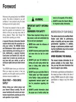
WARNING
Indicates possibilities assumed that a danger causing a death or serious injury of the
repair engineers, the third parties, and the users due to troubles of the product after work
when an incorrect work has been executed.
CAUTION
Indicates contents assumed that an injury or property damage (*) may be caused on the
repair engineers, the third parties, and the users due to troubles of the product after work
when an incorrect work has been executed.
* Property damage: Enlarged damage concerned to property, furniture, and domestic animal/pet
[Explanation of illustrated marks]
Mark
Explanation
Indicates prohibited items (Forbidden items to do)
The sentences near an illustrated mark describe the concrete prohibited contents.
Indicates mandatory items (Compulsory items to do)
The sentences near an illustrated mark describe the concrete mandatory contents.
Indicates cautions (Including danger/warning)
The sentences or illustration near or in an illustrated mark describe the concrete cautious contents.
6
Warning Indications on the Air Conditioner Unit
[Confirmation of warning label on the main unit]
Confirm that labels are indicated on the specified positions
If removing the label during parts replace, stick it as the original.
Warning indication
WARNING
ELECTRICAL SHOCK HAZARD
Disconnect all remote
electric power supplies
before servicing.
WARNING
Moving parts.
Do not operate unit with grille
removed.
Stop the unit before the servicing.
CAUTION
High temperature parts.
You might get burned
when removing this panel.
CAUTION
Do not touch the aluminum
fins of the unit.
Doing so may result in injury.
CAUTION
BURST HAZARD
Open the service valves before
the operation, otherwise there
might be the burst.
CAUTION
Do not climb onto the
fan guard.
Doing so may result in injury.
Description
WARNING
ELECTRICAL SHOCK HAZARD
Disconnect all remote electric power supplies before servicing.
WARNING
Moving parts.
Do not operate unit with grille removed.
Stop the unit before the servicing.
CAUTION
High temperature parts.
You might get burned when removing this panel.
CAUTION
Do not touch the aluminium fins of the unit.
Doing so may result in injury.
CAUTION
BURST HAZARD
Open the service valves before the operation, otherwise there might be the
burst.
CAUTION
Do not climb onto the fan guard.
Doing so may result in injury.
7
Precautions for Safety
The manufacturer shall not assume any liability for the damage caused by not observing the description of this
manual.
DANGER
Before carrying out the installation, maintenance, repair or removal work, be sure to set the circuit breaker for
both the indoor and outdoor units to the OFF position. Otherwise, electric shocks may result.
Before opening the intake grille of the indoor unit or service panel of the outdoor unit, set the circuit breaker to
the OFF position.
Failure to set the circuit breaker to the OFF position may result in electric shocks through contact with the interior
parts.
Only a qualified installer (*1) or qualified service person (*1) is allowed to remove the intake grille of the indoor
unit or service panel of the outdoor unit and do the work required.
Before starting to repair the outdoor unit fan or fan guard, be absolutely sure to set the circuit
breaker to the OFF position, and place a “Work in progress” sign on the circuit breaker.
Turn off
breaker.
When cleaning the filter or other parts of the indoor unit, set the circuit breaker to OFF without
fail, and place a “Work in progress” sign near the circuit breaker before proceeding with the work.
When you have noticed that some kind of trouble (such as when an error display has appeared, there is a smell
of burning, abnormal sounds are heard, the air conditioner fails to cool or heat or water is leaking) has occurred
in the air conditioner, do not touch the air conditioner yourself but set the circuit breaker to the OFF position,
and contact a qualified service person. Take steps to ensure that the power will not be turned on (by marking
“out of service” near the circuit breaker, for instance) until qualified service person arrives. Continuing to use the
air conditioner in the trouble status may cause mechanical problems to escalate or result in electric shocks or
other failure.
When you access inside of the service panel to repair electric parts, wait for about five minutes after turning off
the breaker. Do not start repairing immediately.Otherwise you may get electric shock by touching terminals of
Electric shock high-voltage capacitors. Natural discharge of the capacitor takes about five minutes.
hazard
Place a “Work in progress” sign near the circuit breaker while the installation, maintenance, repair or removal
work is being carried out.
There is a danger of electric shocks if the circuit breaker is set to ON by mistake.
Prohibition
Stay on
protection
Before operating the air conditioner after having completed the work, check that the electrical parts box cover
of the indoor unit and service panel of the outdoor unit are closed, and set the circuit breaker to the ON position.
You may receive an electric shock if the power is turned on without first conducting these checks.
If, in the course of carrying out repairs, it becomes absolutely necessary to check out the electrical parts with
the electrical parts box cover of one or more of the indoor units and the service panel of the outdoor unit
removed in order to find out exactly where the trouble lies, wear insulated heat-resistant gloves, insulated boots
and insulated work overalls, and take care to avoid touching any live parts.
You may receive an electric shock if you fail to heed this warning. Only qualified service person (*1) is allowed
to do this kind of work.
8
WARNING
Before starting to repair the air conditioner, read carefully through the Service Manual, and repair the air
conditioner by following its instructions.
Only qualified service person (*1) is allowed to repair the air conditioner.
Repair of the air conditioner by unqualified person may give rise to a fire, electric shocks, injury, water leaks
and/or other problems.
Do not use any refrigerant different from the one specified for complement or replacement.
Otherwise, abnormally high pressure may be generated in the refrigeration cycle, which may result in a failure
or explosion of the product or an injury to your body.
Only a qualified installer (*1) or qualified service person (*1) is allowed to carry out the electrical work of the air
conditioner.
Under no circumstances must this work be done by an unqualified individual since failure to carry out the work
properly may result in electric shocks and/or electrical leaks.
When transporting the air conditioner, wear shoes with protective toe caps, protective gloves and other
protective clothing.
When connecting the electrical wires, repairing the electrical parts or undertaking other electrical jobs, wear
gloves to provide protection for electricians and from heat, insulating shoes and clothing to provide protection
from electric shocks.
Failure to wear this protective gear may result in electric shocks.
Electrical wiring work shall be conducted according to law and regulation in the community and installation
manual. Failure to do so may result in electrocution or short circuit.
Only a qualified installer (*1) or qualified service person (*1) is allowed to undertake work at
heights using a stand of 50 cm or more or to remove the intake grille of the indoor unit to
undertake work.
General
When working at heights, use a ladder which complies with the ISO 14122 standard, and follow the procedure
in the ladder’s instructions.
Also wear a helmet for use in industry as protective gear to undertake the work.
When working at heights, put a sign in place so that no-one will approach the work location, before proceeding
with the work.
Parts and other objects may fall from above, possibly injuring a person below.
When executing address setting, test run, or troubleshooting through the checking window on the electric parts
box, put on insulated gloves to provide protection from electric shock. Otherwise you may receive an electric
shock.
Do not touch the aluminum fin of the outdoor unit.
You may injure yourself if you do so. If the fin must be touched for some reason, first put on protective gloves
and safety work clothing, and then proceed.
Do not climb onto or place objects on top of the outdoor unit.
You may fall or the objects may fall off of the outdoor unit and result in injury.
When transporting the air conditioner, wear shoes with additional protective toe caps.
When transporting the air conditioner, do not take hold of the bands around the packing carton.
You may injure yourself if the bands should break.
Be sure that a heavy unit (10kg or heavier) such as a compressor is carried by two persons.
This air conditioner has passed the pressure test as specified in IEC 60335-2-40 Annex EE.
Before troubleshooting or repair work, check the earth wire is connected to the earth terminals of the main unit,
otherwise an electric shock is caused when a leak occurs.If the earth wire is not correctly connected, contact
an electric engineer for rework.
After completing the repair or relocation work, check that the ground wires are connected properly.
Check earth
wires.
Prohibition of
modification.
Be sure to connect earth wire. (Grounding work) Incomplete grounding causes an electric shock.
Do not connect ground wires to gas pipes, water pipes, and lightning rods or ground wires for telephone wires.
Do not modify the products.Do not also disassemble or modify the parts.
It may cause a fire, electric shock or injury.
9
When any of the electrical parts are to be replaced, ensure that the replacement parts satisfy the specifications
given in the Service Manual (or use the parts contained on the parts list in the Service Manual).
Use of any parts which do not satisfy the required specifications may give rise to electric shocks, smoking and/
Use specified or a fire.
parts.
If, in the course of carrying out repairs, it becomes absolutely necessary to check out the electrical parts with
the electrical parts box cover of one or more of the indoor units and the service panel of the outdoor unit
removed in order to find out exactly where the trouble lies, put a sign in place so that no-one will approach the
Do not bring a
child close to work location before proceeding with the work. Third-party individuals may enter the work site and receive
electric shocks if this warning is not heeded.
the
equipment.
Insulating
measures
No fire
Connect the cut-off lead wires with crimp contact, etc., put the closed end side upward and then apply a watercut method, otherwise a leak or production of fire is caused at the users’ side.
When performing repairs using a gas burner, replace the refrigerant with nitrogen gas because the oil that coats
the pipes may otherwise burn.
When repairing the refrigerating cycle, take the following measures.
1) Be attentive to fire around the cycle. When using a gas stove, etc., be sure to put out fire before work;
otherwise the oil mixed with refrigerant gas may catch fire.
2) Do not use a welder in the closed room. When using it without ventilation, carbon monoxide poisoning may
be caused.
3) Do not bring inflammables close to the refrigerant cycle, otherwise fire of the welder may catch the
inflammables.
The refrigerant used by this air conditioner is the R410A.
Check the used refrigerant name and use tools and materials of the parts which match with it.
For the products which use R410A refrigerant, the refrigerant name is indicated at a position on the outdoor unit
where is easy to see. To prevent miss-charging, the route of the service port is changed from one of the former
R22.
For an air conditioner which uses R410A, never use other refrigerant than R410A. For an air conditioner which
uses other refrigerant (R22, etc.), never use R410A.
If different types of refrigerant are mixed, abnormal high pressure generates in the refrigerating cycle and an
injury due to breakage may be caused.
When the air conditioner has been installed or relocated, follow the instructions in the Installation Manual and
purge the air completely so that no gases other than the refrigerant will be mixed in the refrigerating cycle.
Failure to purge the air completely may cause the air conditioner to malfunction.
Refrigerant
Do not charge refrigerant additionally. If charging refrigerant additionally when refrigerant gas leaks, the
refrigerant composition in the refrigerating cycle changes resulted in change of air conditioner characteristics or
refrigerant over the specified standard amount is charged and an abnormal high pressure is applied to the inside
of the refrigerating cycle resulted in cause of breakage or injury. Therefore if the refrigerant gas leaks, recover
the refrigerant in the air conditioner, execute vacuuming, and then newly recharge the specified amount of liquid
refrigerant.
In this time, never charge the refrigerant over the specified amount.
When recharging the refrigerant in the refrigerating cycle, do not mix the refrigerant or air other than R410A into
the specified refrigerant. If air or others is mixed with the refrigerant, abnormal high pressure generates in the
refrigerating cycle resulted in cause of injury due to breakage.
After installation work, check the refrigerant gas does not leak. If the refrigerant gas leaks in the room,
poisonous gas generates when gas touches to fire such as fan heater, stove or cocking stove though the
refrigerant gas itself is innocuous.
Never recover the refrigerant into the outdoor unit. When the equipment is moved or repaired, be sure to recover
the refrigerant with recovering device.
The refrigerant cannot be recovered in the outdoor unit; otherwise a serious accident such as breakage or injury
is caused.
Assembly/
Wiring
Insulator
check
After repair work, surely assemble the disassembled parts, and connect and lead the removed wires as before.
Perform the work so that the cabinet or panel does not catch the inner wires.
If incorrect assembly or incorrect wire connection was done, a disaster such as a leak or fire is caused at user’s
side.
After the work has finished, be sure to use an insulation tester set (500V Megger) to check the resistance is
1M: or more between the charge section and the non-charge metal section (Earth position).
If the resistance value is low, a disaster such as a leak or electric shock is caused at user’s side.
10
Ventilation
When the refrigerant gas leaks during work, execute ventilation.
If the refrigerant gas touches to a fire, poisonous gas generates. A case of leakage of the refrigerant and the
closed room full with gas is dangerous because a shortage of oxygen occurs. Be sure to execute ventilation.
When the refrigerant gas leaks, find up the leaked position and repair it surely.
If the leaked position cannot be found up and the repair work is interrupted, pump-down and tighten the service
valve, otherwise the refrigerant gas may leak into the room.
The poisonous gas generates when gas touches to fire such as fan heater, stove or cocking stove though the
refrigerant gas itself is innocuous.
When installing equipment which includes a large amount of charged refrigerant such as a multi air conditioner
in a sub-room, it is necessary that the density does not the limit even if the refrigerant leaks.
If the refrigerant leaks and exceeds the limit density, an accident of shortage of oxygen is caused.
Compulsion
Tighten the flare nut with a torque wrench in the specified manner.
Excessive tighten of the flare nut may cause a crack in the flare nut after a long period, which may result in
refrigerant leakage.
Nitrogen gas must be used for the airtight test.
The charge hose must be connected in such a way that it is not slack.
For the installation/moving/reinstallation work, follow to the Installation Manual.
If an incorrect installation is done, a trouble of the refrigerating cycle, water leak, electric shock or fire is caused.
Once the repair work has been completed, check for refrigerant leaks, and check the insulation resistance and
water drainage.
Then perform a trial run to check that the air conditioner is running properly.
After repair work has finished, check there is no trouble. If check is not executed, a fire, electric shock or injury
may be caused. For a check, turn off the power breaker.
Check after
repair
After repair work (installation of front panel and cabinet) has finished, execute a test run to check there is no
generation of smoke or abnormal sound.
If check is not executed, a fire or an electric shock is caused. Before test run, install the front panel and cabinet.
Be sure to fix the screws back which have been removed for installation or other purposes.
Check the following matters before a test run after repairing piping.
• Connect the pipes surely and there is no leak of refrigerant.
• The valve is opened.
Do not
Running the compressor under condition that the valve closes causes an abnormal high pressure resulted in
operate the damage of the parts of the compressor and etc. and moreover if there is leak of refrigerant at connecting section
unit with the
valve closed. of pipes, the air is sucked and causes further abnormal high pressure resulted in burst or injury.
Only a qualified installer (*1) or qualified service person (*1) is allowed to relocate the air conditioner. It is
dangerous for the air conditioner to be relocated by an unqualified individual since a fire, electric shocks, injury,
water leakage, noise and/or vibration may result.
Check the following items after reinstallation.
1) The earth wire is correctly connected.
2) The power cord is not caught in the product.
3) There is no inclination or unsteadiness and the installation is stable.
Check after
reinstallation If check is not executed, a fire, an electric shock or an injury is caused.
When carrying out the pump-down work shut down the compressor before disconnecting the refrigerant pipe.
Disconnecting the refrigerant pipe with the service valve left open and the compressor still operating will cause
air, etc. to be sucked in, raising the pressure inside the refrigeration cycle to an abnormally high level, and
possibly resulting in reputing, injury, etc.
When the service panel of the outdoor unit is to be opened in order for the compressor or the area around this
part to be repaired immediately after the air conditioner has been shut down, set the circuit breaker to the OFF
position, and then wait at least 10 minutes before opening the service panel.
If you fail to heed this warning, you will run the risk of burning yourself because the compressor pipes and other
parts will be very hot to the touch. In addition, before proceeding with the repair work, wear the kind of insulated
heat-resistant gloves designed to protect electricians.
Take care not to get burned by compressor pipes or other parts when checking the cooling cycle while running
the unit as they get heated while running. Be sure to put on gloves providing protection for electric shock and
heat.
Cooling check When the service panel of the outdoor unit is to be opened in order for the fan motor, reactor, inverter or the
areas around these parts to be repaired immediately after the air conditioner has been shut down, set the circuit
breaker to the OFF position, and then wait at least 10 minutes before opening the service panel.
If you fail to heed this warning, you will run the risk of burning yourself because the fan motor, reactor, inverter
heat sink and other parts will be very hot to the touch.
In addition, before proceeding with the repair work, wear the kind of insulated heat-resistant gloves designed to
protect electricians.
11
Only a qualified installer (*1) or qualified service person (*1) is allowed to install the air conditioner. If the air
conditioner is installed by an unqualified individual, a fire, electric shocks, injury, water leakage, noise and/or
vibration may result.
Before starting to install the air conditioner, read carefully through the Installation Manual, and follow its
instructions to install the air conditioner.
Be sure to use the company-specified products for the separately purchased parts. Use of non-specified
products may result in fire, electric shock, water leakage or other failure. Have the installation performed by a
qualified installer.
Do not supply power from the power terminal block equipped on the outdoor unit to another outdoor unit.
Capacity overflow may occur on the terminal block and may result in fire.
Do not install the air conditioner in a location that may be subject to a risk of expire to a combustible gas.
If a combustible gas leaks and becomes concentrated around the unit, a fire may occur.
Installation
Install the indoor unit at least 2.5 m above the floor level since otherwise the users may injure themselves or
receive electric shocks if they poke their fingers or other objects into the indoor unit while the air conditioner is
running.
Install a circuit breaker that meets the specifications in the installation manual and the stipulations in the local
regulations and laws.
Install the circuit breaker where it can be easily accessed by the qualified service person (*1).
If you install the unit in a small room, take appropriate measures to prevent the refrigerant from exceeding the
limit concentration even if it leaks. Consult the dealer from whom you purchased the air conditioner when you
implement the measures. Accumulation of highly concentrated refrigerant may cause an oxygen deficiency
accident.
Do not place any combustion appliance in a place where it is directly exposed to the wind of air conditioner,
otherwise it may cause imperfect combustion.
Explanations given to user
• If you have discovered that the fan grille is damaged, do not approach the outdoor unit but set the circuit breaker
to the OFF position, and contact a qualified service person to have the repairs done.
Do not set the circuit breaker to the ON position until the repairs are completed.
Relocation
• Only a qualified installer (*1) or qualified service person (*1) is allowed to relocate the air conditioner.
It is dangerous for the air conditioner to be relocated by an unqualified individual since a fire, electric shocks,
injury, water leakage, noise and/or vibration may result.
• When carrying out the pump-down work shut down the compressor before disconnecting the refrigerant pipe.
Disconnecting the refrigerant pipe with the service valve left open and the compressor still operating will cause
air, etc. to be sucked in, raising the pressure inside the refrigeration cycle to an abnormally high level, and
possibly resulting in reputing, injury, etc.
(*1) Refer to the “Definition of Qualified Installer or Qualified Service Person.”
12
Declaration of Conformity
Manufacturer:
Toshiba Carrier Corporation
336 Tadehara, Fuji-shi, Shizuoka-ken 416-8521 JAPAN
Authorized Representative/
TCF holder:
Nick Ball
Toshiba EMEA Engineering Director
Toshiba Carrier UK Ltd.
Porsham Close, Belliver Industrial Estate,
PLYMOUTH, Devon, PL6 7DB.
United Kingdom
Hereby declares that the machinery described below:
Generic Denomination:
Air Conditioner
Model/type:
Outdoor unit
<Heat Pump Model>
MMY-MAP0804HT8(Z)(ZG)-E, MMY-MAP1004HT8(Z)(ZG)-E, MMY-MAP1204HT8(Z)(ZG)-E,
MMY-MAP1404HT8(Z)(ZG)-E, MMY-MAP1604HT8(Z)(ZG)-E
MMY-MAP0804HT8(Z)(ZG)-TR, MMY-MAP1004HT8(Z)(ZG)-TR, MMY-MAP1204HT8(Z)(ZG)-TR,
MMY-MAP1404HT8(Z)(ZG)-TR, MMY-MAP1604HT8(Z)(ZG)-TR
<Cooling Only Model>
MMY-MAP0804T8(Z)(ZG)-E, MMY-MAP1004T8(Z)(ZG)-E, MMY-MAP1204T8(Z)(ZG)-E,
MMY-MAP1404T8(Z)(ZG)-E, MMY-MAP1604T8(Z)(ZG)-E
Commercial name:
Super Modular Multi System Air Conditioner
Complies with the provisions of the “Machinery” Directive (Directive 2006/42/EC) and the regulations transposing into national law
Complies with the provisions of the following harmonized standard:
EN 378-2: 2008+A1:2009
NOTE
This declaration becomes invalid if technical or operational modifications are introduced without the manufacturer’s
consent.
13
Specifications
Model
Sound power level (dBA)
Weight (kg)
Cooling
Heating
MMY-MAP0804HT8-E, MMY-MAP0804HT8Z-E,
MMY-MAP0804HT8ZG-E
77
78
242
MMY-MAP1004HT8-E, MMY-MAP1004HT8Z-E,
MMY-MAP1004HT8ZG-E
78
79
242
MMY-MAP1204HT8-E, MMY-MAP1204HT8Z-E,
MMY-MAP1204HT8ZG-E
82
83
242
MMY-MAP1404HT8-E, MMY-MAP1404HT8Z-E,
MMY-MAP1404HT8ZG-E
82
83
330
MMY-MAP1604HT8-E, MMY-MAP1604HT8Z-E,
MMY-MAP1604HT8ZG-E
83
84
330
MMY-MAP0804HT8-TR, MMY-MAP0804HT8Z-TR,
MMY-MAP0804HT8ZGTR
77
78
242
MMY-MAP1004HT8-TR, MMY-MAP1004HT8Z-TR,
MMY-MAP1004HT8ZGTR
78
79
242
MMY-MAP1204HT8-TR, MMY-MAP1204HT8Z-TR,
MMY-MAP1204HT8ZGTR
82
83
242
MMY-MAP1404HT8-TR, MMY-MAP1404HT8Z-TR,
MMY-MAP1404HT8ZGTR
82
83
330
MMY-MAP1604HT8-TR, MMY-MAP1604HT8Z-TR,
MMY-MAP1604HT8ZGTR
83
84
330
MMY-MAP0804HT8, MMY-MAP0804HT8Z,
MMY-MAP0804HT8ZG
77
78
242
MMY-MAP1004HT8, MMY-MAP1004HT8Z,
MMY-MAP1004HT8ZG
78
79
242
MMY-MAP1204HT8, MMY-MAP1204HT8Z,
MMY-MAP1204HT8ZG
82
83
242
MMY-MAP1404HT8, MMY-MAP1404HT8Z,
MMY-MAP1404HT8ZG
82
83
330
MMY-MAP1604HT8, MMY-MAP1604HT8Z,
MMY-MAP1604HT8ZG
83
84
330
MMY-MAP0804HT7, MMY-MAP0804HT7Z,
MMY-MAP0804HT7ZG
77
78
242
MMY-MAP1004HT7, MMY-MAP1004HT7Z,
MMY-MAP1004HT7ZG
78
79
242
MMY-MAP1204HT7, MMY-MAP1204HT7Z,
MMY-MAP1204HT7ZG
82
83
242
MMY-MAP1404HT7, MMY-MAP1404HT7Z,
MMY-MAP1404HT7ZG
82
83
330
MMY-MAP1604HT7, MMY-MAP1604HT7Z,
MMY-MAP1604HT7ZG
83
84
330
MMY-MAP0804T8-E, MMY-MAP0804T8Z-E,
MMY-MAP0804T8ZG-E
77
—
241
MMY-MAP1004T8-E, MMY-MAP1004T8Z-E,
MMY-MAP1004T8ZG-E
78
—
241
MMY-MAP1204T8-E, MMY-MAP1204T8Z-E,
MMY-MAP1204T8ZG-E
82
—
241
MMY-MAP1404T8-E, MMY-MAP1404T8Z-E,
MMY-MAP1404T8ZG-E
82
—
330
MMY-MAP1604T8-E, MMY-MAP1604T8Z-E,
MMY-MAP1604T8ZG-E
83
—
330
14
Model
Sound power level (dBA)
Weight (kg)
Cooling
Heating
MMY-MAP0804T8, MMY-MAP0804T8Z,
MMY-MAP0804T8ZG
77
—
241
MMY-MAP1004T8, MMY-MAP1004T8Z,
MMY-MAP1004T8ZG
78
—
241
MMY-MAP1204T8, MMY-MAP1204T8Z,
MMY-MAP1204T8ZG
82
—
241
MMY-MAP1404T8, MMY-MAP1404T8Z,
MMY-MAP1404T8ZG
82
—
330
MMY-MAP1604T8, MMY-MAP1604T8Z,
MMY-MAP1604T8ZG
83
—
330
MMY-MAP0804T8-SG
77
—
241
MMY-MAP1004T8-SG
78
—
241
MMY-MAP1204T8-SG
82
—
241
MMY-MAP1404T8-SG
82
—
330
MMY-MAP1604T8-SG
83
—
330
* Under 70 dBA
15
Carrying in the Outdoor Unit
CAUTION
Handle the outdoor unit carefully, observing the following items.
• When using a forklift or other machinery for loading/unloading in transportation, insert the prongs of the forklift
into the rectangular holes for handling as shown below.
• When lifting up the unit, insert a rope able to bear the unit’s weight into the rectangular holes for handling, and
tie the unit from 4 sides.
(Apply padding in positions where the rope comes into contact with the outdoor unit so that no damage is caused
to the outer surface of the outdoor unit.)
(There are reinforcing plates on the side surfaces, so the rope cannot be passed through.)
GOOD
NO GOOD
NO GOOD
Plaster
Rope
Rectangular
holes for
handling
Plaster
Side
Rectangular
holes for
lifting
NO GOOD
Front /Back
GOOD
Prongs of the
forklift
16
Reinforcing
plate
Weight centre and weight
◆ Weight centre of an outdoor unit
(B)
(A)
Anchor bolt position
920
Y
Anchor bolt position
755
Y
Anchor bolt position
755
Anchor bolt position
700
X
Z
Z
X
No.
Model type
X (mm)
Y (mm)
Z (mm)
500
390
605
350
Weight (kg)
Heat pump model
Cooling only model
645
242
241
700
330
330
MAP080
(A)
MAP100
MAP120
(B)
MAP140
MAP160
17
Selection of Pipe Size
Coupling size of brazed pipe
Connected section
External size
Internal size
G
ØF
ØC
K
(Unit: mm)
Connected section
Standard outer dia.
of connected
copper pipe
External size
Internal size
Standard outer dia.
(Allowable difference)
C
F
+0.04
-0.02
Min. depth of
insertion
K
G
Oval value
Min. thickness
of coupling
6.35
6.35 (±0.03)
6.45 (
)
7
6
0.06 or less
0.50
9.52
9.52 (±0.03)
9.62 ( +0.04
-0.02 )
8
7
0.08 or less
0.60
+0.04
-0.02
12.70
12.70 (±0.03)
12.81 (
)
9
8
0.10 or less
0.70
15.88
15.88 (±0.03)
16.00 ( +0.04
-0.02 )
9
8
0.13 or less
0.80
+0.03
-0.03
19.05
19.05 (±0.03)
19.19 (
)
11
10
0.15 or less
0.80
22.22
22.22 (±0.03)
22.36 ( +0.03
-0.03 )
11
10
0.16 or less
0.82
+0.06
-0.02
28.58
28.58 (±0.04)
28.75 (
)
13
12
0.20 or less
1.00
34.92
34.90 (±0.04)
35.11 ( +0.04
-0.04 )
14
13
0.25 or less
1.20
38.10
38.10 (±0.05)
38.31 ( +0.08
-0.02 )
15
14
0.27 or less
1.26
41.28
41.28 (±0.05)
41.50 ( +0.08
-0.02 )
15
14
0.28 or less
1.35
Screw size and tightening torque
Screw size
Tightening torque
(N•m)
Power supply terminal
M6
2.5 to 3.0
Earth screw
M8
5.5 to 6.6
M3.5
0.80 to 0.96
Communication wire terminal
18
Adding refrigerant
After finishing vacuuming, exchange the vacuum pump with a refrigerant canister and start additional charging of
refrigerant.
Calculation of additional refrigerant charge amount
Refrigerant charge amount at shipment from the factory does not include the refrigerant for pipes at the local site.
For refrigerant to be charged in pipes at the local site, calculate the amount and charge it additionally.
NOTE
If the additional refrigerant amount indicates minus as the result of calculation, use the air conditioner without
additional refrigerant.
Heat pump
type
Cooling only
type
Outdoor unit type
MAP080
MAP100
MAP120
MAP140
MAP160
11.5
Charging amount (kg)
Outdoor unit type
MAP080
MAP100
MAP120
MAP140
MAP160
Charging amount (kg)
10.5
10.5
10.5
11.5
11.5
Additional refrigerant charge
amount at local site
=
×
Real length of liquid pipe
Additional refrigerant charge
amount per 1m liquid pipe
(Table 1)
+
Corrective amount of refrigerant
depending on HP of cooperating outdoor units
(Table 2)
Table 1
Liquid pipe dia. (mm)
Additional refrigerant amount/1m liquid
pipe (kg/m)
6.4
9.5
12.7
15.9
19.1
22.2
0.025
0.055
0.105
0.160
0.250
0.350
19
Table 2
Combined HP (HP)
Standard type
High Efficiency type
C (Corrective amount
of refrigerant) (kg)
Combined outdoor units (HP)
8
8HP
–
–
–
1.5
10
10HP
–
–
–
2.5
12
12HP
–
–
–
3.5
14
14HP
–
–
–
8.5
16
16HP
–
–
–
10.5
18
10HP
8HP
–
–
0.0
20
10HP
10HP
–
–
3.0
22
12HP
10HP
–
–
5.0
24
12HP
12HP
–
–
7.5
26
16HP
10HP
–
–
8.5
28
16HP
12HP
–
–
9.5
30
16HP
14HP
–
–
11.5
32
16HP
16HP
–
–
12.5
34
12HP
12HP
10HP
–
3.0
36
12HP
12HP
12HP
–
4.0
38
16HP
12HP
10HP
–
6.0
40
16HP
12HP
12HP
–
7.0
42
16HP
14HP
12HP
–
8.0
44
16HP
16HP
12HP
–
10.0
46
16HP
16HP
14HP
–
12.0
48
16HP
16HP
16HP
–
14.0
16
8HP
8HP
–
–
0.0
24
8HP
8HP
8HP
–
-4.0
26
10HP
8HP
8HP
–
-4.0
28
10HP
10HP
8HP
–
-2.0
30
10HP
10HP
10HP
–
0.0
32
8HP
8HP
8HP
8HP
-6.0
34
10HP
8HP
8HP
8HP
-6.0
36
10HP
10HP
8HP
8HP
-6.0
38
10HP
10HP
10HP
8HP
-6.0
40
10HP
10HP
10HP
10HP
-5.0
42
12HP
10HP
10HP
10HP
-4.0
44
12HP
12HP
10HP
10HP
-2.0
46
12HP
12HP
12HP
10HP
0.0
48
12HP
12HP
12HP
12HP
2.0
Charging of refrigerant
• Keeping the valve of the outdoor unit closed, be sure to charge the liquid refrigerant into the service port at the
liquid side.
• If the specified amount of refrigerant cannot be charged, fully open the valves of the outdoor unit at liquid and
gas sides, operate the air conditioner in COOL mode, and then charge refrigerant into service port at the gas
side. In this time, choke the refrigerant slightly by operating the valve of the canister to charge liquid refrigerant.
• The liquid refrigerant may be charged suddenly, therefore be sure to charge refrigerant gradually.
20
New Refrigerant (R410A)
This air conditioner adopts a new HFC type refrigerant (R410A) which does not deplete the ozone layer.
1. Safety Caution Concerned to New Refrigerant
The pressure of R410A is high 1.6 times of that of the former refrigerant (R22). Accompanied with change of
refrigerant, the refrigerating oil has been also changed. Therefore, be sure that water, dust, the former refrigerant
or the former refrigerating oil is not mixed into the refrigerating cycle of the air conditioner with new refrigerant
during installation work or service work. If an incorrect work or incorrect service is performed, there is a possibility
to cause a serious accident. Use the tools and materials exclusive to R410A to purpose a safe work.
2. Cautions on Installation/Service
(1) Do not mix the other refrigerant or refrigerating oil.
For the tools exclusive to R410A, shapes of all the joints including the service port differ from those of the former
refrigerant in order to prevent mixture of them.
(2) As the use pressure of the new refrigerant is high, use material thickness of the pipe and tools which are
specified for R410A.
(3) In the installation time, use clean pipe materials and work with great attention so that water and others do not
mix in because pipes are affected by impurities such as water, oxide scales, oil, etc. Use the clean pipes.
Be sure to brazing with flowing nitrogen gas. (Never use gas other than nitrogen gas.)
(4) For the earth protection, use a vacuum pump for air purge.
(5) R410A refrigerant is azeotropic mixture type refrigerant. Therefore use liquid type to charge the refrigerant.
(If using gas for charging, composition of the refrigerant changes and then characteristics of the air conditioner
change.)
3. Pipe Materials
For the refrigerant pipes, copper pipe and joints are mainly used. It is necessary to select the most appropriate
pipes to conform to the standard. Use clean material in which impurities adhere inside of pipe or joint to a minimum.
(1) Copper pipe
<Piping>
The pipe thickness, flare finishing size, flare nut and others differ according to a refrigerant type.
When using a long copper pipe for R410A, it is recommended to select “Copper or copper-base pipe without
seam” and one with bonded oil amount 40mg/10m or less. Also do not use crushed, deformed, discolored
(especially inside) pipes. (Impurities cause clogging of expansion valves and capillary tubes.)
<Flare nut>
Use the flare nuts which are attached to the air conditioner unit.
(2) Joint
The flare joint and socket joint are used for joints of the copper pipe. The joints are rarely used for installation
of the air conditioner. However clear impurities when using them.
21
4. Tools
(1) Required Tools for R410A
Mixing of different types of oil may cause a trouble such as generation of sludge, clogging of capillary, etc.
Accordingly, the tools to be used are classified into the following three types.
1) Tools exclusive for R410A (Those which cannot be used for conventional refrigerant (R22))
2) Tools exclusive for R410A, but can be also used for conventional refrigerant (R22)
3) Tools commonly used for R410A and for conventional refrigerant (R22)
The table below shows the tools exclusive for R410A and their interchangeability.
Tools exclusive for R410A (The following tools for R410A are required.)
Explanation of symbols
: Newly prepared (It is necessary to use it exclusively with R410A, separately from those for R22 or R407C.)
: Former tool is available.
Used tools
Usage
Gauge manifold
Proper use of tools/parts
Exclusive to R410A
Charging hose
Vacuuming, charging refrigerant
and operation check
Charging cylinder
Charging refrigerant
Gas leak detector
Checking gas leak
Vacuum pump
Vacuum drying
Vacuum pump with counterflow
Vacuum drying
R22 (Existing article)
Flare tool
Flare processing of pipes
Usable by adjusting size
Bender
Bending processing of pipes
R22 (Existing article)
Refrigerant recovery device
Recovering refrigerant
Exclusive to R410A
Torque wrench
Tightening flare nut
Exclusive to Ø12.7mm and Ø15.9mm
Pipe cutter
Cutting pipes
R22 (Existing article)
Refrigerant canister
Charging refrigerant
Exclusive to R410A
Enter the refrigerate name for identification
Welding machine/Nitrogen gas
cylinder
Welding of pipes
R22 (Existing article)
Refrigerant charging balance
Charging refrigerant
R22 (Existing article)
Exclusive to R410A
Unusable (Use the Refrigerant charging balance.)
Exclusive to R410A
Usable if a counter-flow preventive adapter is attached
(Note 1) When flaring is carried out for R410A using the conventional flare tools, adjustment of projection
margin is necessary. For this adjustment, a copper pipe gauge, etc. are necessary.
(Note 2) Charging cylinder for R410A is being currently developed.
General tools (Conventional tools can be used.)
In addition to the above exclusive tools, the following equipments which serve also for R22 are necessary as
the general tools.
(7) Screwdriver (+, –)
(1) Vacuum pump
(8) Spanner or Monkey wrench
Use vacuum pump by attaching vacuum pump
adapter.
(9) Hole core drill
(2) Torque wrench
(10)Hexagon wrench (Opposite side 4mm)
(3) Pipe cutter
(11)Tape measure
(4) Reamer
(12)Metal saw
(5) Pipe bender
(6) Level vial
Also prepare the following equipments for other installation method and run check.
(1) Clamp meter
(3) Insulation resistance tester
(2) Thermometer
(4) Electroscope
22
1
Wiring Diagrams
1-1. Outdoor Unit
Models: MMY-MAP0804
, MAP1004
, and MAP1204
23
Models: MMY-MAP1404
and MAP1604
24