Topological hall effect in magnetic nanostructures
Bạn đang xem bản rút gọn của tài liệu. Xem và tải ngay bản đầy đủ của tài liệu tại đây (1.85 MB, 123 trang )
TOPOLOGICAL HALL EFFECT IN
MAGNETIC NANOSTRUCTURES
WU SHIGUANG, GABRIEL
(M. Sc, University of Cambridge)
A THESIS SUBMITTED
FOR MASTER OF ENGINEERING
DEPARTMENT OF ELECTRICAL ENGINEERING
NATIONAL UNIVERSITY OF SINGAPORE
2012
Acknowledgements
I would like to thank my supervisor A/Prof. Mansoor Jalil for his guidance
and advice during the course of my project, my co-supervisor, Dr. Tan Seng
Ghee whose many stimulating questions make for interesting discussions during group meetings. I would also like to thank my good friend and collaborator
Lee Ching Hwa, whose generosity with his knowledge and deep insights gave
rise to results that make up a substantial portion of this thesis.
I would also like to acknowledge my group mates past and present - Sui
Zhuo Bin, Ho Cong San, Khoo Jun Yong, Takashi Fujita, Joel Panugayan and
Ma Min Jie, for contributing to the stimulating reseach atmosphere of our group
as well as providing the practical help needed for conducting research (e.g. the
LATEXtemplate for typing this thesis!).
Finally, I would like to thank my collegues in DSI - Dr Chee Weng
Koong, the research scientist seating beside me, for his constantly available
advice on his expertise in the experiments and the field of spintronics, and on
research in general. To Dr Jacob Wang Chen Chen and Mr Chandrasekhar Murapka for helping me with using the OOMMF package to run the micromagnetic
simulations that I present in the later chapters of this thesis.
Wu Shiguang, Gabriel
ii
Contents
Acknowledgements
ii
Summary
vi
List of Figures
viii
List of Symbols and Abbreviations
1
Publications
2
1
Introduction
1.1 Motivations - Technological Backdrop . . . . . . . . . . . . .
1.2 Objectives - the Topological Hall Effect . . . . . . . . . . . .
1.3 Organization of Thesis . . . . . . . . . . . . . . . . . . . . .
3
3
5
9
2
Developments Leading Up To the Discovery of the Topological Hall
Effect
2.1 The Hall Effects . . . . . . . . . . . . . . . . . . . . . . . . .
2.2 Hall Effect in Non-Magnetic Material . . . . . . . . . . . . .
2.2.1 Hall Effect . . . . . . . . . . . . . . . . . . . . . . .
2.2.2 Quantum Hall Effect and the Shubnikov-de Haas Oscillation . . . . . . . . . . . . . . . . . . . . . . . . .
2.2.3 Fractional Quantum Hall Effect . . . . . . . . . . . .
2.2.4 Quantum Hall Effect and the Topological Hall Effect .
2.3 Effects of Current Through a Magnetic Material . . . . . . . .
2.3.1 The Anomalous Hall Effect . . . . . . . . . . . . . .
2.3.2 Giant Magnetoresistance . . . . . . . . . . . . . . . .
2.3.3 Spin Transfer Torque . . . . . . . . . . . . . . . . . .
2.4 Spin Hall Effect and Spin Orbit Interactions . . . . . . . . . .
2.5 Conclusion . . . . . . . . . . . . . . . . . . . . . . . . . . .
iii
12
13
14
14
16
18
19
20
21
22
23
24
25
Contents
iv
3
Deriving the Topological Hall Conductivity
3.1 Karplus Luttinger Theory . . . . . . . . . . . . . . . . . . . .
3.1.1 Quantum Hall Effect . . . . . . . . . . . . . . . . . .
3.1.2 Application of Karplus Luttinger Theory to Conduction
Electrons in Magnetic Domains . . . . . . . . . . . .
3.2 Equivalence with Previous Result . . . . . . . . . . . . . . .
27
28
32
Topological Hall Effect in Magnetic Nanostructures
4.1 Evaluation of the Topological Hall Effect . . . . . . . . . . .
4.1.1 Evaluating THE on Analytical Expressions of Magnetic
Profiles . . . . . . . . . . . . . . . . . . . . . . . . .
4.1.2 Evaluating THE on Micromagnetic Domains . . . . .
4.2 Topological Hall Effect of a Vortex State . . . . . . . . . . . .
4.2.1 Polarity, Chirality, and Helicity . . . . . . . . . . . .
4.2.2 Topological Hall Conductivity of a Vortex State . . . .
4.3 Conclusion . . . . . . . . . . . . . . . . . . . . . . . . . . .
41
42
Vortex MRAM Background
5.1 The Vortex Ground State Postulate and Evidence . . . . . . .
5.2 The Landau Lifshitz Gilbert Slonczewski Equation and Micromagnetic Simulations . . . . . . . . . . . . . . . . . . . . . .
5.2.1 The LLG Equation . . . . . . . . . . . . . . . . . . .
5.2.2 LLG and Spin Transfer Torque . . . . . . . . . . . . .
5.2.3 Vortices and the LLGS Model . . . . . . . . . . . . .
5.3 Electrical Switching of Vortex Polarity by Alternating Currents
5.4 Existing Vortex MRAM Schemes . . . . . . . . . . . . . . . .
5.4.1 Bit Stored in Vortex Polarization . . . . . . . . . . . .
5.4.2 Bit Stored in Vortex Handedness . . . . . . . . . . . .
5.5 Conclusion . . . . . . . . . . . . . . . . . . . . . . . . . . .
54
55
Vortex MRAM Proposal
6.1 Abstraction of a Single Bit Memory Element . . . . . . . . .
6.2 Proposed Implementation of the Topological Hall Effect Memory Element . . . . . . . . . . . . . . . . . . . . . . . . . . .
6.2.1 Voltage Controlled Current Source . . . . . . . . . . .
6.2.2 Current Spin Polarizer . . . . . . . . . . . . . . . . .
6.2.3 Vortex Ground State Permalloy Disc . . . . . . . . . .
6.3 Topological Hall Effect Read Mechanism . . . . . . . . . . .
6.4 Spin Polarized Current Write Mechanism . . . . . . . . . . .
6.4.1 Micromagnetic Simulation . . . . . . . . . . . . . . .
6.4.2 Simulation Parameters and Procedure . . . . . . . . .
6.4.3 Simulation Specifics . . . . . . . . . . . . . . . . . .
68
69
4
5
6
34
36
42
46
49
49
51
52
57
57
58
59
61
63
64
65
66
70
71
73
74
75
77
78
78
80
Contents
v
6.4.4 Dynamics of Prototypical Simulation . . . . . . . . .
6.4.5 Result and Remarks . . . . . . . . . . . . . . . . . .
Conclusion . . . . . . . . . . . . . . . . . . . . . . . . . . .
81
83
84
Further Work and Conclusion
7.1 Conclusion . . . . . . . . . . . . . . . . . . . . . . . . . . .
7.2 Further Work . . . . . . . . . . . . . . . . . . . . . . . . . .
87
87
88
A Differential Geometry
A.1 Introduction . . . . . . . . . . . . . . . . . . . . . . . . . . .
A.2 Base Manifold . . . . . . . . . . . . . . . . . . . . . . . . . .
A.2.1 Charts . . . . . . . . . . . . . . . . . . . . . . . . . .
A.2.2 Tangent Vector . . . . . . . . . . . . . . . . . . . . .
A.3 Fiber Space, Covariant Derivative, Connection, Parallel Transport
90
90
91
92
93
96
6.5
7
B Electromagnetic Vector Potential, Curvature, and the Aharonov Bohm
Effect
100
B.1 Curvature of Fiber Space . . . . . . . . . . . . . . . . . . . . 104
B.2 Adiabatic Processes and the Connection . . . . . . . . . . . . 108
Summary
We derived topological Hall effect for currents that pass adiabatically through
magnetic materials that have continuous magnetizations directly from the Karplus
Luttinger theory, and found an important implication that a Hall conductivity
could deduce the polarity of a magnetic profile in the vortex state. This is a significant discovery as it may allow one to electrically detect binary information
stored in the polarity of a magnetic vortex that is the natural ground state of a
permalloy disc.
Having found this implication, that we proposed an experimental set up
that could verify our deduction. The dimensions of our set up are based on
similar experiments of magnetic vortices and the magnitude of the electrical
measurements we make are based on measurements that have been obtained in
previous experiments. Under these circumstances, we compute the magnitude
of the topological Hall effect in a sample of the size of a 100nm in radius to be
vi
Summary
vii
in the 10 to 100nV range. While small, this is a reasonable value that can be
detected in the laboratory.
We then set forth to study if our proposal to impose the polarity on a magnetic vortex was attainable. We did this using a micromagnetic simulation of a
simple set up of a uniform spin current incident on a permalloy in a magnetic
vortex state. We discovered that such a simple effect does not yield the desired
result as the remnants of the previous vortex state remained even when the magnetization in the disc seemed saturated by the spin current. We also find that the
magnetization settled chaotically into the vortex ground state, hence giving rise
to an effectively unpredictable final vortex polarity.
List of Figures
1.1
2.1
2.2
2.3
2.4
2.5
2.6
3.1
3.2
4.1
The increase of magnetic storage capacity with the passing of
the years.1 . . . . . . . . . . . . . . . . . . . . . . . . . . .
Overview of physical phenomena related to the topological Hall
effect. . . . . . . . . . . . . . . . . . . . . . . . . . . . . . .
Hall resistivity is proportional to applied magnetic field. This
proportionality constant (the Hall coefficient) is closely related
to the valency of the metal.2 . . . . . . . . . . . . . . . . . .
Top: The plataus in the Hall conductivity vs. applied B-field
of the quantum Hall effect. Bottom: The corresponding oscillation in longitudinal conductivity vs. applied B-field of the
Shubnikov-de Haas effect.3 . . . . . . . . . . . . . . . . . . .
Top: the plataus in the Hall conductivity vs. applied B-field
of the Fractional Quantum Hall Effect. Bottom: corresponding
oscillation in longitudinal conductivity vs. applied B-field of
the Shubnikov-de Haas effect.4 . . . . . . . . . . . . . . . . .
The Hall conductivity of Ni at different temperatures.5 . . . .
Spin Hall effect detected with Kerr microscopy. The red and
blue regions indicate spins of opposite direcions and are seen to
accumulate against the edges of the sample.6 . . . . . . . . . .
Example of a magnetization profile. Taken from a submission
of a simulation to MuMAG Standard Problem 3.7 . . . . . . .
Parameterizing the point on the 2D conductor with (r, ω), and
magnetization direction with (θ, ϕ). . . . . . . . . . . . . . .
4
13
16
18
19
21
24
36
36
Magnetization patterns of (a) Skyrmion with winding number
W = 1, (b) Skyrmion with winding number W = 2, (c) Antivortex (C = −1) with winding number W = −1, (d) Antivortex (C = −1) with winding number W = −2, (e) Vortex(C =
+1) with winding number W = 1, (f) The trivial magnetization. 45
viii
List of Figures
4.2
4.3
4.4
5.1
5.2
5.3
5.4
5.5
5.6
6.1
The effective topological B-field corresponding to magnetization profiles. The red regions represent negative values while
the blue regions represent positive values. . . . . . . . . . . .
Winding number corresponding to the effective topological Bfields (t). The colors on the plot indicate the value of t, with the
red circles enclosing regions that have winding number of 1. .
Vortices with winding number W = 1. The vortex polarity
is determined by the sign of P = ±1 while the chirality is
determined by the offset ± π2 to ϕ. We derive that only the
polarity P affects the topological Hall conductivity. . . . . . .
MFM image of vortex magnetization profiles in permalloy discs.8
Image A shows the MFM image taken before a magnetic field
is applied, and image B shows the MFM image after a magnetic
field is applied. Image B shows the core of the vortices pointing in the same direction (black) whereas image A showed it
pointing randomly in either direction (both black and white). .
Set up for measuring the anisotropic magnetoresistance.9 . . .
Micromagnetic simulation of vortex core precession and polarity switching caused by an alternating current.10 . . . . . . . .
The probability of vortex polarity switching vs. frequency of
applied alternating current.10 The result shows a switching frequency centered on the resonance frequency of 290 Hz, and a
maximum switching probability of 50%. The colours represent
the different results (green - simulation results for J0 = 3.88 ×
1011 Am−2 , red - experimental results for J0 = 3.5×10¹¹ Am−2 ,
blue - experimental results for J0 = 2.4 × 10¹¹ Am−2 ). . . . .
Proposed vortex MRAM device utilizing an applied magnetic
field and an alternating current to change the polarization of the
vortex, and a Magnetic Resonance Force Microscope (MRFM)
to read the polarization of the vortex from its stray magnetization.11 . . . . . . . . . . . . . . . . . . . . . . . . . . . . . .
Figure (a): Proposed vortex MRAM bit utilizing an in plane
magnetic field generated by a current passing through the perpendicular channel on top, and an applied alternating current to
read and write into the handedness of the vortex in a permalloy
disc.12 Figure (b): The vortex MRAM bits arranged in an array.
Abstraction of a memory element M with inputs din and dstore
and output dout . . . . . . . . . . . . . . . . . . . . . . . . . .
ix
48
49
50
56
61
61
62
64
65
69
List of Figures
Proposed implementation of the memory element that utilizes
the topological Hall effect as read mechanism and a spin polarized current as write mechanism. dstore controls the incident
current I, and the voltage VS applied through a hypothetical
spin polarizer. din affects the sign of the voltage VS . The signal
dout is derived from a Hall measurement Vy across the permalloy disc where the vortex ground state resides, this is based on
the topological Hall effect mechanism. . . . . . . . . . . . . .
6.3 Part 1 - Current source controlled by the dstore signal. . . . . .
6.4 Current Profile I(t) v.s. Store Signal dstore (t). The dstore signal
triggers an impulse of current when it transits from an ’off’
(0) state to an ’on’ (1) state. The impulse of current has an
amplitude I0 and duration ∆t. . . . . . . . . . . . . . . . . .
6.5 Part 2 - the hypothetical spin polarizer that is a function of the
applied voltage VS , which is in turn controlled by the signals
din and dstore . . . . . . . . . . . . . . . . . . . . . . . . . . .
6.6 Part 3 - the permalloy harboring the vortex ground state that
stores the bit in the polarization of the vortex, and can be read
with a Hall measurement. The Hall voltage Vy is the measurement made to deduce the state dout stored in the vortex. . . . .
6.7 Dimensions of the permalloy disc in our proposal. . . . . . . .
6.8 Mean Mz vs time, and the five stages of the magnetization dynamics. . . . . . . . . . . . . . . . . . . . . . . . . . . . . .
6.9 Evolution of vortex at each stage of the dynamics. . . . . . . .
6.10 Graphs of Mz vs polarization. . . . . . . . . . . . . . . . . .
x
6.2
A.1 Overview of the elements in differential geometry that we require to derive the topological Hall Effect. . . . . . . . . . . .
A.2 Illustration of a manifold that depicts a space with a projected
coordinate system imposed on the area bounded by the dotted
lines (neighbourhood). . . . . . . . . . . . . . . . . . . . . .
A.3 A chart x : U → Rm of a portion of a manifold U onto the
cartesian space Rm . Here, m is the dimension of the manifold M .
A.4 Lines of latitudes and longitudes on the world atlas that is an
example of a chart. . . . . . . . . . . . . . . . . . . . . . . .
B.1 Aharonov Bohm Effect. Left: The experimental set up. Right:
The graph of resististance vs. applied magnetic field.13 . . . .
B.2 Illustration of the vector v being parallel transported along the
sides of the square of lengths . . . . . . . . . . . . . . . . . .
71
71
72
73
74
75
81
85
86
91
91
92
94
100
104
List of Symbols and Abbreviations
List of Abbreviations
2DEG 2 Dimensional Electron Gas
AHE Anomalous Hall Effect
AMR Anisotropic Magnetoresistance
BIA Bulk Inversion Asymmetry
FQHE Fractional Quantum Hall Effect
GMR Giant Magnetoresistance
LLG Landau Litshitz Gilbert
LLGS Landau Litshitz Gilbert Slonczewski
MRFM Magnetic Resonance Force Microscope
MRAM Magnetic Random Access Memory
OOMMF Object Oriented Micromagnetic Framework
QHE Quantum Hall Effect
SHE Spin Hall Effect
SIA Structural Inversion Asymmetry
SOI Spin Orbit Interaction
STT Spin Transfer Torque
THE Topological Hall Effect
1
Publications
Spatial Micromagnetic Imaging via Topological Hall Effect. C. Lee, S. Tan,
M.A. Jalil, S.G. Wu, and N. Chen, 55th Mag. Mag. Mater. DU-01.
2
Chapter
1
Introduction
1.1
Motivations - Technological Backdrop
The cheap and abundant memory capacity that we find in today’s hard disk
drives plays a critical role in the function of modern computer systems. For
over sixty years, hard disk capacity has sustained an exponential rate of increase,1 time and again bucking predictions made of an ultimate limit to the
trend.14 This sustained pace of improvement is brought about through discoveries that negated the reasons that underly such limitations, and in the process
they usher in new technologies that allow storage capacity to continue its exponential increase.
Currently, hard disc drives are built on technologies like the perpendicular media and the giant magnetoresistance physics. These technologies have
enabled stable magnetization to occur on smaller magnetic domains and correspondingly sensitive measurements of its orientation. However, it is foreseen
that a limitation to the naive scaling of this technology will occur in the super3
1.1 Motivations - Technological Backdrop
4
Figure 1.1: The increase of magnetic storage capacity with the passing of the
years.1
paramagnetic limit, where the stability of the magnetization shrinks drastically
from hundreds of years to seconds.
Such limitations in naive scaling of existing technology mean that radically different approaches may be required for improvements to continue at
the current rate. This has in the past taken the form of new physics like the
GMR whose discovery was made by the microscopic technology brought about
through our previous experience with working in the microscopic domain.
While there are many ideas for novel ways to improve hard disk capacity beyond the limits of current technology like PCRAM, FeRAM, MRAM,
molecular memories, and racetrack memory, there are also new physical theories whose implications on the hard disk technology have not been fully explored yet. The topological Hall effect is one such theory, and in this thesis we
aim to present the effect and its results, as well as deduce its implications in
relation to hard disk technology. We make this deduction bearing in mind and
1.2 Objectives - the Topological Hall Effect
5
the possibility that it might converge with other emerging technologies (such as
our increasing knowledge of magnetic vortices).
1.2
Objectives - the Topological Hall Effect
Since the discovery of the quantum Hall effect15 in 1980, there has been a renewed interest in the use of this technique to probe the nature of condensed
matter systems. The existence of the Hall effect16 had been known for a century by then, playing an instrumental role in our understanding of solid state
physics which ultimately led to development of the semiconductor devices that
are ubiquitous in our modern lives.
Several derivatives of the Hall effect would emerged, beginning with the
anomalous Hall effect17 (AHE) observed in magnetic materials not long after
the discovery of the Hall effect. The spin Hall effect (SHE) was predicted by
M.I. Dyakanov and V.I. Perel18 in 1971, rediscovered by J.E. Hirsch19 in 1999
and observed using Kerr microscopy by Y. Kato et. al.6 in 2004.
The topological Hall effect (THE) is a mechanism contributing to Hall
effect in a magnetic material, proposed by P. Bruno et. al.20 in 2004 to account
for the Hall conductivity in systems with topologically non-trivial spin textures
that cannot be explained by previous models. The anomalous Hall conductivity was until then explained by the mechanisms of side jump, skew scattering
and momentum space Berry phase effects.21 These mechanisms however could
not explain features in the Hall conductivity of manganite and pyrochlore type
1.2 Objectives - the Topological Hall Effect
6
compounds, which motivated a theory that had a very different origin.
The topological Hall effect occurs in materials where the magnetization
at each point of the material affects the conducting states available to the conduction electron. This is reflected in the two band model22 that will be used to
derive the resultant Hall conductivity.
The Hamiltonian of the two band model is given by the expression
∂2
− gσ · M (r)
2m ∂r 2
2
H=−
(1.1)
where g is the coupling constant between the spin and the magnetization,
σ is the vector of 2 × 2 Pauli matrices that gives rise to the two bands, and
M (r) is the magnetization of the sample at each point of the material r. M
in our model is taken to be of a constant magnitude M , and can point in any
direction at each point of the permalloy. This position dependent unit vector
is represented by n(r). Mathematically n is related to M by the following
simple equation,
M (r) = M n(r)
(1.2)
We also note that this magnetization profile may change with time, but
we consider the case where the rate of change in magnetization profile is much
smaller than the rate of propagation of conduction electron through the material that the Hall conductivity only depends on the instantaneous magnetization
profile.
1.2 Objectives - the Topological Hall Effect
7
This model embodies the way that the spin of a conduction electron follows the magnetization direction of the material it travels through. In the context of the topological Hall effect, a conduction electron moving in this manner
through a magnetic conductor is said to be adiabatically transported inside the
material. The word adiabatic is used to convey the idea that we are precisely
modeling the state of the conduction electron, just like we precisely track the
state of an adiabatically evolving thermodynamic system.
In the same way that thermodynamic system are in the adiabatic regime
only when the evolution between the states is slow enough that every intermediate state is at equilibrium, the condition for adiabaticity in the topological Hall
effect requires the coupling constant gM to be large enough, and the magnetization distribution n(r) to be continuous enough that every intermediate spin
state of the conduction electron is aligned to the magnetization direction.
How does such behaviour of conduction electrons give rise to the Hall
potential? This is where unitary transformation of the model will yield insightful results. In the same way that physical quantities measured against different
coordinate systems give rise to vectors that are related to each other through orthogonal transformations, Hamiltonians that can be transformed to each other
under a unitary transformation essentially describe systems with the same dynamics. In the case of the topological Hall effect, we are able to transformation
on the two band model Hamiltonian into the electromagnetic Hamiltonian by
a unitary transformation. What the transformation essentially does is that it
changes the basis if the electron spin state from the z-axis of the laboratory
1.2 Objectives - the Topological Hall Effect
8
frame to the magnetization direction at each point of the magnetic conductor.
This unitary transformation gives us the ability to make a direct mapping between our system and that of an electronic charge moving in an applied
magnetic field. The Hamiltonian of the latter situation is given by
2
H=−
2m
∂
ie
− A(r)
∂r
c
2
+ eφ(r)
(1.3)
where A and φ are the magnetic vector potential and electric potential
respectively, and c is the speed of light.
The analogy is made after subjecting the two-band model to a a unitary transformation H = T † HT , with T (r) satisfying the condition T † (r)(σ ·
n)T (r) = σz , into the form
2
H =−
2m
ie
∂
− A(r)
∂r
c
2
− gM σz
(1.4)
where Ai (r) = −2πiφ0 T † (r)∂i T (r), φ0 = hc/|e|.
The adiabatic condition implies that all the electrons will be in the energetically more favourable band. The Hamiltonian of this state is now
˜ =−
H
where ai (r) =
2
2m
∂
ie
− a(r)
∂r
c
πφ0 (nx ∂i ny −ny ∂i nx )
1+nz
2
+ V (r)
(1.5)
and V (r) = ( 2 /8m)(∂i nµ )2 , µ =
x, y, z.
From this analogy, we have found that electrons moving adiabatically
1.3 Organization of Thesis
9
through a magnetized material gives rise to a Hall conductivity as if a B-field
of the following profile were acting on a simple electronic charge.
Bt = ∂x ay − ∂y ax =
φ0
4π
µνλ nµ (∂x nν )(∂y nλ )
(1.6)
This expression is called the topological B-field or Bt because it arises
from the topology of the magnetization profile, and results in the Hall effect as
if B-field of that distribution were incident on the two dimensional conductor.
Hence we have described the essence of the topological Hall effect. We
will be going through the derivation more rigourously in Chapter 3, and deriving the Hall conductivity on different magnetization configurations. We will
also calculate the magnitude of the effect using dimensions of a possible memory device to investigate if the figures that occur make it ripe for exploiting it in
such applications.
1.3
Organization of Thesis
In summary, the organization of this thesis is as follows.
In Chapter 2 we will begin with a review of the significant developments
that led up to the discovery of the topological Hall effect. This includes the
range of Hall effects that can be classified into the categories Hall effect in nonmagnetic material, Hall effect in magnetic material, and the spin Hall effect.
We will also examine a few spintronics effects like the Shubnikov-de
Haas oscillations that is observed along side the quantum Hall effect, and the
1.3 Organization of Thesis
10
giant magnetoresistance effect that occur together with the anomalous Hall effect because they involve currents passing through magnetic materials.
In Chapter 3, we demostrate the derivation of the topological Hall effect
fron the Karplus Luttinger theory, using results that are found in the appendices.
We also interprete the result, and motivate our investigation of the effect on
magnetization profiles.
In Chapter 4, we derive the Hall conductivity due the magnetization profile for the cases when the magnetization profile is expressed in its analytical
form, and when it is expressed in a discrete form.
The magnetization patterns in an analytical form can be categorized into
three families, these are vortices, skyrmions, crowns. The magnetization patterns in discrete form are taking from the output of micromagnetic results.
These derivations give us an intuition of the nature of the topological Hall conductivity, in particular we would observe that the sign of the topological Hall
conductivity is related directly to the polarity of a magnetic vortex. This observation leads to the idea of harnessing it as the read mechanism for a vortex
MRAM.
Motivated by this observation, we survey the present state of vortex MRAM
in Chapter 5. We look at the first verification of the vortex state in permalloy discs in the year 2000, and the use of the LLGS (Landau Lifshitz Gilbert
Slonczewski) equation to model the interation between a incident current and
magnetization profile, as well as examine the existing proposals for a vortex
MRAM device.
1.3 Organization of Thesis
11
After surveying this background, we go on to propose a vortex MRAM
devices in Chapter 6. This device stores the bit in the polarization of the vortex, which we propose to use topological Hall effect as a read mechanism for
the device. The magnitude of the effect is computed and it serves to verify if
the numbers make sense for a practical memory device, and also helps to give
a ballpark figure that can be used to guide potential experiments that seek to
verify the phenomenon.
We also propose a complementary write mechanism using a spin polarized current, and study the viability of this proposal using LLGS micromagnetic
simulations of spin currents incident on a magnetic vortex. This is done to make
the proposal more complete.
And we finally conclude the thesis in Chapter 7, with suggestions about
how the work can be pursued further.
Chapter
2
Developments Leading Up To the
Discovery of the Topological Hall
Effect
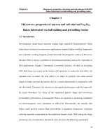
As we have introduced in the previous chapter, the topological Hall effect is the
part of Hall conductance that is dependent on the magnetization profile of the
conductor that a current passes through. In this chapter, we review the important
development in condensed matter that led up to this postulate, and explain the
theory in detail.
Our reviews will be centered on the Hall effects and spintronic effects
like giant magnetoresistance (GMR) and spin transfer torque (STT). The Hall
effects are studied to understand the role it plays in our understanding of condensed matter, and spintronics effects demonstrate how an obscure physical
attribute of the electron could manifest as a phenomenon with important appli-
12
2.1 The Hall Effects
13
Figure 2.1: Overview of physical phenomena related to the topological Hall
effect.
cations.
2.1
The Hall Effects
Hall effects is the term used to describe current flow or voltage induced in the
direction perpendicular the driven current in a planer conductor. There are many
derivatives of the Hall effect, and in this chapter we will review three categories
of Hall effects that are most closely related to the topological Hall effect, and
electron transport phenomena that are closely related to them. Figure 2.1 shows
the overview of the areas that we cover in this review.
The topological Hall effect is eventually derived as the fourth mechanism for explaining Hall conductivity data in a magnetized material with nonuniform magnetization. This review serves to lay the foundation upon which
we derive the THE theory in the next section.
2.2 Hall Effect in Non-Magnetic Material
14
We group the effects that we review into the following three categories:
1. Hall Effects in non-magnetic material
2. Hall Effect in magnetic material (The Anomalous Hall Effect)
3. Spin Hall Effect
2.2
Hall Effect in Non-Magnetic Material
As it is reflected through the shade of red used in Figure 2.1, the Hall effect, quantum Hall effect, and fractional quantum Hall effect are part of the
same measurement of transverse conductivity but occuring at larger and larger
strengths of the applied magnetic field. They are given different names because
of the qualitatively different patterns they display. One can deduce the Hall
effect as the low field limit of the quantum Hall effect, and the quantum Hall
effect as the low field limit of the fractional quantum Hall effect.
To appreciate the roots of the topological Hall effect, we shall take a step
back in history in order to understand the sequence of discoveries that led to
this development.
2.2.1
Hall Effect
The Hall effect originated with Edwin Hall proposing to probe the origin of the
force acting on a current carrying conductor in a magnetic field with an experiment that now bears his name. Back in 1879, the existence of electrical currents
2.2 Hall Effect in Non-Magnetic Material
15
and magnetic fields were well known, with the effect of one on the other captured by Faraday’s law23 . The macroscopic understanding of electrodynamics
had been comprehensively developed by Maxwell23 in the earlier half of the
century, and Hall was about to help usher in a means to inquire further into the
microscopic nature of electromagnetism and matter that would ultimately lead
into the realm of the quantum world.
Hall asked if the force exerted on a current carrying conductor by a magnetic field acted on the current carriers or the conductor itself. It was known
that as the force exerted on the conductor was only dependent on the magnitude on the current flowing through it and not on the material that the conductor
was made of, he reasoned that this hinted that the force was in fact acting on
the current carriers not the conductor itself. Hall hypothesized that if this were
the case, an electromotive force should arise from the charge carriers pushing
against the edge of the conductor. Hall eventually detected the effect in an experiment done on a gold leaf, and found the voltage generated to be proportional
to the applied magnetic field. This was compelling evidence of the hypothesis.
At a time before the existence of the electron was known, the validation of
Hall’s hypothesis was a revolutionary step in our understanding of materials.
The Hall effect provided an insight into the material that it propagates
through. Subsequently, extensive studies of the Hall effect was carried out on a
whole suite of conductors, and the proportionality constant between the transverse voltage and the applied magnetic field, the Hall coefficient, was found to
correlated with the number of valence electrons in most materials (Figure 2.2).