Least squares symbol detection for multi antenna fh mfsk systems in the presence of follower jamming
Bạn đang xem bản rút gọn của tài liệu. Xem và tải ngay bản đầy đủ của tài liệu tại đây (630.83 KB, 59 trang )
LEAST SQUARES SYMBOL DETECTION FOR MULTI
ANTENNA SLOW FHSS/MFSK SYSTEMS IN THE
PRESENCE OF FOLLOWER JAMMING
ALAGUNARAYANAN NARAYANAN
NATIONAL UNIVERSITY OF SINGAPORE
2011
LEAST SQUARES SYMBOL DETECTION FOR MULTI
ANTENNA SLOW FHSS/MFSK SYSTEMS IN THE
PRESENCE OF FOLLOWER JAMMING
ALAGUNARAYANAN NARAYANAN
(B.E., ANNA University)
A THESIS SUBMITTED
FOR THE DEGREE OF MASTER OF ENGINEERING
DEPARTMENT OF ELECTRICAL AND COMPUTER
ENGINEERING
NATIONAL UNIVERSITY OF SINGAPORE
2011
ACKNOWLEDGEMENTS
First of all, I am grateful to God for giving me the strength and wisdom to finish this
thesis.
My sincere thanks goes to my supervisor Professor Ko Chi Chung for his excellent
guidance, encouragement and insightful comments throughout the period of my research
work.
I also wish to express my thanks to the staff and students in the communication
laboratory for their assistance and friendship. Finally, I also wish to express my sincere
gratitude to my parents and family, who have always given me unconditional love and
great support.
i
CONTENTS
ACKNOWLEDGEMENTS
i
CONTENTS
ii
SUMMARY
v
LIST OF FIGURES
vi
LIST OF ABBREVIATIONS
vii
LIST OF SYMBOLS
ix
CHAPTER 1
INTRODUCTION
1
1.1
FREQUENCY SHIFT KEYING
1
1.2
FADING
3
1.3
AWGN
6
1.4
JAMMING
6
1.5
INTRODUCTION TO SPREAD SPECTRUM
1.6
1.7
COMMUNICATIONS
7
FREQUENCY HOPPED SPREAD SPECTRUM SYSTEMS
9
1.5.1 SLOW FHSS SYSTEMS
11
1.5.2 FAST FHSS SYSTEMS
11
PERFORMANCE OF FHSS SYSTEMS IN A JAMMING
ENVIRONMENT
12
1.7
RESEARCH OBJECTIVE and CONTRIBUTIONS
13
1.8
STRUCTURE OF THE THESIS
14
ii
CHAPTER 2
FHSS/MFSK SYSTEMS IN THE PRESENCE OF JAMMING
2.1
15
SYSTEM MODEL
15
2.1.1 TRANSMITTED SIGNAL MODEL
15
2.1.2 PARTIAL BAND JAMMING MODEL
16
2.1.3 RECEIVED SIGNAL MODEL
17
2.2
VECTOR REPRESENTATION
19
2.3
SUMMARY
20
CHAPTER 3
LEAST SQUARES BASED SYMBOL DETECTION SCHEME
21
3.1
LS BASED SYMBOL DETECTION SCHEME
21
3.2
THEORITICAL ANALYSIS OF THE PROPOSED SCHEME
23
3.3
SUMMARY
28
CHAPTER 4
PERFORMANCE OF LS BASED SYMBOL DETECTION SCHEME
29
4.1
SIMULATIONS
29
4.2
SUMMARY
35
CHAPTER 5
CONCLUSIONS AND PROPOSALS FOR FUTURE RESEARCH
36
5.1
CONCLUSION
36
5.2
FUTURE WORK
36
BIBILOGRAPHY
38
iii
APPENDIX-I
43
LIST OF PUBLICATIONS
47
iv
SUMMARY
The focus of this thesis is the performance of frequency hopped M-ary frequency
shift keying (MFSK) systems in the presence of follower partial band jamming (PBJN)
over flat fading channels. Thermal and other wideband Gaussian noises have been
modeled as additive white Gaussian noise (AWGN) at the receiver.
Follower partial band jamming is a strong threat to the symbol error rate (SER)
performance of FHSS systems. In order to overcome the effects of follower PBJN and
carry out symbol detection in slow FHSS/MFSK systems over quasi-static flat fading
channels, a least squares (LS) based method is proposed in this thesis. Specifically, using
the principle of Least squares, the complex gain factor between the two jamming
components is estimated. This estimate is then used to remove the jamming signal during
the symbol detection process.
The effect of AWGN on the channel estimation and symbol detection are theoretically
analyzed. The symbol error rate performances of the proposed algorithm are compared
with that of traditional maximum likelihood (ML) algorithm and the scheme proposed in
[13]. The proposed algorithm is found to outperform the other algorithms, when signal to
noise ratio (SNR) is greater than about 20dB.
v
LIST OF FIGURES
Fig. 1.1
An example of Binary FSK
3
Fig. 1.2
Block diagram of frequency hoped spread spectrum transmitter
9
Fig. 1.3
Block diagram of frequency hopped spread spectrum receiver
Fig. 4.1
Performance of various schemes against SNR for 0dB SJR, BFSK,
and four samples per symbol
30
Fig. 4.2
Performance of various schemes against SNR for 0 dB SJR, 4-FSK
and four samples per symbol
31
Fig. 4.3
Performance of various schemes against SNR for 0 dB SJR, 8-FSK
and eight samples per symbol
31
Fig. 4.4
Performance of various schemes against SJR for 30dB SNR, 8-FSK
and twelve samples per symbol
32
Fig. 4.5
Performance of the proposed LS based scheme with various number
of samples per symbol for 0 dB SJR and 8FSK
32
Fig. 4.6
Performance of the proposed LS based scheme with various number
of samples per symbol at 0 dB SJR and 16 FSK
33
Fig. 4.7
Plot of Mean percentage of absolute error between theoretical
and simulated values of x against SNR, with BFSK, -10 dB SJR and
four samples per symbol
34
Fig. 4.8
Performance of the theoretical and simulated SER of the proposed
scheme for BFSK,-10dB SJR and four samples per symbol
10
35
vi
LIST OF ABBREVIATIONS
AFSK
Audio Frequency Shift Keying
AR
Auto Regressive
ARMA
Auto Regressive Moving Average
AWGN
Additive White Gaussian Noise
BER
Bit Error Rate
CDMA
Code Division Multiple Access
DS
Direct Sequence
DSSS
Direct Sequence Spread Spectrum
FH
Frequency Hopping
FHSS
Frequency Hopped Spread Spectrum
FSK
Frequency Shift Keying
GMSK
Gaussian Minimum Shift Keying
GSM
Global System for Mobile communication
i.i.d
independent and identically distributed
ISI
Inter Symbol Interference
LS
Least Squares
MAI
Multiple Access Interference
MFSK
M-ary Frequency Shift Keying
ML
Maximum Likelihood
vii
MSK
Minimum Shift Keying
MTJ
Multi Tone Jammer
OFDM
Orthogonal Frequency Division Multiplexing
PBJN
Partial Band Jamming Noise
PN
Pseudo noise
PSD
Power Spectral Density
SER
Symbol Error Rate
SJR
Signal to Jamming Power Ratio
SNR
Signal to Noise Power Ratio
SS
Spread Spectrum
VSM
Vector Similarity Metric
viii
LIST OF SYMBOLS
l
phase shift and attenuation for the desired signal, which is received in the
lth antenna
l
phase shift and attenuation for the jamming signal, which is received in
the lth antenna
d
data symbol
d
estimated data symbol
f
frequency of hopping
fd
frequency spacing between two adjacent MFSK tones
h
positive integer
n j t
baseband equivalent band limited signal
N
sampling rate
Pe
theoretical bit error rate
T
duration of one information bit
Tc
chip duration
Ts
sampling period
Time interval
d
cost function
u
pilot symbol
vl
jamming components of the signal received in the lth antenna
ix
w n
added white Gaussian noise
W
bandwidth
x
CHAPTER 1
INTRODUCTION
1.1 FREQUENCY SHIFT KEYING
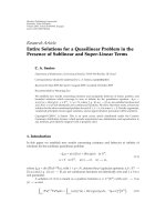
Frequency shift keying (FSK) is a frequency modulation scheme in which digital
information is transmitted through changing the frequency of a carrier wave. M-ary
frequency shift keying (MFSK) is a variation of FSK that uses more than two
frequencies. MFSK is a form of M-ary orthogonal modulation, where each symbol
consists of one element from an alphabet of orthogonal waveforms. M , the size of
the alphabet is usually a power of two, so that each symbol has log 2 M bits. An
example of Binary FSK is shown in fig. 1.1.
Minimum Shift keying (MSK) and audio frequency shift keying (AFSK) are two
other forms of FSK. MSK is a particular form of coherent FSK, and it has better
spectrum usage when compared to FSK. In MSK, the waveforms that are used to
represent the bits 0 and 1 will differ from each other by exactly half a carrier period.
This is the smallest FSK modulation index that can be chosen such that the
waveforms for 0 and 1 are orthogonal. Another form of MSK called Gaussian
minimum shift keying (GMSK), is used in the global system for mobile
communication (GSM) phone standard [30].
1
In Audio frequency-shift keying (AFSK) modulation technique, digital data is
represented by changes in the frequency (pitch) of an audio tone, yielding a signal
that has been encoded suitably for transmission via radio or telephone. Normally, the
transmitted audio shuffles between two tones: "mark" and “space", representing
a binary one and a binary zero respectively. In AFSK, modulation is done at baseband
frequencies. This is the difference between regular frequency-shift keying methods
and AFSK.
Even though Phase Shift Keying (PSK) modulation gives better performance than
FSK in an additive white Gaussian noise (AWGN) channel, it is difficult to maintain
phase coherence in the synthesis of the frequencies used in the hopping pattern.
Therefore, FSK modulation with non coherent detection is used in frequency hopped
spread spectrum (FHSS) systems [2].
2
1
0
1
0
1
Data
Carrier
Modulated signal
Figure 1.1 An example of Binary FSK
1.2 FADING
It is the deviation that a carrier modulated communication signal experiences when
it travels through certain propagation media. In general, fading tends to vary with
time, geographical position and radio frequency, and it can be modelled as a random
process. A channel that experiences fading is called as a fading channel. The two
main reasons for fading in wireless systems are multipath propagation (referred to as
3
multipath fading) and shadowing from obstacles affecting the wave propagation
(referred to as shadow fading).
Multiple paths, in which a signal can traverse, are created by reflectors present in
the environment surrounding the transmitter and receiver. Multipath propagation
results in the superposition of multiple copies of the transmitted signal at the receiver.
While travelling from the source to the receiver, each copy of the signal will be
experiencing differences in terms of attenuation, delay and phase shift, which will
lead to constructive and destructive interferences at the receiver end. This can cause
amplification or attenuation of the signal power at the receiver. Strong destructive
interference (also known as deep fades) can cause temporary failure of
communication due to a severe drop in the channel signal to noise ratio. The effects
of fading can be overcome by using transmit diversity where the signal travels over
different channels that experience independent fading and then coherently combining
them at the receiver. Now, the probability of experiencing a fade in this channel is
proportional to the probability that all the component channels simultaneously
experience a fade.
Different types of fading are discussed below.
Slow fading – It arises when the coherence time of the channel is large when
compared to the delay constraint of the channel. In this type of fading, the
amplitude and phase variations imposed by the channel can be considered as
constant with respect to the symbol period. Slow fading can be caused when
there is a large obstruction such as a hill or large building, obscuring the main
4
signal path between the transmitter and the receiver. Log normal
distribution is often used to model the amplitude change that is caused by
shadowing [30].
Fast Fading – This occurs when the coherence time of the channel is small
compared to the delay constraint of the channel. In this type of fading, the
amplitude and phase variations imposed by the channel vary considerably
with respect to the symbol period. In a fast-fading channel, the transmitter
may use time diversity to take advantage of the variations in the channel
conditions, and thereby increase the robustness of the communication to a
temporary deep fade. A deep fade may temporarily erase some of the
information that was transmitted. By using an error-correcting code coupled
with successfully transmitted bits during other time instances (interleaving),
the erased bits can be recovered [30].
Flat fading – In this type of fading, the coherence bandwidth of the channel is
larger than the bandwidth of the signal. With flat fading all frequency
components will be affected in the same way.
Frequency selective fading – When the coherence bandwidth of the channel
is smaller than the bandwidth of the signal, frequency selective fading occurs.
It is highly improbable that all parts of the signal will be simultaneously
affected by a deep fade because different frequency components of the signal
will be affected independently. Frequency selective fading channels are
dispersive resulting delay spreads in the received signal. As a result, the
transmitted symbols that are adjacent in time interfere with each other. In such
5
channels equalizers can be used to compensate for the effects of the inter
symbol interference (ISI). Modulation schemes such as orthogonal frequency
division
multiplexing
(OFDM) and code
division
multiple
access
(CDMA) use frequency diversity to provide robustness to frequency selective
fading. In OFDM, the wideband signal is divided into many narrowband
modulated subcarriers with each of them being exposed to flat fading rather
than frequency selective fading [32]. CDMA uses the Rake receiver to deal
with each echo separately [30].
1.3 AWGN
In additive white Gaussian noise model, the only impairment to proper
communication is the linear addition of wideband noise with a constant spectral
density and a Gaussian distribution of amplitude. It produces simple and tractable
mathematical models which are useful for gaining insight into the underlying
behavior of the system. Thermal vibrations of atoms in conductors, shot noise, black
body radiation from the earth and other warm objects are the main sources for
wideband Gaussian noise. Background noise of the channel under study is normally
represented using AWGN.
6
1.4 JAMMING
Jamming refers to the deliberate transmission of signals that disrupt
communications, by decreasing the signal to noise ratio at the receiver. Generally, the
jammer sends out a signal at the same frequency as the transmitter and causes
interference to the received signal. The purpose of jamming is to block out the
reception of transmitted signals. Jamming models considered in frequency hopped
spread spectrum (FHSS) systems include partial band multi tone jamming and partial
band Gaussian noise jamming [31]. A follower jammer has the capability to
determine which portion of the spread spectrum bandwidth is being used during some
time interval , and transmits its jamming signal in that portion of the spectrum.
1.5 INTRODUCTION TO SPREAD SPECTRUM
COMMUNICATIONS
In this technique, a communication signal is transmitted in a bandwidth which is
significantly larger than the original frequency content of the signal. The main feature
of this technique is that it decreases the probability of interference to other receivers
while maintaining the privacy. Spread Spectrum generally uses a sequential noise like
signal structure to spread the narrowband information signal over a relatively
wideband of frequencies. At the receiver, the received signal is given to a correlator
to retrieve the original information signal.
7
Major features of spread spectrum communication are
Resistance to jamming (interference) - The transmitted signal will have an
element of pseudo-randomness (unpredictability) associated with it. This
randomness will be known only to the intended receiver and not to the jammer.
As a result, the jammer will transmit an interfering signal without the
knowledge of the pseudo random pattern. This reduces the vulnerability of the
transmitted signal to jamming.
Resistance to fading- Since spread spectrum signals occupy high bandwidth it
is unlikely that the signal will encounter multipath fading over its whole
bandwidth.
Multiple access capability- Multiple users can transmit simultaneously on the
same frequency (range) as long as they use different spreading codes.
The different types of spread spectrum communications are
1. Direct Sequence (DS) – A sine wave is pseudo randomly phase modulated
with a string of pseudo noise code symbols called chips. The duration of the
chip is shorter than that of the information bit.
2. Frequency hopping (FH) - The carrier frequency is pseudo randomly
changed over a wide range of frequency for transmitting radio signals. A
detailed description of frequency hopping system is given in the next section.
3. Time hopping – In this technique, the carrier is turned on and off by a pseudo
random sequence.
8
4. Chirp Spread – Here, wideband frequency modulated chirp pulses are used
to encode information. A chirp is a sinusoidal signal whose frequency
increases or decreased over a certain amount of time.
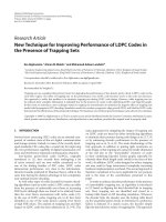
1.6 FREQUENCY HOPPED SPREAD SPECTRUM
SYSTEMS
In this system, each carrier frequency is chosen from a set of 2h (where h is a
positive integer) frequencies that are placed over the width of the available data
modulation spectrum. The pseudo-random code is used to control the sequence of
carrier frequencies. A block diagram of a frequency hopped spread spectrum system
transmitter and receiver are given in fig. 1.2 and 1.3.
Figure 1.2 Block diagram of frequency hopped spread spectrum transmitter
9
Figure 1.3 Block diagram of frequency hopped spread spectrum receiver
Normally binary or M-ary FSK mosulation schemes are used in FHSS. Based on
the symbol transmitted , any one of the M frequencies will be used. The output signal
from the modulator will be translated in frequency by an amount that is determined
by the pseudo noise (PN) sequence, which in turn , is used to selsct a frequency that
is synthesized by the frequency synthesizer. The frequency translated signal is mixed
with the output from the FSK modulator and transmitted. If the PN generator output
has m bits then 2 1 frequency translations are possible.
m
In the receiver , an identical PN generator, that is synchronised with the received
signal, is used to control the output of the frequency synthesizer [19]. By mixing the
synthesizer output with the received signal, the frequency translation introduced at the
transmitter can be removed. The resultant signal is demodulated by means of an FSK
10
demodulator. A signal for maintaining synchronism of the PN generator with the
frequency translated received signal is usually extracted from the received signal.
FHSS systems are mainly used in miltary communication [3], wireless personal
communications [20] and satellite communications [21-23]. Two different types of
frequency hopped spread spectrum systems are discussed below.
1.6.1 SLOW FHSS SYSTEMS
When MFSK data modulation is used with FHSS systems, the data modulator
output is one of the 2h tones, each lasting hT seconds, where T is the duration of the
information bit. Each of these tones will be orthogonal with respect to the other tones.
Hence, the frequency spacing between two tones should be at least
1
. Assume that,
hT
in each Tc (chip duration) seconds the modulated data output is transmitted in a new
frequency by the frequency hop modulator. When Tc hT , the FHSS system is called
a slow frequency hopping system.
1.6.2 FAST FHSS SYSTEMS
In fast FHSS systems, the hopping frequency band changes many times per
symbol. That is Tc hT . A major advantage of fast FHSS systems is that frequency
11
diversity gain can be achieved in each transmitted symbol, which is particularly
beneficial in a partial jamming environment.
1.7 PERFORMANCE OF FHSS SYSTEMS IN A
JAMMING ENVIRONMENT
FHSS systems are known to be robust against interference. However, their
performance will be severely affected by multi tone jamming (MTJ) and partial band
jamming. Among the two, MTJ can cause more damage to the FHSS signal. In partial
band jamming, the frequency that is currently assigned to the receiver is measured by
the jammer and then a jamming signal is transmitted in the frequency slot used. The
jamming signal will be sent as soon as possible, once the current frequency slot is
determined [4].
Fast frequency hopping may be seen as a viable solution to overcome the
detrimental effects of partial band jamming, because of the fact that hopping
frequency changes at a very high rate, making it difficult for the jammer to find out
the current frequency slot used. But when fast frequency hopping is used the
synchronization requirements will become more stringent as hopping rate is increased
and it may be impossible to decrease the dwell interval of the hop. Due to such
practical limitations fast hopping is difficult to be implemented in some applications
and scenarios. The effect of the jammer causes the interference component in the
received signal to be very high. So, symbol detection at the receiver end gets complex.
Many anti-jamming algorithms have been proposed for slow FHSS system to
reduce the effect of jamming. But the focus of most of these algorithms is the
12
elimination of partial band jamming [5-11], with the problem of follower jamming
addressed to a smaller extent in [12-13] and [24]. In [12], an antenna array using the
sample matrix inversion algorithm is exploited to separate the desired signal and the
jamming signal. But, in this case the antennas have been assumed to be having equal
gains. These assumptions will not hold good in a quasi static flat fading channel.
The technique proposed in [24] performs better in a jamming dominant scenario.
But in this technique, the received jamming signals are treated as deterministic
quantities to be estimated. So this algorithm will produce less accurate jamming
estimates at lower jamming power regions. This causes deterioration in the
performance of the algorithm.
Even though vector similarity based symbol detection scheme proposed in [1]
gives good symbol detection performance in the presence of follower jamming in a
quasi static flat fading channel, it assumes that the receiver has complete knowledge
about the channel parameters. This places a restraint on the system.
1.8 RESEARCH OBJECTIVE and CONTRIBUTION
Least squares (LS) method is a standard way of estimating the unknown
parameters from the received data set. In this thesis, we investigate how a least
squares based approach can be formulated for carrying out symbol detection in the
presence of jamming and AWGN in FHSS communication systems. Specifically, the
proposed approach uses a two element array to reject single follower jamming signal
interference and carry out symbol detection in slow FHSS/MFSK systems over quasi
static flat fading channels. Using the principle of Least squares, the complex gain
13