CCNA Lab - Solution Rev1.0 Basic IS-IS
Bạn đang xem bản rút gọn của tài liệu. Xem và tải ngay bản đầy đủ của tài liệu tại đây (294.32 KB, 20 trang )
ieMentor CCIE™ Service Provider Workbook v1.0
|
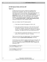
Lab4 Solutions: Basic IS-IS
RR
10.1.1.254
10.1.1.2
10.1.1.3
PE2
PE3
ISIS LEVEL 2 ONLY
ISI
S
LE
VE
L1
VL
ON
AN
LY
21
10.1.1.1
F0/1
Y
NL
1O
L
VE
31
LE
S
I
AN
L
IS
V
PE1
10.1.1.100
ISIS LEVEL 2 ONLY
Serial0/0.101 multipoint
ASBR1
AS100
Serial0/2
Task 4.1:
Task 4.2:
♦ Configure IS-IS between RR1, PE2, and PE3
♦ IS-IS AREA NET 48.0000
♦ IS-IS RR1 AREA NET 48.0000.0254.0254
♦ IS-IS Level 1 in RR1: Configure IS-IS Level 1 only for both
interfaces by using a single command.
The default level of IS-IS is both Level 1 and Level 2. In order to
specify Level 1 only, manual configuration needs to be entered. To
limit it to one command, configure is-type level-1 under the IS-IS
router process. It will automatically activate Level 1 on all
interfaces that have IS-IS configuration.
1
This product is individually licensed.
Copyright® 2005 ieMentor .
ieMentor CCIE™ Service Provider Workbook v1.0
|
Lab4 Solutions: Basic IS-IS
♦ RR1 should advertise VLAN20 and VLAN30, including the
Loopback in Level 1.
RR1
interface Ethernet0/0.20
description to PE2 -VLAN
encapsulation dot1Q 20
ip address 172.16.20.254
ip router isis
!
interface Ethernet0/0.30
description to PE3 -VLAN
encapsulation dot1Q 30
ip address 172.16.30.254
ip router isis
!
router isis
net 48.0000.0254.0254.00
is-type level-1
20
255.255.255.0
30
255.255.255.0
♦ Apply best practices to advertise Loopbacks under IS-IS.
As an option, you may use ip roter isis as shown in the above
output. However, the best practice is to use passive-interface
Loopback0 to advertise a Loopback into IS-IS.
interface Loopback0
ip address 10.1.1.254 255.255.255.255
!
router isis
net 48.0000.0254.0254.00
is-type level-1
passive-interface Loopback0
♦ Configure RR1 such that all changes in IS-IS get sent to logging
console.
router isis
net 48.0000.0254.0254.00
is-type level-1
area-password iementor
log-adjacency-changes all
passive-interface Loopback0
Info NET ID’s Swap for a reason please read questions cerfully.
♦ PE2 IS-IS AREA NET 48.0000.0001.0001.00
2
This product is individually licensed.
Copyright® 2005 ieMentor .
ieMentor CCIE™ Service Provider Workbook v1.0
|
Lab4 Solutions: Basic IS-IS
♦ PE3 IS-IS AREA NET 48.0000.0002.0002.00
PE2
interface Loopback0
ip address 10.1.1.2 255.255.255.255
!
router isis
net 48.0000.0001.0001.00
log-adjacency-changes all
passive-interface Loopback0
PE3
interface Loopback0
ip address 10.1.1.3 255.255.255.255
!
router isis
net 48.0000.0003.0003.00
log-adjacency-changes all
passive-interface Loopback0
At this point, you should be able to receive IS-IS adjacencies.
Task 4.3:
♦ Configure VLAN21 and VLAN31 on PE1 such that only Level 1
updates are exchanged from PE2 and PE3.
This task is asking to configure IS-IS level 1 per interface.
PE1
interface FastEthernet0/0
description to PE3 VLAN31
ip address 172.16.13.1 255.255.255.0
ip router isis
speed 100
full-duplex
isis circuit-type level-1
!
interface FastEthernet0/1
description to PE2 VLAN21
ip address 172.16.12.1 255.255.255.0
ip router isis
speed 100
full-duplex
isis circuit-type level-1
!
3
This product is individually licensed.
Copyright® 2005 ieMentor .
ieMentor CCIE™ Service Provider Workbook v1.0
|
Lab4 Solutions: Basic IS-IS
router isis
net 48.0000.0002.0002.00
is-type level-1
log-adjacency-changes all
♦ Configure PE1 to have the ability to communicate mutually with
Level 1 and Level 2.
Under the IS-IS router process, enter the is-type level-1-2
command. It will not show up in the config output because it is the
default.
♦ At this stage, make sure that no Level 2 gets passed to PE2 and
PE3.
Note that this task is not asking you to configure Level 1 and 2 per
interface.
♦ Make sure you can ping 10.1.1.254 (RR1), 10.1.1.2 (PE2), and
10.1.1.3 (PE3) from PE1.
RR1-RACK1#sho isis neighbors
System Id
PE2-RACK1
PE3-RACK1
Type Interface IP Address
L1
Et0/0.20 172.16.20.2
L1
Et0/0.30 172.16.30.3
State Holdtime Circuit Id
UP
21
RR1-RACK1.01
UP
8
PE3-RACK1.01
PE2-RACK1#sho isis neighbors
System Id
PE1-RACK1
RR1-RACK1
Type Interface IP Address
L1
Et0/0.21 172.16.12.1
L1
Et0/0.20 172.16.20.254
State Holdtime Circuit Id
UP
22
00
UP
8
RR1-RACK1.01
PE3-RACK1#sho isis neighbors
System Id
PE1-RACK1
RR1-RACK1
Type Interface IP Address
L1
Et0/0.31 172.16.13.1
L1
Et0/0.30 172.16.30.254
State Holdtime Circuit Id
UP
27
PE3-RACK1.02
UP
28
PE3-RACK1.01
RR1-RACK1#sho ip route isis
172.16.0.0/16 is variably subnetted, 7 subnets, 2 masks
i L1
172.16.222.0/24 [115/30] via 172.16.20.2, Ethernet0/0.20
[115/30] via 172.16.30.3, Ethernet0/0.30
i L1
172.16.12.0/24 [115/20] via 172.16.20.2, Ethernet0/0.20
i L1
172.16.13.0/24 [115/20] via 172.16.30.3, Ethernet0/0.30
i L1
172.16.114.2/32 [115/30] via 172.16.20.2, Ethernet0/0.20
[115/30] via 172.16.30.3, Ethernet0/0.30
i L1
172.16.114.0/24 [115/30] via 172.16.20.2, Ethernet0/0.20
[115/30] via 172.16.30.3, Ethernet0/0.30
4
This product is individually licensed.
Copyright® 2005 ieMentor .
ieMentor CCIE™ Service Provider Workbook v1.0
i L1
i L1
i L1
10.0.0.0/32
10.1.1.2
10.1.1.3
10.1.1.1
|
Lab4 Solutions: Basic IS-IS
is subnetted, 5 subnets
[115/10] via 172.16.20.2,
[115/10] via 172.16.30.3,
[115/20] via 172.16.20.2,
[115/20] via 172.16.30.3,
Ethernet0/0.20
Ethernet0/0.30
Ethernet0/0.20
Ethernet0/0.30
PE1-RACK1#ping 10.1.1.254
Type escape sequence to abort.
Sending 5, 100-byte ICMP Echos to 10.1.1.254, timeout is 2 seconds:
!!!!!
Success rate is 100 percent (5/5), round-trip min/avg/max = 4/4/4 ms
PE1-RACK1#ping 10.1.1.2
Type escape sequence to abort.
Sending 5, 100-byte ICMP Echos to 10.1.1.2, timeout is 2 seconds:
!!!!!
Success rate is 100 percent (5/5), round-trip min/avg/max = 1/3/4 ms
PE1-RACK1#ping 10.1.1.3
Type escape sequence to abort.
Sending 5, 100-byte ICMP Echos to 10.1.1.3, timeout is 2 seconds:
!!!!!
Success rate is 100 percent (5/5), round-trip min/avg/max = 1/2/4 ms
Task 4.4:
♦ Establish IS-IS Level 2 adjacencies on the link between PE2 and
PE3 over VLAN123.
♦ Apply best practices to advertise Loopbacks under IS-IS.
PE2
interface Ethernet0/0.123
description to PE3 - VLAN 123
encapsulation dot1Q 123
ip address 172.16.123.2 255.255.255.0
ip router isis
isis circuit-type level-2-only
!
router isis
net 48.0000.0001.0001.00
is-type level-1-2 Å You won’t see this line in your output
passive-interface loopback 0
PE3
interface Ethernet0/0.123
description to PE2 - VLAN 123
encapsulation dot1Q 123
5
This product is individually licensed.
Copyright® 2005 ieMentor .
ieMentor CCIE™ Service Provider Workbook v1.0
|
Lab4 Solutions: Basic IS-IS
ip address 172.16.123.3 255.255.255.0
ip router isis
isis circuit-type level-2-only
!
router isis
net 48.0000.0003.0003.00
log-adjacency-changes all
is-type level-1-2 Å In config you will not see this this is default L1-L2
passive-interface loopback 0
Verify if you’ve established Level 2 adjacencies.
PE2-RACK1#sho isis neighbors
System Id
PE1-RACK1
PE3-RACK1
RR1-RACK1
Type
L1
L2
L1
Interface
Et0/0.21
Et0/0.123
Et0/0.20
IP Address
172.16.12.1
172.16.123.3
172.16.20.254
State
UP
UP
UP
Holdtime
26
7
9
Circuit Id
00
PE3-RACK1.03
RR1-RACK1.01
PE3-RACK1#sho isis neighbors
System Id
PE2-RACK1
PE1-RACK1
RR1-RACK1
Type
L2
L1
L1
Interface
Et0/0.123
Et0/0.31
Et0/0.30
IP Address
172.16.123.2
172.16.13.1
172.16.30.254
State
UP
UP
UP
Holdtime
25
25
25
Circuit Id
PE3-RACK1.03
PE3-RACK1.02
PE3-RACK1.01
♦ Configure PE1 Serial0/0 to ASBR1 Serial 0/2 interface with
frame-relay encapsulation; make sure to use back-to-back serial
cable.
PE1
interface Serial0/0
description to Inter-AS ASBR1
no ip address
encapsulation frame-relay
no keepalive
ASBR2
interface Serial0/2
description to PE1-RACK1 ISIS
encapsulation frame-relay
no keepalive
clock rate 8000000
The concept we are testing here is equivalent to a traditional
frame-relay switch. The tricky part here as is in most service
6
This product is individually licensed.
Copyright® 2005 ieMentor .
ieMentor CCIE™ Service Provider Workbook v1.0
|
Lab4 Solutions: Basic IS-IS
provider production world back to back Frame-Relay is used to
provide multiple services. So what we are testing here is common
practice that you would see in a production network. There is no
requirement to use LMI when the PEs are back to back. This allows
service providers to pass MPLS and non-MPLS traffic by utilizing
sub-interfaces of a single physical interface. This particular task is
testing you knowledge of common problems with IS-IS over framerelay multipoint interface. The default frame relay behavior is to
make a physical interface a multipoint interface as soon as you
apply encapsulation frame-relay. This will be the case with S0/0
and S0/2. In the next section we are going to introduce some
“gotchas” and how to troubleshoot them.
♦ Configure PE1 as sub-interface S0/0.100 multipoint. Use the
DLCI number of your choice on both routers.
This is another tricky question When picking your own DLCIs you
may remember that in real network environments DLCIs are often
locally significant, and having different DLCI’s would not matter.
In this case we use back to back frame relay which requires using
the same DLCI on each side. Also, because this sub-interface is
specified as multipoint you must use frame-relay map to map all
protocols that need to pass.
♦ CORRECTION!!! Configure ASBR1 Serial 0/2 interface to PE1
with encapsulation frame-relay, back-to-back.
♦ On ASBR1, configure using the physical interface instead of a
sub-interface.
ASBR1
interface Serial0/2
description to PE1-RACK1 ISIS
ip address 172.16.222.2 255.255.255.0
encapsulation frame-relay
no keepalive
clock rate 8000000
frame-relay map ip 172.16.222.1 201 broadcast
Å this is required to map
the far end of PE1
ASBR1-RACK1#ping 172.16.222.2
Type escape sequence to abort.
Sending 5, 100-byte ICMP Echos to 172.16.222.2, timeout is 2 seconds:
7
This product is individually licensed.
Copyright® 2005 ieMentor .
ieMentor CCIE™ Service Provider Workbook v1.0
|
Lab4 Solutions: Basic IS-IS
.....
Success rate is 0 percent (0/5)
ASBR1-RACK1(config)#int ser 0/2
ASBR1-RACK1(config-if)#frame-relay map ip 172.16.222.2 201 broadcast
Å
this is required in order to ping your own interface
ASBR1-RACK1#ping 172.16.222.2
Type escape sequence to abort.
Sending 5, 100-byte ICMP Echos to 172.16.222.2, timeout is 2 seconds:
!!!!!
Success rate is 100 percent (5/5), round-trip min/avg/max = 4/5/8 ms
ASBR1-RACK1#
*Mar 1 12:41:13.579: ICMP: echo reply sent, src 172.16.222.2, dst 172.16.222.2
*Mar 1 12:41:13.579: ICMP: echo reply rcvd, src 172.16.222.2, dst 172.16.222.2
*Mar 1 12:41:13.583: ICMP: echo reply sent, src 172.16.222.2, dst 172.16.222.2
♦ Configure all necessary frame-relay parameters to establish
basic IP connectivity from PE1 to ASBR1 such that you do not
depend on Inverse ARP for frame-relay interfaces on PE1 and
ASBR1.
PE1
interface Serial0/0.101 multipoint
description to Inter-AS ASBR1 ISIS
ip address 172.16.222.1 255.255.255.0
ip router isis
frame-relay map ip 172.16.222.1 201 broadcast
frame-relay map ip 172.16.222.2 201 broadcast
no frame-relay inverse-arp
ASBR1
interface Serial0/2
description to PE1-RACK1 ISIS
ip address 172.16.222.2 255.255.255.0
encapsulation frame-relay
no keepalive
clock rate 8000000
frame-relay map ip 172.16.222.1 201 broadcast
frame-relay map ip 172.16.222.2 201 broadcast
no frame-relay inverse-arp
PE1-RACK1#ping 172.16.222.2 Å ASBR1
Type escape sequence to abort.
Sending 5, 100-byte ICMP Echos to 172.16.222.2, timeout is 2 seconds:
!!!!!
Success rate is 100 percent (5/5), round-trip min/avg/max = 1/3/4 ms
8
This product is individually licensed.
Copyright® 2005 ieMentor .
ieMentor CCIE™ Service Provider Workbook v1.0
|
Lab4 Solutions: Basic IS-IS
ASBR1-RACK1#sho frame-relay pvc
PVC Statistics for interface Serial0/2 (Frame Relay DTE)
Active
Inactive
Deleted
Static
Local
0
0
0
1
Switched
0
0
0
0
Unused
0
0
0
0
DLCI = 201, DLCI USAGE = LOCAL, PVC STATUS = STATIC, INTERFACE =
Serial0/2
input pkts 29505
output pkts 54016
in bytes 49499339
out bytes 143592151
dropped pkts 0
in pkts dropped 0
out pkts dropped 0
out bytes dropped 0
in FECN pkts 0
in BECN pkts 0
out FECN pkts 0
out BECN pkts 0
in DE pkts 0
out DE pkts 0
out bcast pkts 48017
out bcast bytes 143214793
5 minute input rate 13000 bits/sec, 0 packets/sec
5 minute output rate 0 bits/sec, 0 packets/sec
pvc create time 12:35:45, last time pvc status changed 12:35:45
♦ Establish Level 2 IS-IS adjacencies link between PE1 and
ASBR1.
♦ Configure all necessary components to establish IS-IS with PE1
over a multipoint interface.
♦ Make sure you can ping PE1 10.1.1.1 Loopback0.
ASBR1
interface Serial0/2
description to PE1-RACK1 ISIS
ip address 172.16.222.2 255.255.255.0
ip router isis
encapsulation frame-relay
no keepalive
clock rate 8000000
isis circuit-type level-2
frame-relay map ip 172.16.222.1 201 broadcast
frame-relay map ip 172.16.222.2 201 broadcast
no frame-relay inverse-arp
PE1
interface Serial0/0.101 multipoint
description to Inter-AS ASBR1 ISIS
ip address 172.16.222.1 255.255.255.0
ip router isis
isis circuit-type level-2
frame-relay map ip 172.16.222.1 201 broadcast
frame-relay map ip 172.16.222.2 201 broadcast
no frame-relay inverse-arp
9
This product is individually licensed.
Copyright® 2005 ieMentor .
ieMentor CCIE™ Service Provider Workbook v1.0
|
Lab4 Solutions: Basic IS-IS
PE1-RACK1#sho isis neighbors
System Id
PE2-RACK1
PE3-RACK1
Type Interface IP Address
L1
Fa0/1
172.16.12.2
L1
Fa0/0
172.16.13.3
State Holdtime Circuit Id
UP
29
02
UP
9
PE3-RACK1.02
ASBR1-RACK1#sho isis neighbors
System Id
PE1-RACK1
Type Interface IP Address
L2
Se0/2
172.16.222.1
State Holdtime Circuit Id
INIT 24
PE1-RACK1.02
Notice the INIT state instead of Up in the output above. Let’s figure
out what’s going on here.
ASBR1-RACK1#sho isis timer Å hidden command
Hello Process
Expiration
Type
|
0.181 (Parent)
|
0.181 L2 Hello (Serial0/2)
|
21.630 Adjacency
Update Process
Expiration
Type
|
1.654 (Parent)
|
1.654 L2 CSNP (Serial0/2)
|
6.642 Ager
|
7.556 L1 CSNP (Serial0/2)
|
10:56.173 (Parent)
|
10:56.173
LSP refresh (L2 0000.1001.1001.00-00)
Å you see
only yourself
|
|
18:17.840 LSP lifetime (L2 0000.1001.1001.00-00)
59:10.454 Dynamic Hostname cleanup
ASBR1-RACK1#debug isis adj-packets
*Mar 1 12:50:56.314: ISIS-Adj: Rec L2 IIH from DLCI
2, cir id 0000.0002.0002.02, length 1500
*Mar 1 12:50:56.671: ISIS-Adj: Encapsulation failed
*Mar 1 12:50:59.572: ISIS-Adj: Encapsulation failed
*Mar 1 12:51:02.681: ISIS-Adj: Encapsulation failed
*Mar 1 12:51:04.432: ISIS-Adj: Rec L2 IIH from DLCI
2, cir id 0000.0002.0002.02, length 1500
201 (Serial0/2), cir type L
for
for
for
201
L2 LAN IIH on Serial0/2
L2 LAN IIH on Serial0/2
L2 LAN IIH on Serial0/2
(Serial0/2), cir type L
As you can see from the above output, there is encapsulation
failure. This means that IS-IS is not establishing adjacencies. It
occurs because ISIS depends on the CLNS protocol which is
currently not mapped in our frame-relay.
PE1-RACK1(config)#int ser 0/0.101
10
This product is individually licensed.
Copyright® 2005 ieMentor .
ieMentor CCIE™ Service Provider Workbook v1.0
|
Lab4 Solutions: Basic IS-IS
PE1-RACK1(config-subif)#frame-relay map clns 201 broadcast
ASBR1-RACK1(config)#int ser 0/2
ASBR1-RACK1(config-if)#frame-relay map clns 201 broadcast
Mar 1 12:53:19.765: %CLNS-5-ADJCHANGE: ISIS: Adjacency to PE1-RACK1
(Serial0/2
Up, new adjacency
ASBR1-RACK1#sho isis timers Å Verify again
Hello Process
Expiration
Type
|
2.222 (Parent)
|
2.222 L2 Hello (Serial0/2)
|
27.929 Adjacency
Update Process
Expiration
Type
|
0.848 (Parent)
|
0.848 L2 CSNP (Serial0/2)
|
2.668 Ager
|
4.519 L2 CSNP (Serial0/2)
|
3:20.765 Dup sysID detect
|
9:49.649 (Parent)
|
9:49.649 LSP lifetime (L2 0000.0254.0254.00-00)
|
9:56.452 LSP lifetime (L2 0000.0001.0001.00-00)
|
10:06.649 LSP lifetime (L2 0000.0003.0003.02-00)
|
11:14.653 LSP lifetime (L2 0000.0254.0254.01-00)
|
11:33.828 LSP refresh (L2 0000.1001.1001.00-00)
|
11:37.366 LSP refresh (L2 0000.1001.1001.01-00)
|
17:20.552 LSP lifetime (L2 0000.0003.0003.00-00)
|
18:18.548 LSP lifetime (L2 0000.0002.0002.00-00)
|
18:20.749 LSP lifetime (L2 0000.1001.1001.00-00)
|
18:20.765 LSP lifetime (L2 0000.1001.1001.01-00)
|
18:21.356 LSP lifetime (L2 0000.0003.0003.01-00)
|
56:06.328 Dynamic Hostname cleanup
ASBR1-RACK1#sho clns neighbors
System Id
PE1-RACK1
Interface
Se0/2
SNPA
DLCI 201
State
Up
Holdtime
20
Type Protocol
L2
IS-IS
ASBR1-RACK1#sho isis neighbors
System Id
PE1-RACK1
Type Interface IP Address
L2
Se0/2
172.16.222.1
State Holdtime Circuit Id
UP
27
ASBR1-RACK1.01
ASBR1-RACK1#sho ip route is
172.16.0.0/16 is variably subnetted, 7 subnets, 2 masks
i L2
172.16.30.0/24 [115/30] via 172.16.222.1, Serial0/2
i L2
172.16.20.0/24 [115/30] via 172.16.222.1, Serial0/2
i L2
172.16.12.0/24 [115/20] via 172.16.222.1, Serial0/2
11
This product is individually licensed.
Copyright® 2005 ieMentor .
ieMentor CCIE™ Service Provider Workbook v1.0
i L2
i
i
i
i
L2
L2
L2
L2
|
Lab4 Solutions: Basic IS-IS
172.16.13.0/24 [115/20] via 172.16.222.1, Serial0/2
10.0.0.0/32 is subnetted, 5 subnets
10.1.1.2 [115/20] via 172.16.222.1, Serial0/2
10.1.1.3 [115/20] via 172.16.222.1, Serial0/2
10.1.1.1 [115/10] via 172.16.222.1, Serial0/2
10.1.1.254 [115/30] via 172.16.222.1, Serial0/2
ASBR1-RACK1#ping 10.1.1.1
Å congrats !!!!
Type escape sequence to abort.
Sending 5, 100-byte ICMP Echos to 10.1.1.1, timeout is 2 seconds:
!!!!!
Success rate is 100 percent (5/5), round-trip min/avg/max = 1/2/4 ms
Task 4.5:
ASBR1-RACK1(config-if)#int ser 0/2
ASBR1-RACK1(config-if)#mtu 9216
*Mar 1 13:08:17.321: %CLNS-5-ADJCHANGE: ISIS: Adjacency to PE1-RACK1 (Serial0/2
) Down, neighbor forgot us
Oh wow, now we broke IS-IS again /
Let’s verify if the MTU took effect.
ASBR1-RACK1#sho interfaces serial 0/2
Serial0/2 is up, line protocol is up
Hardware is PowerQUICC Serial
Description: to PE1-RACK1 ISIS
Internet address is 172.16.222.2/24
MTU 9216 bytes, BW 1544 Kbit, DLY 20000 usec,
reliability 255/255, txload 1/255, rxload 1/255
Encapsulation FRAME-RELAY, loopback not set
Keepalive not set
LMI DLCI 1023 LMI type is CISCO frame relay DTE
ASBR1-RACK1#sho isis neighbors
System Id
PE1-RACK1
Type Interface IP Address
L2
Se0/2
172.16.222.1
State Holdtime Circuit Id
INIT 25
ASBR1-RACK1.01
Hmm, back to INIT again.
♦ You are allowed to make MTU changes on PE1 S0/0 to anything
over 17000, but not under.
PE1-RACK1(config)#int ser 0/0
12
This product is individually licensed.
Copyright® 2005 ieMentor .
ieMentor CCIE™ Service Provider Workbook v1.0
|
Lab4 Solutions: Basic IS-IS
PE1-RACK1(config-if)#mtu 17000
Serial0/0 is up, line protocol is up
Hardware is PowerQUICC Serial
Description: to Inter-AS ASBR1
MTU 17000 bytes, BW 1544 Kbit, DLY 20000 usec,
♦ Do not use the same physical MTU on PE1’s as on ASBR1’s
physical interface.
Basically, you are being asked to use the IS-IS components to
resolve this issue instead of matching the physical MTU on both
sides.
PE1-RACK1#sho clns neighbors
System Id
ASBR1-RACK1
Interface
Se0/0.101
SNPA
DLCI 201
State
Init
Holdtime
25
Type Protocol
L2
IS-IS
ASBR1-RACK1(config)#int ser 0/2
ASBR1-RACK1(config-if)#clns mtu 9216
PE1-RACK1(config)#int ser 0/0.101
PE1-RACK1(config-subif)#clns mtu 9216
*Mar 1 13:34:36.104: %SYS-5-CONFIG_I: Configured from console by console
*Mar 1 13:34:36.641: %CLNS-5-ADJCHANGE: ISIS: Adjacency to ASBR1-RACK1 (Serial0
/0.101) Up, new adjacency
♦ After applying your changes, verify communication between PE1
and ASBR1 and all core routers.
ASBR1-RACK1#sho clns neighbors
System Id
PE1-RACK1
Interface
Se0/2
SNPA
DLCI 201
State
Up
Holdtime
26
Type Protocol
L2
IS-IS
ASBR1-RACK1#sho isis neighbors
System Id
PE1-RACK1
Type Interface IP Address
L2
Se0/2
172.16.222.1
State Holdtime Circuit Id
UP
25
ASBR1-RACK1.01
ASBR1-RACK1#sho ip route isis
172.16.0.0/16 is variably subnetted, 7 subnets, 2 masks
i L2
172.16.30.0/24 [115/30] via 172.16.222.1, Serial0/2
i L2
172.16.20.0/24 [115/30] via 172.16.222.1, Serial0/2
i L2
172.16.12.0/24 [115/20] via 172.16.222.1, Serial0/2
i L2
172.16.13.0/24 [115/20] via 172.16.222.1, Serial0/2
10.0.0.0/32 is subnetted, 5 subnets
13
This product is individually licensed.
Copyright® 2005 ieMentor .
ieMentor CCIE™ Service Provider Workbook v1.0
i
i
i
i
L2
L2
L2
L2
|
Lab4 Solutions: Basic IS-IS
10.1.1.2 [115/20] via 172.16.222.1, Serial0/2
10.1.1.3 [115/20] via 172.16.222.1, Serial0/2
10.1.1.1 [115/10] via 172.16.222.1, Serial0/2
10.1.1.254 [115/30] via 172.16.222.1, Serial0/2
ASBR1-RACK1#debug isis adj-packets
IS-IS Adjacency related packets debugging is on
*Mar 1 13:36:10.075: ISIS-Adj: Rec L2 IIH from DLCI 201 (Serial0/2), cir type L
2, cir id 0000.1001.1001.01, length 9216
*Mar 1 13:36:10.263: ISIS-Adj: Sending L2 LAN IIH on Serial0/2, length 9216
This confirms that IS-IS now using the Jumbo-Frame MTU in the
adjacencies.
Task 4.6:
♦ Configure PE1 such that ASBR1 will have the ability to
communicate with the entire core for future BGP peerings.
ASBR1-RACK1#sho ip route isis
172.16.0.0/16 is variably subnetted, 7 subnets, 2 masks
i L2
172.16.30.0/24 [115/30] via 172.16.222.1, Serial0/2
i L2
172.16.20.0/24 [115/30] via 172.16.222.1, Serial0/2
i L2
172.16.12.0/24 [115/20] via 172.16.222.1, Serial0/2
i L2
172.16.13.0/24 [115/20] via 172.16.222.1, Serial0/2
10.0.0.0/32 is subnetted, 5 subnets
i L2
10.1.1.2 [115/20] via 172.16.222.1, Serial0/2
i L2
10.1.1.3 [115/20] via 172.16.222.1, Serial0/2
i L2
10.1.1.1 [115/10] via 172.16.222.1, Serial0/2
i L2
10.1.1.254 [115/30] via 172.16.222.1, Serial0/2
♦ Configure your core such that Level 2 and Level 1 have mutual
route leaking.
Normally, Level 1 and Level 2 do not exchange routes. You have to
leak them into one another by using the route leaking mechanism
as shown below.
PE1
router isis
net 48.0000.0002.0002.00
log-adjacency-changes all
redistribute isis ip level-2 into level-1 distribute-list 100
passive-interface Loopback0
!
access-list 100 permit ip any any log
Verify to make sure the leak hits the ACL:
14
This product is individually licensed.
Copyright® 2005 ieMentor .
ieMentor CCIE™ Service Provider Workbook v1.0
|
Lab4 Solutions: Basic IS-IS
PE1-RACK1#sho access-lists 100
Extended IP access list 100
10 permit ip any any log (4 matches)
♦ Configure core routers to preserve the new style metric during
redistribution from Level 1 to Level 2. Must use TLV 135.
PE1-RACK1(config-router)#router isis
PE1-RACK1(config-router)#metric-style wide level-1-2
Å TLV 135
PE2-RACK1(config-router)#router isis
PE2-RACK1(config-router)#metric-style wide level-1-2
Å TLV 135
PE3-RACK1(config-router)#router isis
PE3-RACK1(config-router)#metric-style wide level-1-2
Å TLV 135
ASBR1(config-router)#router isis
ASBR1(config-router)#metric-style wide level-1-2
Å TLV 135
Task 4.7:
♦ Configure PE2 such that in case of VLAN20 and VLAN 21 failure
you can still communicate with ASBR1’s Loopback through PE3.
♦ Configure PE3 such that in case of VLAN30 and VLAN31 failure
you can still communicate with ASBR1’s Loopback through PE2.
To meet both requirements, your route leaking configuration on
PE2 must be identical to PE3.
PE2
router isis
net 48.0000.0001.0001.00
area-password iementor
log-adjacency-changes all
redistribute isis ip level-2 into level-1 distribute-list 100
passive-interface Loopback0
!
access-list 100 permit ip any any log
*Mar 1 13:54:19.541: %SEC-6-IPACCESSLOGNP: list 100 permitted 0
172.16.20.0 ->
PE3
15
This product is individually licensed.
Copyright® 2005 ieMentor .
ieMentor CCIE™ Service Provider Workbook v1.0
|
Lab4 Solutions: Basic IS-IS
router isis
net 48.0000.0003.0003.00
log-adjacency-changes all
redistribute isis ip level-2 into level-1 distribute-list 100
passive-interface Loopback0
!
access-list 100 permit ip any any log
*Mar 1 13:56:14.722: %SEC-6-IPACCESSLOGNP: list 100 permitted 0
172.16.30.0 ->
PE3-RACK1#sho access-lists 100
Extended IP access list 100
10 permit ip any any log (4 matches)
Now let’s test it:
PE2-RACK1(config)#interface ethernet 0/0.20
PE2-RACK1(config-subif)#shutdown
PE2-RACK1(config-subif)#interface ethernet 0/0.20
*Mar 1 15:01:10.292: %CLNS-5-ADJCHANGE: ISIS: Adjacency to
0000.0254.0254 (Ethernet0/0.20) Down, interface deleted(non-iih)
PE2-RACK1(config)#interface ethernet 0/0.21
PE2-RACK1(config-subif)#shutdown
*Mar 1 15:01:12.299: %SEC-6-IPACCESSLOGNP: list 100 permitted 0
172.16.30.0 ->
255.255.255.0, 1 packet
*Mar 1 15:01:13.853: %CLNS-5-ADJCHANGE: ISIS: Adjacency to
0000.0002.0002 (Ethernet0/0.21) Down, interface deleted(non-iih)
*Mar 1 15:01:13.873: %LDP-5-NBRCHG: LDP Neighbor 10.1.1.1:0 is DOWN
(Interface not operational)
PE2-RACK1(config-subif)#
*Mar 1 15:01:13.918: %SEC-6-IPACCESSLOGNP: list 100 permitted 0 10.1.1.3
-> 255.255.255.255, 1 packet
PE2-RACK1#sho ip route
isis
| include 10.1.1
i L2
10.1.1.3 [115/10] via 172.16.123.3, Ethernet0/0.123
i L2
10.1.1.1 [115/20] via 172.16.123.3, Ethernet0/0.123
i L2
10.1.1.254 [115/20] via 172.16.123.3, Ethernet0/0.123
As you can see 10.1.1.100 Å is missing from the ISIS table, after you
shutdown Ethernet 0/0.20 and 0/0.21 no longer reachable.
Because ISIS does not support IA Redistribution from IA to Level-2 or
Level-1 in this case this solution can be solved with one method only.
ISIS Level 1 does not support default-information originated concept, and
will ignore default-information originate for all Level-1. This task can
16
This product is individually licensed.
Copyright® 2005 ieMentor .
ieMentor CCIE™ Service Provider Workbook v1.0
|
Lab4 Solutions: Basic IS-IS
tested after you bring link E0/0.20 and E0/0.21 back on line. So for now
lets make 10.1.1.100 reachable from PE2.
1st Step required inject Default-route from PE3 to PE2
PE3-RACK1(config)#router isis
PE3-RACK1(config-router)# default-information originate
Let’s verify
PE2-RACK1#sho ip route | include 0.0.0.0/0
i*L2 0.0.0.0/0 [115/10] via 172.16.123.3, Ethernet0/0.123
Let’s test again
PE2-RACK1#traceroute 10.1.1.100
Type escape sequence to abort.
Tracing the route to 10.1.1.100
1 172.16.123.3 4 msec 4 msec 4 msec
2
*
* Å Not good /
This represents problem that ASBR1 does not have route for 172.16.123.X
PE3-RACK1# ping 10.1.1.100
Sending 5, 100-byte ICMP Echos to 10.1.1.100, timeout is 2 seconds:
!!!!!
Success rate is 100 percent (5/5), round-trip min/avg/max = 4/4/4 ms
PE3-RACK1#
PE3-RACK1#SHO IP ROute ISis | INclude 10.1.1
i L2
10.1.1.2 [115/10] via 172.16.123.2, Ethernet0/0.123
i L1
10.1.1.1 [115/10] via 172.16.13.1, Ethernet0/0.31
i ia
10.1.1.4 [115/40] via 172.16.13.1, Ethernet0/0.31
i ia
10.1.1.100 [115/20] via 172.16.13.1, Ethernet0/0.31
i L1
10.1.1.254 [115/10] via 172.16.30.254, Ethernet0/0.30
ASBR1-RACK1#SHO IP ROute | include 172.16.12
i L2
172.16.12.0 [115/20] via 172.16.222.1, Serial0/2
ASBR1-RACK1#SHO IP ROute | include 172.16.123
PE1-RACK1(config-router)#router isis
PE1-RACK1(config-router)#default-information originate
ASBR1-RACK1#sho ip route isis | include 0.0.0.0/0
i*L2 0.0.0.0/0 [115/10] via 172.16.222.1, Serial0/2
17
This product is individually licensed.
Copyright® 2005 ieMentor .
ieMentor CCIE™ Service Provider Workbook v1.0
|
Lab4 Solutions: Basic IS-IS
PE2-RACK1#traceroute 10.1.1.100
Type escape sequence to abort.
Tracing the route to 10.1.1.100
1 172.16.123.3 4 msec 0 msec 0 msec
2 172.16.13.1 [MPLS: Label 30 Exp 0] 4 msec 8 msec 4 msec
3 172.16.222.2 8 msec *
4 msec
PE2-RACK1#ping 10.1.1.100
Type escape sequence to abort.
Sending 5, 100-byte ICMP Echos to 10.1.1.100, timeout is 2 seconds:
!!!!!
Success rate is 100 percent (5/5), round-trip min/avg/max = 4/6/8 ms
PE2-RACK1#
PE2-RACK1(config)#int e 0/0.20
PE2-RACK1(config-subif)#no shut
PE2-RACK1(config-subif)#int e 0/0.21
PE2-RACK1(config-subif)#no shut
PE2-RACK1(config-subif)#
PE2-RACK1#sho ip route isis
18.0.0.0/24 is subnetted, 1 subnets
i L1
18.2.2.0 [115/20] via 172.16.12.1, Ethernet0/0.21
3.0.0.0/24 is subnetted, 1 subnets
i L1
3.3.3.0 [115/20] via 172.16.12.1, Ethernet0/0.21
38.0.0.0/24 is subnetted, 1 subnets
i L1
38.2.1.0 [115/20] via 172.16.12.1, Ethernet0/0.21
140.100.0.0/16 is variably subnetted, 3 subnets, 2 masks
i L1
140.100.2.2/32 [115/20] via 172.16.12.1, Ethernet0/0.21
i L1
140.100.1.0/24 [115/20] via 172.16.12.1, Ethernet0/0.21
i L1
140.100.2.0/24 [115/20] via 172.16.12.1, Ethernet0/0.21
i ia
172.16.240.0 [115/40] via 172.16.12.1, Ethernet0/0.21
i ia
172.16.222.0 [115/20] via 172.16.12.1, Ethernet0/0.21
i L1
172.16.30.0 [115/20] via 172.16.20.254, Ethernet0/0.20
i L1
172.16.13.0 [115/20] via 172.16.12.1, Ethernet0/0.21
i ia
172.16.113.0 [115/30] via 172.16.12.1, Ethernet0/0.21
i L1
10.1.1.3 [115/20] via 172.16.20.254, Ethernet0/0.20
i L1
10.1.1.1 [115/10] via 172.16.12.1, Ethernet0/0.21
i ia
10.1.1.4 [115/40] via 172.16.12.1, Ethernet0/0.21
i ia
10.1.1.100 [115/20] via 172.16.12.1, Ethernet0/0.21
i ia
10.1.1.200 [115/30] via 172.16.12.1, Ethernet0/0.21
i L1
10.1.1.254 [115/10] via 172.16.20.254, Ethernet0/0.20
i L1
12.2.1.0 [115/20] via 172.16.12.1, Ethernet0/0.21
[115/20] via 172.16.12.1, Ethernet0/0.21
i*L2 0.0.0.0/0 [115/10] via 172.16.123.3, Ethernet0/0.123
*Mar 1 15:01:16.818: %SEC-6-IPACCESSLOGNP: list 100 permitted 0
172.16.222.0 ->
18
This product is individually licensed.
Copyright® 2005 ieMentor .
ieMentor CCIE™ Service Provider Workbook v1.0
|
Lab4 Solutions: Basic IS-IS
255.255.255.0, 1 packet
*Mar 1 15:01:18.930: %SEC-6-IPACCESSLOGNP: list 100 permitted 0
172.16.13.0 ->
255.255.255.0, 1 packet
Back to Level 1 again.
PE2-RACK1#sho ip route isis
i ia
172.16.240.0 [115/40] via 172.16.12.1, Ethernet0/0.21
i ia
172.16.222.0 [115/20] via 172.16.12.1, Ethernet0/0.21
i L1
172.16.30.0 [115/20] via 172.16.20.254, Ethernet0/0.20
i L1
172.16.13.0 [115/20] via 172.16.12.1, Ethernet0/0.21
i ia
172.16.113.0 [115/30] via 172.16.12.1, Ethernet0/0.21
i ia
172.16.114.0 [115/30] via 172.16.12.1, Ethernet0/0.21
8.0.0.0/24 is subnetted, 1 subnets
i L1
8.2.1.0 [115/20] via 172.16.12.1, Ethernet0/0.21
10.0.0.0/32 is subnetted, 7 subnets
i L1
10.1.1.3 [115/20] via 172.16.20.254, Ethernet0/0.20
i L1
10.1.1.1 [115/10] via 172.16.12.1, Ethernet0/0.21
i ia
10.1.1.4 [115/40] via 172.16.12.1, Ethernet0/0.21
i ia
10.1.1.100 [115/20] via 172.16.12.1, Ethernet0/0.21
i ia
10.1.1.200 [115/30] via 172.16.12.1, Ethernet0/0.21
i L1
10.1.1.254 [115/10] via 172.16.20.254, Ethernet0/0.20
[115/20] via 172.16.12.1, Ethernet0/0.21
i L1 210.112.4.0/24 [115/20] via 172.16.12.1, Ethernet0/0.21
i L1 210.112.3.0/24 [115/20] via 172.16.12.1, Ethernet0/0.21
12.0.0.0/24 is subnetted, 1 subnets
i L1
12.2.1.0 [115/20] via 172.16.12.1, Ethernet0/0.21
i L1 210.112.2.0/24 [115/20] via 172.16.12.1, Ethernet0/0.21
28.0.0.0/24 is subnetted, 1 subnets
i L1
28.3.2.0 [115/20] via 172.16.12.1, Ethernet0/0.21
i L1 210.112.1.0/24 [115/20] via 172.16.12.1, Ethernet0/0.21
i L1 192.168.2.0/24 [115/30] via 172.16.20.254, Ethernet0/0.20
[115/30] via 172.16.12.1, Ethernet0/0.21
i*L2 0.0.0.0/0 [115/10] via 172.16.123.3, Ethernet0/0.123
As you can see even if VLAN20/21 is active default-gateway took
path over ISIS-L2 Å only
Same rules and test applied for PE3.
Task 4.8:
♦ Configure RR1 to allow the router to ignore IS-IS link-state
packets that are received with internal checksum errors rather than
19
This product is individually licensed.
Copyright® 2005 ieMentor .
ieMentor CCIE™ Service Provider Workbook v1.0
|
Lab4 Solutions: Basic IS-IS
purging the link-state packets. Configure to avoid purge and flood
storms in case of bad checksums LSPs arrived on RR1.
RR1-RACK1(config-router)#router isis
RR1-RACK1(config-router)#ignore-lsp-errors
20
This product is individually licensed.
Copyright® 2005 ieMentor .