CCNA Lab - Securing Networks With Cisco Routers And Switches
Bạn đang xem bản rút gọn của tài liệu. Xem và tải ngay bản đầy đủ của tài liệu tại đây (1.67 MB, 214 trang )
SNRS
Securing Networks
with Cisco Routers
and Switches
Version 2.0
Lab Guide
Editorial, Production, and Web Services: 02.06.07
DISCLAIMER WARRANTY: THIS CONTENT IS BEING PROVIDED “AS IS.” CISCO MAKES AND YOU RECEIVE NO WARRANTIES IN
CONNECTION WITH THE CONTENT PROVIDED HEREUNDER, EXPRESS, IMPLIED, STATUTORY OR IN ANY OTHER PROVISION OF
THIS CONTENT OR COMMUNICATION BETWEEN CISCO AND YOU. CISCO SPECIFICALLY DISCLAIMS ALL IMPLIED
WARRANTIES, INCLUDING WARRANTIES OF MERCHANTABILITY, NON-INFRINGEMENT AND FITNESS FOR A PARTICULAR
PURPOSE, OR ARISING FROM A COURSE OF DEALING, USAGE OR TRADE PRACTICE. This learning product may contain early release
content, and while Cisco believes it to be accurate, it falls subject to the disclaimer above.
The PDF files and any printed representation for this material are the property of Cisco Systems, Inc.,
for the sole use by Cisco employees for personal study. The files or printed representations may not be
used in commercial training, and may not be distributed for purposes other than individual self-study.
SNRS
Lab Guide
Overview
This guide presents the instructions and other information concerning the lab activities for this
course. You can find the solutions in the lab activity Answer Key.
Outline
This guide includes these activities:
̈
Lab 1-1: Configure Layer 2 Security
̈
Lab 1-2: Configure DHCP Snooping
̈
Lab 2-1: Configure Cisco Secure ACS as a AAA Server
̈
Lab 2-2: Configure 802.1x Port-Based Authentication
̈
Lab 3-1: Configure Cisco NFP
̈
Lab 4-1: Configure a Site-to-Site VPN Using Pre-Shared Keys
̈
Lab 4-2: Configure a Site-to-Site VPN Using PKI
̈
Lab 4-3: Configure a GRE Tunnel to a Remote Site
̈
Lab 4-4: Configure a DMVPN
̈
Lab 4-5: Configure a Cisco IOS SSL VPN (WebVPN)
̈
Lab 4-6: Configure Cisco Easy VPN Remote Access
̈
Lab 5-1: Configure Cisco IOS Classic Firewall
̈
Lab 5-2: Configure Cisco IOS Application Policy Firewall
̈
Lab 5-3: Configure a Cisco IOS Zone-Based Policy Firewall
̈
Lab 5-4: Configure Cisco IOS Firewall Authentication Proxy on a Cisco Router
̈
Lab 5-5: Configure a Cisco Router with Cisco IOS IPS
The PDF files and any printed representation for this material are the property of Cisco Systems, Inc.,
for the sole use by Cisco employees for personal study. The files or printed representations may not be
used in commercial training, and may not be distributed for purposes other than individual self-study.
Lab 1-1: Configure Layer 2 Security
Complete this lab activity to practice what you learned in the related module.
Activity Objective
In this activity, you will configure Layer 2 security on a Cisco Catalyst switch. After
completing this activity, you will be able to meet these objectives:
̈
Mitigate a CAM table overflow attack using the appropriate Cisco IOS commands
̈
Mitigate a VLAN hopping attack using the appropriate Cisco IOS commands
̈
Prevent STP manipulation using the appropriate Cisco IOS commands
̈
Mitigate a MAC spoofing attack using the appropriate Cisco IOS commands
̈
Defend a PVLAN attack using the appropriate Cisco IOS commands
Visual Objective
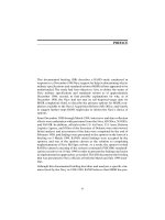
The figure illustrates what you will accomplish in this activity.
Visual Objective for Lab 1-1: Configure
Layer 2 Security
Router
Interface VLAN 1P = .3
FA0/0
Switch
.2
User
10.0.P.0
FA0/1
.2
172.30.P.0
Downstream Switch
Attacker
© 2007 Cisco Systems, Inc. All rights reserved.
SNRS v2.0—3
Required Resources
These are the resources and equipment that are required to complete this activity:
2
̈
Student laptops
̈
Pod routers
̈
Pod switches
Securing Networks with Cisco Routers and Switches (SNRS) v2.0
The PDF files and any printed representation for this material are the property of Cisco Systems, Inc.,
for the sole use by Cisco employees for personal study. The files or printed representations may not be
used in commercial training, and may not be distributed for purposes other than individual self-study.
© 2007 Cisco Systems, Inc.
Command List
The table describes the commands that are used in this activity.
Layer 2 Security Commands
Command
Description
arp timeout seconds
This command is used to configure how long an entry
remains in the ARP cache. To restore the default value,
use the no form of this command.
show port-security
[address] [interface
interface-id]
This command is used to display the port security settings
for an interface or for the switch.
switchport mode access
This command is used to configure a switch port as an
access port only.
switchport port-security
This command enables port security on an interface.
switchport port-security
mac-address [ sticky |
mac-addr ]
This command is used to set a secure MAC address on an
interface or use the sticky option to allow the switch to
learn the first MAC address. Use the no form of this
command to remove a MAC address from the list of secure
MAC addresses.
switchport port-security
maximum max-addr
This command sets the maximum number of secure MAC
addresses for the interface. The range is 1 to 128; the
default is 128.
switchport port-security
violation {shutdown |
restrict | protect}
This command sets the security violation mode for the
interface.
Job Aids
There are no job aids for this activity.
Task 1: Mitigate a CAM Table Overflow Attack
You can mitigate a CAM table overflow attack using the port-security command.
Activity Procedure
Complete these steps:
Step 1
Enter interface configuration mode.
switch(config)# interface FastEthernet 0/2
Step 2
Set the port mode to access.
switch(config-if)# switchport mode access
Step 3
Enable port security on the selected interface.
switch(config-if)# switchport port-security
Step 4
Configure the maximum number of MAC addresses to one.
switch(config-if)# switchport port-security maximum 1
© 2007 Cisco Systems, Inc.
The PDF files and any printed representation for this material are the property of Cisco Systems, Inc.,
for the sole use by Cisco employees for personal study. The files or printed representations may not be
used in commercial training, and may not be distributed for purposes other than individual self-study.
Lab Guide
3
Note
Step 5
The default is one.
Configure the action to take if there is a violation.
switch(config-if)# switchport port-security violation shutdown
Note
Step 6
The default is to shut down.
Configure the MAC address for the port.
switch(config-if)# switchport port-security mac-address
xxxx.xxxx.xxxx
Or
switch(config-if)# switchport port-security mac-address sticky
Step 7
Plug a laptop into Fa0/2 and try to ping the gateway.
C:>ping 10.0.P.2
Activity Verification
You have completed this task when you attain these results:
̈
The output of the show port-security <int> command when port security is configured
using the sticky option will look like this:
switch# show port-security interface FastEthernet 0/2
Port Security
: Enabled
Port Status
: Secure-up
Violation Mode
: Shutdown
Aging Time
: 0 mins
Aging Type
: Absolute
SecureStatic Address Aging : Disabled
Maximum MAC Addresses
: 1
Total MAC Addresses
: 1
Configured MAC Addresses
: 0
Sticky MAC Addresses
: 1
Last Source Address
: 0016.4111.0d49
Security Violation Count
: 0
̈
The output of the show port-security command when port security is configured using the
sticky option will look like this:
switch# show port-security
Secure Port
MaxSecureAddr
CurrentAddr
(Count)
(Count)
SecurityViolation
Security Action
(Count)
--------------------------------------------------------------------------Fa0/2
1
1
0
Shutdown
--------------------------------------------------------------------------Total Addresses in System (excluding one mac per port)
4
Securing Networks with Cisco Routers and Switches (SNRS) v2.0
The PDF files and any printed representation for this material are the property of Cisco Systems, Inc.,
for the sole use by Cisco employees for personal study. The files or printed representations may not be
used in commercial training, and may not be distributed for purposes other than individual self-study.
: 0
© 2007 Cisco Systems, Inc.
Max Addresses limit in System (excluding one mac per port) : 1024
̈
The output of the show port-security address command should resemble the following:
switch# show port-security address
Secure Mac Address Table
------------------------------------------------------------------Vlan
Mac Address
Type
Ports
Remaining Age
(mins)
---11
-----------
----
-----
0016.4111.0d49
SecureSticky
Fa0/2
-------------
------------------------------------------------------------------Total Addresses in System (excluding one mac per port)
: 0
Max Addresses limit in System (excluding one mac per port) : 1024
̈
The output of the show run command should show the following under interface Fa0/2:
!
interface FastEthernet0/2
switchport access vlan 11
switchport mode access
switchport port-security
switchport port-security mac-address sticky
switchport port-security mac-address sticky 0016.4111.0d49
!
Task 2: Mitigate a MAC Spoofing attack
You can show that, using the port-security command, you may also mitigate a MAC spoofing
attack.
Activity Procedure
Complete these steps:
Step 1
Enter interface configuration mode.
switch(config)# interface FastEthernet 0/2
Step 2
Configure the maximum number of MAC addresses.
switch(config-if)# switchport port-security maximum 1
Step 3
Configure the action to take if there is a violation.
switch(config-if)# switchport port-security violation shutdown
Step 4
Set the length of time that an entry will stay in the ARP cache to 60 seconds.
switch(config-if)# arp timeout 60
Activity Verification
You have completed this task when you attain these results:
© 2007 Cisco Systems, Inc.
The PDF files and any printed representation for this material are the property of Cisco Systems, Inc.,
for the sole use by Cisco employees for personal study. The files or printed representations may not be
used in commercial training, and may not be distributed for purposes other than individual self-study.
Lab Guide
5
̈
You plug another PC into the port without the correct MAC address, and the port is shut
down.
̈
The output from the show port-security command should be similar to this:
switch# show port-security
Secure Port
MaxSecureAddr
CurrentAddr
(Count)
(Count)
SecurityViolation
Security Action
(Count)
--------------------------------------------------------------------------Fa0/2
1
1
0
Shutdown
--------------------------------------------------------------------------Total Addresses in System (excluding one mac per port)
: 0
Max Addresses limit in System (excluding one mac per port) : 1024
̈
The output from the show port-security interface command should be similar to this:
switch# show port-security interface fa0/2
Port Security
: Enabled
Port Status
: Secure-shutdown
Violation Mode
: Shutdown
Aging Time
: 0 mins
Aging Type
: Absolute
SecureStatic Address Aging : Disabled
Maximum MAC Addresses
: 1
Total MAC Addresses
: 1
Configured MAC Addresses
: 1
Sticky MAC Addresses
: 0
Last Source Address
: 0050.daeb.43d4
Security Violation Count
: 1
̈
The output from the show interface status command should be similar to this:
switch# show interface status
Port
6
Name
Status
Vlan
Fa0/1
notconnect
1
Fa0/2
err-disabled 11
Fa0/3
notconnect
Fa0/4
Fa0/5
Duplex
Speed Type
auto
auto 10/100BaseTX
a-full
a-100 10/100BaseTX
1
auto
auto 10/100BaseTX
notconnect
1
auto
auto 10/100BaseTX
notconnect
1
auto
auto 10/100BaseTX
Securing Networks with Cisco Routers and Switches (SNRS) v2.0
The PDF files and any printed representation for this material are the property of Cisco Systems, Inc.,
for the sole use by Cisco employees for personal study. The files or printed representations may not be
used in commercial training, and may not be distributed for purposes other than individual self-study.
© 2007 Cisco Systems, Inc.
Task 3: Mitigate a VLAN Hopping attack
You can mitigate a VLAN hopping attack by using the switchport mode command.
Activity Procedure
Complete these steps:
Step 1
Enter interface configuration mode.
switch(config)# interface FastEthernet 0/2
Step 2
Limit the port to access only.
switch(config-if)# switchport mode access
Activity Verification
You have completed this task when you attain these results:
̈
The output from the show running-config command shows the following:
!
interface FastEthernet0/2
switchport mode access
Task 4: Mitigate STP Manipulation
You can mitigate an STP manipulation attack using the root guard and bpdu guard
commands.
Activity Procedure
Complete these steps:
Step 1
Enter global configuration mode.
switch# configure terminal
Step 2
Enable BPDU guard by default on all PortFast ports on the switch.
switch(config)# spanning-tree portfast bpduguard default
Step 3
Enter interface configuration mode.
switch(config)# interface FastEthernet 0/3
Step 4
Enable the root guard feature on the interface.
switch(config-if)# spanning-tree guard root
Activity Verification
You have completed this task when you attain these results:
̈
The output of the show spanning-tree command should be similar to this:
witch# show spanning-tree summary totals
Switch is in pvst mode
Root bridge for: VLAN0011
© 2007 Cisco Systems, Inc.
The PDF files and any printed representation for this material are the property of Cisco Systems, Inc.,
for the sole use by Cisco employees for personal study. The files or printed representations may not be
used in commercial training, and may not be distributed for purposes other than individual self-study.
Lab Guide
7
EtherChannel misconfig guard is enabled
Extended system ID
is enabled
Portfast Default
is disabled
PortFast BPDU Guard Default
is enabled
Portfast BPDU Filter Default is disabled
Loopguard Default
is disabled
UplinkFast
is disabled
BackboneFast
is disabled
Pathcost method used
is short
Name
Blocking Listening Learning Forwarding STP Active
---------------------- -------- --------- -------- ---------- ---------1 vlan
0
0
0
2
2
Task 5: Mitigate a PVLAN Attack
You can use ACLs on a router to mitigate PVLAN attacks.
Note
You are using a router or other Layer 3 device to mitigate the PVLAN attack.
Activity Procedure
Complete these steps:
Step 1
Enter global configuration mode.
router# configure terminal
Step 2
Enter interface configuration mode.
router(config)# ip access-list extended pvlan-attack
Step 3
Configure access control elements and exit.
router(config-ext-nacl)# deny ip 172.30.1.0 0.0.0.255
172.30.1.0 0.0.0.255
router(config-ext-nacl)# permit ip any any
router(config-ext-nacl)# exit
Step 4
Enter interface configuration mode.
router(config)# interface FastEthernet 0/0
Step 5
Apply the ACL to the interface.
router(config-if)# ip access-group pvlan-attack in
8
Securing Networks with Cisco Routers and Switches (SNRS) v2.0
The PDF files and any printed representation for this material are the property of Cisco Systems, Inc.,
for the sole use by Cisco employees for personal study. The files or printed representations may not be
used in commercial training, and may not be distributed for purposes other than individual self-study.
© 2007 Cisco Systems, Inc.
Activity Verification
You have completed this task when you attain these results:
̈
You can connect two computers on an isolated port of the same subnet (172.30.P.0) that
you want to protect.
̈
You try to ping from one to the other.
̈
Your attempts should be unsuccessful.
© 2007 Cisco Systems, Inc.
The PDF files and any printed representation for this material are the property of Cisco Systems, Inc.,
for the sole use by Cisco employees for personal study. The files or printed representations may not be
used in commercial training, and may not be distributed for purposes other than individual self-study.
Lab Guide
9
Lab 1-2: Configure DHCP Snooping
Complete this lab activity to practice what you learned in the related module.
Activity Objective
In this activity, you will configure DHCP snooping on a Cisco Catalyst switch. After
completing this activity, you will be able to meet these objectives:
̈
Enable DHCP snooping globally
̈
Apply DHCP snooping to a VLAN
̈
Configure ports as trusted or untrusted
̈
Verify DHCP snooping configuration
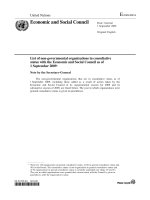
Visual Objective
The figure illustrates what you will accomplish in this activity.
Visual Objective for Lab 1-2: Configure
DHCP Snooping
Switch
Attacker
DHCP Clients
DHCP Server
© 2007 Cisco Systems, Inc. All rights reserved.
SNRS v2.0—4
Required Resources
These are the resources and equipment that are required to complete this activity:
10
̈
Student laptops
̈
Pod switches
̈
Pod routers
Securing Networks with Cisco Routers and Switches (SNRS) v2.0
The PDF files and any printed representation for this material are the property of Cisco Systems, Inc.,
for the sole use by Cisco employees for personal study. The files or printed representations may not be
used in commercial training, and may not be distributed for purposes other than individual self-study.
© 2007 Cisco Systems, Inc.
Command List
The table describes the commands that are used in this activity.
DHCP Snooping Commands
Command
Description
ip dhcp snooping
Globally enables DHCP snooping
ip dhcp snooping vlan
<vlan-id>
Applies DHCP snooping to an active VLAN
ip dhcp snooping trust
Configures a switch port as trusted
show ip dhcp snooping
Displays information on DHCP snooping
Job Aids
There are no job aids for this activity.
Task 1: Globally Enable DHCP Snooping
In this task, you will globally enable DHCP snooping on the switch.
Activity Procedure
Complete these steps:
Step 1
Enter global configuration mode.
router# configure terminal
Step 2
Globally enable DHCP snooping.
switch(config)# ip dhcp snooping
Activity Verification
You have completed this task when you attain these results:
̈
The output of the show ip dhcp snooping command should resemble the following:
switch# show ip dhcp snooping
Switch DHCP snooping is enabled
DHCP snooping is configured on following VLANs:
none
Insertion of option 82 is enabled
Interface
Trusted
Rate limit (pps)
------------------------
-------
----------------
© 2007 Cisco Systems, Inc.
The PDF files and any printed representation for this material are the property of Cisco Systems, Inc.,
for the sole use by Cisco employees for personal study. The files or printed representations may not be
used in commercial training, and may not be distributed for purposes other than individual self-study.
Lab Guide
11
Task 2: Apply DHCP Snooping to an Active VLAN
In this task, you will apply DHCP snooping to an active VLAN.
Activity Procedure
Complete this step:
Step 1
Enable DHCP snooping on a VLAN or range of VLANs.
switch(config)# ip dhcp snooping vlan 11
Activity Verification
You have completed this task when you attain these results:
̈
The output of the show ip dhcp snooping command should resemble the following:.
switch# show ip dhcp snooping
Switch DHCP snooping is enabled
DHCP snooping is configured on following VLANs:
11
Insertion of option 82 is enabled
Interface
Trusted
Rate limit (pps)
------------------------
-------
----------------
Task 3: Configure Trusted Ports
In this task, you will configure a port as trusted if it has a DHCP server connected.
Activity Procedure
Complete these steps:
Step 1
Enter interface configuration mode on the interface facing the DHCP server.
switch(config)# interface FastEthernet 0/2
Step 2
Configure the port as trusted.
switch(config-if)# ip dhcp snooping trust
Activity Verification
You have completed this task when you attain these results:
̈
The output of the show ip dhcp snooping command should resemble this:
switch# show ip dhcp snooping
Switch DHCP snooping is enabled
DHCP snooping is configured on following VLANs:
11
Insertion of option 82 is enabled
12
Interface
Trusted
Rate limit (pps)
------------------------
-------
----------------
FastEthernet0/4
yes
unlimited
Securing Networks with Cisco Routers and Switches (SNRS) v2.0
The PDF files and any printed representation for this material are the property of Cisco Systems, Inc.,
for the sole use by Cisco employees for personal study. The files or printed representations may not be
used in commercial training, and may not be distributed for purposes other than individual self-study.
© 2007 Cisco Systems, Inc.
Task 4: Verify DHCP Snooping
In this task, you will verify the IP DHCP snooping configuration.
Activity Procedure
Complete these steps:
Step 1
Display the DHCP snooping configuration.
switch# show ip dhcp snooping
Step 2
Display only the dynamically configured bindings in the DHCP snooping binding
database.
switch# show ip dhcp snooping binding
Activity Verification
You have completed this task when you attain these results:
̈
The output of the show ip dhcp snooping command should resemble this:
switch# show ip dhcp snooping
Switch DHCP snooping is enabled
DHCP snooping is configured on following VLANs:
11
Insertion of option 82 is enabled
Interface
Trusted
Rate limit (pps)
------------------------
-------
----------------
FastEthernet0/4
yes
unlimited
© 2007 Cisco Systems, Inc.
The PDF files and any printed representation for this material are the property of Cisco Systems, Inc.,
for the sole use by Cisco employees for personal study. The files or printed representations may not be
used in commercial training, and may not be distributed for purposes other than individual self-study.
Lab Guide
13
Lab 2-1: Configure Cisco Secure ACS as a AAA
Server
Complete this lab activity to practice what you learned in the related module.
Activity Objective
In this activity, you will configure a Cisco Secure ACS for Windows to provide AAA services.
After completing this activity, you will be able to meet these objectives:
̈
Install Cisco Secure ACS for Windows
̈
Add a Cisco IOS NAD as a AAA client
̈
Configure administrator interface settings
̈
Install a Cisco Secure ACS certificate
̈
Configure logging and reports
̈
Configure shared profile components
̈
Create a NAP for 802.1x authentication
̈
Define an authentication policy for a NAP
̈
Define an authorization policy for a NAP
Visual Objective
The figure illustrates what you will accomplish in this activity.
Visual Objective for Lab 2-1: Configure
Cisco Secure ACS as a AAA Server
Common Web/FTP Server
(Super Server)
.50
172.26.26.0
.150
Pods 1–5
Pods 6–10
.1
.1
RBB
172.30.P.0
Terminal Server
Router
Router
.3
Switch
Client
.100
.2
.2
.10
Terminal Server
.2
.2
.100
Web
FTP
172.30.Q.0
10.0.P.0
Web/FTP
Cisco Secure
ACS
Student PC
10.0.P.12
Web/FTP
Switch
Cisco Secure
ACS
Student PC
10.0.Q.12
© 2007 Cisco Systems, Inc. All rights reserved.
14
.10
10.0.Q.0
Securing Networks with Cisco Routers and Switches (SNRS) v2.0
The PDF files and any printed representation for this material are the property of Cisco Systems, Inc.,
for the sole use by Cisco employees for personal study. The files or printed representations may not be
used in commercial training, and may not be distributed for purposes other than individual self-study.
Web
FTP
Client
SNRS v2.0—5
© 2007 Cisco Systems, Inc.
Required Resources
These are the resources and equipment that are required to complete this activity:
̈
Intel-based server (laptop or desktop)
̈
Microsoft Windows 2000 Server with SP4
̈
Cisco Secure ACS 4.0
̈
Student laptops
̈
Pod devices
Command List
The table describes the commands that are used in this activity.
Cisco Secure ACS Commands
Command
Description
N/A
—
Job Aids
These job aids are available to help you complete the lab activity.
̈
The job aids shown in some of the tasks are available to help you complete the lab activity.
Task 1: Install Cisco Secure ACS for Windows
In this task, you will install Cisco Secure ACS 4.0 on a Microsoft Windows server machine.
Activity Procedure
Complete these steps:
Step 1
Open the Cisco Secure ACS folder.
Step 2
Double-click Setup.exe. The Cisco Secure ACS 4.0 Setup dialog box opens.
Step 3
Click Accept to acknowledge the terms of the Cisco Secure ACS license agreement.
The Welcome window appears.
Step 4
Click Next in the Welcome window. The Before You Begin dialog box opens.
Step 5
Check all items listed in the Before You Begin window and click Next. The Choose
Destination Location dialog box opens.
Step 6
̈
End-user clients can successfully connect to AAA clients.
̈
This Microsoft Windows server can ping the AAA clients.
̈
Any Cisco IOS AAA clients are running Cisco IOS Release 11.1 or later.
̈
Microsoft Internet Explorer 6 SP1 or Netscape 8.0 is installed.
Click Next to accept the default settings in the Choose Destination Location
window. The Authentication Database Configuration dialog box opens.
© 2007 Cisco Systems, Inc.
The PDF files and any printed representation for this material are the property of Cisco Systems, Inc.,
for the sole use by Cisco employees for personal study. The files or printed representations may not be
used in commercial training, and may not be distributed for purposes other than individual self-study.
Lab Guide
15
Step 7
Choose Check the Cisco Secure ACS database Only and click Next. The files are
installed on the server. The Advanced Options dialog box opens.
Step 8
Leave all of the Advanced Options selections unchecked at this time and click Next.
The Active Service Monitoring dialog box opens.
Step 9
Accept the Active Service Monitoring defaults by clicking Next. The Cisco Secure
ACS Service Initiation dialog box opens.
Step 10
Enter cisco123 as the Cisco database encryption password. Click Next.
Step 11
Accept the default settings within the Cisco Secure ACS Service Initiation window
by clicking Next. Setup then starts the Cisco Secure ACS service. The Setup
Complete dialog box opens.
Step 12
Click Finish.
Activity Verification
You have completed this task when you attain these results:
̈
On the Microsoft Windows server, choose Start > Administrative Tools > Services.
Check that all seven Cisco Secure ACS services are “Started.”
Task 2: Add a Cisco IOS NAD as a AAA Client
In this task, you will configure the Cisco IOS NAD as a AAA client in the Cisco Secure ACS
database.
Activity Procedure
Complete these steps:
Step 1
Click the Network Configuration button in the navigation bar.
Step 2
In the AAA Clients box, click Add Entry. The Add AAA Client window opens.
Step 3
Enter the hostname of your switch as SwP (where P = your pod number) in the AAA
Client Hostname field.
Step 4
Enter an IP address of 10.0.P.3 (where P = your pod number) in the AAA Client IP
Address field. This is the IP address of the switch (NAD) interface that will forward
RADIUS packets to the Cisco Secure ACS.
Step 5
Enter a shared RADIUS key of radiuskey in the Key field.
Step 6
Choose RADIUS (IETF) from the Authenticate Using list.
Step 7
Click Submit + Apply.
Activity Verification
You have completed this task when you attain these results:
̈
16
You can view the new AAA client in the AAA Clients box.
Securing Networks with Cisco Routers and Switches (SNRS) v2.0
The PDF files and any printed representation for this material are the property of Cisco Systems, Inc.,
for the sole use by Cisco employees for personal study. The files or printed representations may not be
used in commercial training, and may not be distributed for purposes other than individual self-study.
© 2007 Cisco Systems, Inc.
Task 3: Configure Administrator Interface Settings
In this task, you will configure the Cisco Secure ACS administrator interface.
Activity Procedure
Complete these steps:
Step 1
Click the Interface Configuration button in the navigation bar. The Interface
Configuration window opens.
Step 2
Choose Advanced Options. The Advanced Options window opens.
Step 3
Enable these advanced options by checking the check boxes in the Advanced
Options list (uncheck any other items that are checked, for this lab only):
̈
Group-Level Shared Network Access Restrictions
̈
Group-Level Network Access Restrictions
̈
Group-Level Downloadable ACLs
̈
Network Access Filtering
Step 4
Click Submit.
Step 5
Choose RADIUS (IETF). The RADIUS (IETF) options window opens.
Step 6
Check these items (uncheck any other items that are checked, for this lab only):
Step 7
̈
[027] Session-Timeout
̈
[029] Termination-Action
̈
[064] Tunnel-Type
̈
[065] Tunnel-Medium-Type
̈
[081] Tunnel-Private-Group-ID
Click Submit.
Activity Verification
You have completed this task when you attain these results:
̈
Review your settings by choosing Interface Configuration > Advanced Options.
Task 4: Add an Administrator
In this task, you will configure the Cisco Secure ACS administrator account.
Activity Procedure
Complete these steps:
Step 1
Click the Administration Control button in the navigation bar. The Administration
Control window opens.
Step 2
Click the Add Administrator button. The Add Administrator window opens.
Step 3
Enter the administrator name admin in the Administrator Name field.
© 2007 Cisco Systems, Inc.
The PDF files and any printed representation for this material are the property of Cisco Systems, Inc.,
for the sole use by Cisco employees for personal study. The files or printed representations may not be
used in commercial training, and may not be distributed for purposes other than individual self-study.
Lab Guide
17
Step 4
Enter the password cisco123 in the Password field.
Step 5
Re-enter the password cisco123 in the Confirm Password field.
Step 6
Scroll down to the Administrator Privileges box and click Grant All.
Step 7
Click Submit.
Activity Verification
You have completed this task when you attain these results:
̈
Review your settings under Administration Control.
Task 5: Install a Cisco Secure ACS Certificate
In this task, you will install the required Cisco Secure ACS certificate.
Activity Procedure
Complete these steps:
18
Step 1
Click the System Configuration button in the navigation bar. The System
Configuration window opens.
Step 2
Click ACS Certificate Setup. The Cisco Secure ACS Certificate Setup window
opens.
Step 3
Choose Install Cisco Secure ACS Certificate. The Install Cisco Secure ACS
Certificate window opens.
Step 4
Choose Read Certificate from File.
Step 5
Enter the full path to the certificate file as c:\certs\server.cer in the Certificate File
field.
Step 6
Enter the full path to the private key file as c:\certs\server.pvk in the Private Key
File field.
Step 7
Enter the private key password 1111 in the Private Key Password field.
Step 8
Click Submit. The Installed Certificate Information window opens, displaying
“OK” on the Validity line. Do not restart the Cisco Secure ACS system as prompted.
Step 9
Click the System Configuration button in the navigation bar. The System
Configuration window opens.
Step 10
Click Cisco Secure ACS Certificate Setup. The Cisco Secure ACS Certificate
Setup window opens.
Step 11
Choose Cisco Secure ACS Certification Authority Setup. The Cisco Secure ACS
Certification Authority Setup window opens.
Step 12
Enter the full path to the CA certificate file as c:\certs\ca.cer in the CA Certificate
File field. A configuration change message is displayed. Do not restart Cisco Secure
ACS as prompted.
Step 13
Click Submit.
Securing Networks with Cisco Routers and Switches (SNRS) v2.0
The PDF files and any printed representation for this material are the property of Cisco Systems, Inc.,
for the sole use by Cisco employees for personal study. The files or printed representations may not be
used in commercial training, and may not be distributed for purposes other than individual self-study.
© 2007 Cisco Systems, Inc.
Step 14
Click the System Configuration button in the navigation bar. The System
Configuration window opens.
Step 15
Click Cisco Secure ACS Certificate Setup. The Cisco Secure ACS Certificate
Setup window opens.
Step 16
Click Edit Certificate Trust List. The Edit Certificate Trust List window opens.
Step 17
Scroll down until you locate the Stress CA.
Step 18
Check the Stress check box.
Step 19
Click Submit.
Step 20
Choose System Configuration > Service Control.
Step 21
Click Restart. A progress bar in the lower-right corner of the window indicates the
status of the restart. When the browser refreshes (blinks), this task is complete.
Activity Verification
You have completed this task when you attain these results:
̈
By choosing System Configuration > Cisco Secure ACS Certificate Setup > Install
Cisco Secure ACS Certificate, you can view your certificate information.
Task 6: Configure Logging and Reports
In this task, you will configure Cisco Secure ACS service logging.
Job Aid
Use the values shown in this table to complete this task.
CSV Failed Attempts
CSV Passed Authentications
Log to CSV Failed Attempts
Report
Logged Attribute
̇
̇
̇
̇
̇
̇
̇
̇
̇
̇
̇
̇
̇
̇
̇
̇
Message-Type
User-Name
Group Name
Caller-ID
Authen-Failure-Code
Author-Failure-Code
Authen-Data
NAS-Port
NAS-IP-Address
AAA Server
Filter Information
Access Device
Network Access Profile Name
Shared RAC
Downloadable ACL
Reason
Log to CSV Passed Authentication
Report
Logged Attribute
̇
̇
̇
̇
̇
̇
̇
̇
̇
̇
̇
̇
̇
Message-Type
User-Name
Group Name
Caller-ID
NAS-Port
NAS-IP-Address
AAA Server
Filter Information
Access Device
Network Access Profile Name
Shared RAC
Downloadable ACL
Reason
© 2007 Cisco Systems, Inc.
The PDF files and any printed representation for this material are the property of Cisco Systems, Inc.,
for the sole use by Cisco employees for personal study. The files or printed representations may not be
used in commercial training, and may not be distributed for purposes other than individual self-study.
Lab Guide
19
Activity Procedure
Complete these steps:
Step 1
Click the System Configuration button in the navigation bar. The System
Configuration window opens.
Step 2
Click Service Control.
Step 3
Scroll down to the Services Log File Configuration section and make these changes:
̈
Set the Level of Detail option to Full.
̈
Set the Generate New File option to When Size Is Greater Than 2048KB.
Step 4
Leave all other parameters at their default settings and click Restart. A progress bar
in the lower-right corner of the window indicates the status of the restart. When the
browser refreshes (blinks), this task is complete.
Step 5
Click the System Configuration button in the navigation bar. The System
Configuration window opens.
Step 6
Click Logging. The Logging Configuration window opens.
Step 7
Click CSV Passed Authentications. The CSV Passed Authentications File
Configuration window opens.
Step 8
Locate the Enable Logging area and check the Log to CSV Passed
Authentications Report check box.
Step 9
Locate the Select Columns to Log area and click the Right Arrow button to move
the NAC-specific attributes listed in the job aid for this task to the Logged Attributes
column.
Step 10
Click Submit.
Step 11
Click CSV Failed Attempts.
Step 12
Repeat Step 9 for CSV Failed Attempts.
Step 13
Click Submit. The system returns you to the Logging Configuration window. The
CSV Passed Authentications and CSV Failed Attempts logging configuration should
now show a check (enabled) in the Use column.
Activity Verification
You have completed this task when you attain these results:
̈
Review your settings by choosing System Configuration > Logging.
Task 7: Configure Global Authentication
In this task, you will enable EAP for 802.1x authentication and set the various EAP session
timeout values.
Note
20
You usually enable all protocols globally so that you can choose a specific protocol from the
protocols later on during the NAP configuration process. You can choose to enable one or
all protocols here. Whatever you select here, will be available for selection when configuring
a NAP.
Securing Networks with Cisco Routers and Switches (SNRS) v2.0
The PDF files and any printed representation for this material are the property of Cisco Systems, Inc.,
for the sole use by Cisco employees for personal study. The files or printed representations may not be
used in commercial training, and may not be distributed for purposes other than individual self-study.
© 2007 Cisco Systems, Inc.
Job Aid
Use the values shown in this table to complete this task.
EAP Configuration
PEAP
Allow EAP-MSCHAPv2
Allow EAP-GTC
Allow Posture Validation
Cisco client initial message:
<empty>
PEAP session timeout (minutes): 120
Enable Fast Reconnect:
EAP-FAST
EAP-FAST Configuration
(see below)
EAP-TLS
Allow EAP-TLS
Choose one or more of the following options:
Certificate SAN comparison
Certificate CN comparison
Certificate Binary comparison
EAP-TLS Session Timeout (minutes):
120
LEAP
Allow LEAP (For Aironet only)
EAP-MD5
Allow EAP-MD5
AP EAP request timeout (seconds):
20
MS-CHAP Configuration
Allow MS-CHAP Version 1 Authentication
Allow MS-CHAP Version 2 Authentication
EAP-FAST Settings
EAP-FAST
Allow EAP-FAST
Active master key TTL:
1 month
Retired master key TTL:
3 month
Tunnel PAC TTL:
1 week
Client Initial Message:
<empty>
Authority ID Info:
cisco
Allow anonymous in-band PAC provisioning
Allow authenticated in-band PAC provisioning
Accept client on authenticated provisioning
Require client certificate for provisioning
Allow Machine Authentication
Machine PAC TTL
1 week
Allow Stateless Session Resume
Authorization PAC TTL 1 hour
© 2007 Cisco Systems, Inc.
The PDF files and any printed representation for this material are the property of Cisco Systems, Inc.,
for the sole use by Cisco employees for personal study. The files or printed representations may not be
used in commercial training, and may not be distributed for purposes other than individual self-study.
Lab Guide
21
Allow inner methods
EAP-GTC
EAP-MSCHAPv2
EAP-TLS
Choose one or more of the following EAP-TLS comparison methods:
Certificate SAN comparison
Certificate CN comparison
Certificate binary comparison
120
EAP-TLS session timeout (minutes):
EAP-FAST master server
Actual EAP-FAST server status:
Master
Note
You will not be authenticating to an external Active Directory server, so machine
authentication is not enabled.
It is recommended that you enable all protocols globally. You will be able to configure specific
protocols for specific NAPs later.
Activity Procedure
Complete these steps:
Step 1
Click the System Configuration button in the navigation bar. The System
Configuration window opens.
Step 2
Choose Global Authentication Setup. The Global Authentication Setup window
opens.
Step 3
Locate the EAP configuration sections.
Step 4
Configure the settings in accordance with the job aid for this task.
Step 5
Set the EAP session timeout values in accordance with the job aid.
Step 6
Click Submit + Restart.
Activity Verification
You have completed this task when you attain these results:
̈
22
Review your settings by choosing System Configuration > Global Authentication Setup.
Securing Networks with Cisco Routers and Switches (SNRS) v2.0
The PDF files and any printed representation for this material are the property of Cisco Systems, Inc.,
for the sole use by Cisco employees for personal study. The files or printed representations may not be
used in commercial training, and may not be distributed for purposes other than individual self-study.
© 2007 Cisco Systems, Inc.
Task 8: Create Groups and Users
In this task, you will configure Cisco Secure ACS groups and users to support 802.1x
authentication.
Job Aid
Use the values shown in this table to complete this task.
Group
Name
Description
1
Corporate
Corporate users
2
Engineering
Engineering users
3
Guests
Guest users
Create Groups
This procedure describes how to create the groups for use with 802.1x.
Activity Procedure
Complete these steps:
Step 1
Click the Group Setup button in the navigation bar.
Step 2
Choose group number 1 from the Group list.
Step 3
Click Rename Group. Enter the group name Corporate in the Group field to
replace the existing name.
Step 4
Click Submit.
Step 5
Repeat Step 2 through Step 4 to create the Engineering and Guest groups.
Create Users
This procedure describes how to create the usernames for use with 802.1x.
Job Aid
Use the values shown in this table to complete this task.
Username
Group
user1
Corporate
eng1
Engineering
guest1
Guest
Activity Procedure
Complete these steps:
Step 1
Click the User Setup button in the navigation bar. The User Setup window opens.
Step 2
Enter the new username user1 in the User field.
Step 3
Click Add/Edit. The User: User1 (New User) window opens.
© 2007 Cisco Systems, Inc.
The PDF files and any printed representation for this material are the property of Cisco Systems, Inc.,
for the sole use by Cisco employees for personal study. The files or printed representations may not be
used in commercial training, and may not be distributed for purposes other than individual self-study.
Lab Guide
23