xúc tác mcm22 trong lọc hóa dầu
Bạn đang xem bản rút gọn của tài liệu. Xem và tải ngay bản đầy đủ của tài liệu tại đây (318.5 KB, 9 trang )
Slovak Society of Chemical Engineering
Institute of Chemical and Environmental Engineering
Slovak University of Technology in Bratislava
PROCEEDINGS
rd
33
International Conference of Slovak Society of Chemical Engineering
Hotel Hutník
Tatranské Matliare, Slovakia
May 22 – 26, 2006
Editors: J. Markoš and V. Štefuca
ISBN 80-227-2409-2
33rd International Conference of SSCHE
May 22–26, 2006, Tatransk´e Matliare, Slovakia
Le-Tu-3, 061p.pdf
MODELING OF ETHYLBENZENE PRODUCTION PROCESS WITH
INTERNAL RECYCLE
Peter Burian **, Marcell Horváth *, Peter Mizsey * and Alois Mészáros **
(**) P. Burian, A. Mészáros
Slovak University of Technology,
Faculty of Chemical and Food Technology,
Radlinského 9, 81237 Bratislava, Slovak Republic
E-Mail:
(*) M. Horváth, P. Mizsey,
Budapest University of Technology and Economics,
Faculty of Chemical Engineering,
Műegyetem rkp. 3-9, H-111 Budapest, Hungary
E-mail:
Keywords: recycle system, dynamic analysis, separation process
Introduction:
Ethylbenzene is a very important industrial substance: it is mainly used as an intermediate in
the production of styrene. Ethylbenzene is also a major component of mixed xylenes used as
solvents in agricultural and home insecticide sprays, rubber and chemical manufacturing, and
household degreasers, paints, adhesives, and rust preventives [1].
The overall dynamics of chemical processing plants with material recycle can be very different
from the dynamics of the individual processing units. Material recycle may dramatically alter the
overall gain and time constants of the plant, and may give rise to oscillatory or instable behaviour,
even when the individual processing units are stable by themselves. In most cases, recycle leads to
positive feedback effects. For example, increasing the concentration of a chemical species in a
process stream will normally increase the amount of this species in the recycle stream, and, thus,
lead to a reinforcement of the original increase. It refers to a self-reinforcing mechanism associated
with the recycle [3,5].
The aim of this paper is to give a comprehensive picture on dynamic behaviour of processes with
internal recycle. The analysis is carried out applying theoretical and simulation experimental tools
on the model of the ethylbenzene production process.
061–1
33rd International Conference of SSCHE
May 22–26, 2006, Tatransk´e Matliare, Slovakia
Le-Tu-3, 061p.pdf
1. Ethylbenzene Production
Ethylbenzene is a clear, colourless liquid with a characteristic sweet, gasoline-like, aromatic
odour. It is a flammable and combustible liquid. Its combustion may produce irritants and toxic
gases. It is exclusively used as an intermediate for the manufacture of styrene. Currently, the
primary source of ethylbenzene is the alkylation of benzene with ethylene [4].
Process Description
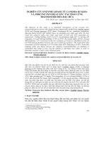
The ethylbenzene process consists of two subsystems (Fig. 1):
•
•
a reactor, where ethylene is reacted with benzene.
a distillation section, where the rest of benzene and polyethylbenzenes are separated from
the reactor effluent to produce ethylbenzene of high purity.
Fig. 1 Ehtylbenzene production system
Benzene is alkylated with ethylene to form ethylbenzene in the reactor in present of AlCl3 catalyst.
Diethylbenzenes, triethylbenzenes and other heavier polyethylbenzenes are also formed. The
benzene feed is heated to reaction temperature.
To maximize ethylbenzene formation, the diethylbenzene is usually transalkylated with benzene to
form more ethylbenzene.
The reactor effluent, a mixture of benzene, ethylbenzene and polyethylbenzenes, flows to a
distillation block. Untreated benzene is recovered in the first distillation column, which is called
benzene column. The benzene from the top of the column is recycled to the reactor. The bottoms
containing ethylbenzene, diethylbenzene and triethylbenzene is fed to the second column called
ethylbenzene column. It separates ethylbenzene from the polyethylbenzenes as a final product. The
ethylbenzene in a high purity (99,9%) is led away from the top of the second column. The mixture
of diethylbenzene and triethylbenzene takes out from the bottom of the second column and it is fed
into the third column. Diethylbenzene from the third, the so-called polyethylbenzene column, is
recycled back to the reactor. [1,2]
061–2
33rd International Conference of SSCHE
May 22–26, 2006, Tatransk´e Matliare, Slovakia
Le-Tu-3, 061p.pdf
2. Dynamic model
The system of the reactor and the first distillation column is studied in the first step.
a. Reactor
Benzene, with flow rate of 327,612 kmol/h and ethylene with flow rate of 121,802 kmol/h is
fed to the reactor (at the temperature of 180 ºC). The temperature in the reactor is 180 ºC and the
pressure is 10 bars. Three exothermic reactions occur in liquid phase, in presence of AlCl3 catalyst.
+
+
+
CH2=CH2
CH2=CH2
CH2=CH2
k1
∆rH1
k-1
k2
∆rH2
k-2
k3
∆rH3
k-3
where ki stands for reaction rate
k i = k 0i e
−
E
RT
The conversion of the benzene in the reactor is approximately 28%. The reactor effluent contains
benzene, ethylbenzene, diethylbenzene and triethylbenzene. This mixture is led out from the bottom
of the reactor.
The model of the process can be derived from the material and energy balance laws.
Material balance:
Benzene:
F1 − ν B ξ V 1V + ν EB ξ V −1V = F3 x B +
d [Vx B ]
dt
(1)
Ethylene:
F2 − ν E ξ V 1V + ν EB ξ V −1V − ν E ξ V 2V + ν DEB ξ V − 2V − ν E ξ V 3V + ν TEB ξ V −3V = F3 x E +
Ethylbenzene:
ν E ξ V 1V − ν EB ξV −1V − ν E ξV 2V + ν DEB ξ V − 2V = F3 x EB +
d [Vx EB ]
dt
Diethylbenzene:
ν E ξ V 2V − ν DEB ξV −2V − ν E ξV 3V + ν TEB ξ V −3V = F3 x DEB +
Triethylbenzene:
ν E ξ V 3V − ν TEB ξV −3V = F3 xTEB +
d [VxTEB ]
dt
d [Vx DEB ]
dt
d [Vx E ]
(2)
dt
(3)
(4)
(5)
061–3
33rd International Conference of SSCHE
May 22–26, 2006, Tatransk´e Matliare, Slovakia
Le-Tu-3, 061p.pdf
Energy balance:
Reactor effluent:
F1c p1T1 + F2 c p 2T2 = F3 c p 3T + Ak [T − Tc ] + ξ V 1V∆ r H 1 + ξ V 2V∆ r H 2 + ξ V 3V∆ r H 3 +
dVc p 3T
dt
(6)
Coolant:
Fc c pc Tc 0 + Ak [T − Tc ] = Fc c pc Tc +
dVc c pc Tc
(7)
dt
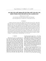
b. First column
The first column (see Fig. 2) is used to separate benzene from the other product components.
The column consists of 12 trays, a reboiler and a condenser. The top-product of the column is
benzene with purity higher than 99%. The other three components leave the first column at the
bottom, and are fed into the second column. The feed is saturated liquid. Equimolal overflow and
constant relative volatility are assumed.
The model of the column is derived from the material balance law.
Condenser:
nv y1 = FD x 0 + n L x 0 +
d [H 0 x 0 ]
dt
1st tray:
n L x 0 + nV y 2 = nV y1 + n L x1 +
y1 = f ( x1 )
d [H 1 x1 ]
dt
ith tray:
n L xi =1 + nV y i +1 = nV y i + n L xi +
y i = f ( xi )
d [H i xi ]
dt
7th (feed) tray:
n L x 6 + nV y8 + FF x F = nV y 7 + n L x 7 +
Fig. 2 Distillation column
y 7 = f (x7 )
kth tray:
(FF
+ n L )x k =1 + nV y k +1 = nV y k + n L x k +
y k = f (x k )
Reboiler:
(FF
+ n L )x n = nV y n +1 + FW xW +
y n +1 = f (x n +1 )
d [H k x k ]
dt
d [H 7 x 7 ]
dt
(15)
(16)
d [H n +1 x n +1 ]
dt
(17)
(18)
061–4
33rd International Conference of SSCHE
May 22–26, 2006, Tatransk´e Matliare, Slovakia
Le-Tu-3, 061p.pdf
List of symbols:
nL – flow rate of liquid phase in column
nV – flow rate of vapour phase in column
FF – fresh feed to column
(flow rate of reactor mixture)
FW – flow rate of bottoms
FD – flow rate of distillate
xi – composition in liquid phase
yi – composition in vapour phase
– flow rate of benzene
– flow rate of ethylene
– flow rate of reactor mixture
– stoichiometric coefficient
– volume of the reactor
– reaction enthalpy
– heat capacity
– temperature of the reactor effluent
– input temperature of the coolant
– output temperature of the coolant
– heat transfer surface
F1
F2
F3
νi
V
∆rHj
cpi
T
TC0
TC
A
A simulation schema, created in MATLAB SIMULINK environment can be seen in Fig. 3.
Fig. 3 Simulation model in Matlab - Simulink environment
3. Simulation results
Simulation experiments, applying input variables step changes to the process, were carried out to
demonstrate the dynamic behaviour of the system. First, process transient behaviour with recycle, as
responses to step-wise changes in inlet benzene flow rate (change of + 7%), ethylene flow rate (–10%),
bottoms flow rate (+10%) and coolant temperature (+10%), are shown in Fig. 4 a, b, c and d, respectively.
0.045
0.09
0.04
0.08
0.035
0.07
0.03
0.06
0.025
w
x
0.05
w
x
0.02
0.04
0.015
0.03
0.01
0.02
0.005
0
0
0.01
Fbenzene+7%
5
time (h)
10
0
0
15
a)
Fethylene-9%
5
10
time (h)
b)
061–5
15
20
33rd International Conference of SSCHE
May 22–26, 2006, Tatransk´e Matliare, Slovakia
3
x 10
Le-Tu-3, 061p.pdf
0.12
-4
T
Fbottoms+10%
+10%
coolant
2.8
0.1
2.6
0.08
2.4
w
x
2.2
w
x
2
0.06
0.04
1.8
0.02
1.6
1.4
0
5
10
15
time (h)
20
25
0
0
30
5
10
c)
15
time (h)
20
25
30
d)
Fig. 4 Dinamic behaviour of the system with recycle
In order to demonstrate the effect of recycle on process dynamics, simulation experiments in form of
transient responses were carried out and compared, see Fig. 5. It is transparent that the recycle modifies the
time constant as well as the static gain of the overall system.
0.045
0.04
0.035
0.03
0.025
w
x
0.02
0.015
0.01
0.005
0
0
with recycle
without recycle
5
10
15
time (h)
20
25
30
Fig. 5 Comparison of the response of the system with and without recycle
4. Process identification in linearized form
Process identification, on basis of transient dynamic responses, was carried out in order to obtain the
linearized models of the system with and without recycle, in form of linear transfer functions.
The transfer functions of the process with recycle, GS, and without recycle, GM (G1, G2), take then
the following forms:
GS =
G1 =
0,00723
3
1,1806s + 3,3511s 2 + 3,0122s + 1
e −5 s
0,0006759
3
22,3876s + 23,8301s 2 + 8,4552s + 1
e −5 s
061–6
(19)
(20)
33rd International Conference of SSCHE
May 22–26, 2006, Tatransk´e Matliare, Slovakia
G2 =
Le-Tu-3, 061p.pdf
0,912 −0.003s
e
1
(21)
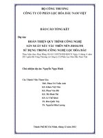
Fig. 6 Transfer function block diagraml of the ethylbenzeneproduction plant
The transfer function of the recycle, (23), was derived from the model configuration in Fig. 6.
GR =
GR =
G S − G1
G S .G 2
(22)
1,0911s 3 + 1,1522s 2 + 0,4002s + 0,0444
(23)
s 3 + 1,0648s 2 + 0,3776s + 0,0447
Fig. 7 shows the comparison of the transient responses of the nonlinear system and the linearized
model of system with recycle. The modeling mismatch problem leads to an oscillatory behaviour of
the linearized model.
0.07
nonlinear system
linear system
0.06
0.05
0.04
w
x
0.03
0.02
0.01
0
0
10
20
time (h)
30
40
50
Fig. 7 Comparison of the nonlinear and the linearized systems with recycle
061–7
33rd International Conference of SSCHE
May 22–26, 2006, Tatransk´e Matliare, Slovakia
Le-Tu-3, 061p.pdf
5. Conclusion
Modeling problem of a realistic industrial scaled coupled reactor/column process to produce
ethylbenzene is studied in this paper. The model was created using Matlab – Simulink environment.
Simulation experiments were carried out for various step-wise changes to demonstrate the dynamic
behaviour of the system. It is transparent that the recycle modifies the time constant as well as the static gain
of the overall system. Process identification was carried out in order to obtain the linearized model of the
ethylbenzene producing system.
In further study, the linear transfer function models, obtained above, will be utilized to eliminate the
recycle effect by introduction of a recycle compensator. To control the overall process with robust recycle
elimination, an adaptive controller with gain-scheduling performance can extend the compensator.
Acknowledgements:
The authors highly acknowledge the financial support of the Scientific Grant Agency of the Slovak Republic
under grants No. 1/1046/04 and 1/3081/06.
References
[1]
Ullmann’s Encyclopedia of Industrial Chemistry, Vol. A 10, 1987. VCH Verlagsgellschaft
mbH, D-6940 Weinheim, Germany.
[2]
Encyclopedia of Chemical Processing and Design 371.698/20, 1984. Marcel Dekker Inc.,
270 Madison Avenue, New York, 10016.
[3]
Alois Mészáros, Peter Mizsey, Marcell Horváth, Zsolt Fonyo, Dynamic analysis and control
of recycle processes 2004, SSCHE
[4]
Toxicology and Carcinogenesis Studies of Ethylbenzene (CAS No. 100-41-4) in F344/N
Rats and B6C3F1 Mice (Inhalation Studies),
/>
[5]
MORUD, J.; SKOGESTAD S.: Effects of recycle on dynamics and control of chemical processing
plants.1994, Computers Chem. Engng, 18, Suppl., S529-S534.
061–8