Magnetic anisotropy and coercivity in magnetic thin films
Bạn đang xem bản rút gọn của tài liệu. Xem và tải ngay bản đầy đủ của tài liệu tại đây (5.23 MB, 96 trang )
MAGNETIC ANISOTROPY AND COERCIVITY IN
MAGNETIC THIN FILMS
WANG SHUANG
(B. Sc., NJU)
A THESIS SUBMITTED
IN PARTIAL FULFILLMENT OF THE REQUIRMENTS
FOR THE DEGREE OF MASTER OF SCIENCE
DEPARTMENT OF MATERIALS SCIENCE
NATIONAL UNIVERSITY OF SINGAPORE
2000
ACKNOWLEDGEMENTS
ACKNOWLEDGEMENTS
This dissertation would not have been possible without the support of my
family, supervisor, colleagues and friends. I am deeply indebted to you all.
Firstly, I would like to show my respectful acknowledgement and my gratitude
to my supervisor, Dr. Ding Jun, which, great though it may be, will never attain to the
height of his assistance and his devotion. His guidance and encouragement has been
invaluable for my understanding of magnetism, magnetic materials, and thin films.
Secondly, I am much obliged to the technicians in our department: Ms. Li
Yueyue, Mr. Chan Yew Weng, Mr. Low Boon Yu and Ms. Agnes Lim, for their kind
help in my using of laboratory apparatus. My special thanks go to Ms. Agnes Lim, for
her kindness and patience in teaching me how to use AFM and SEM. Moreover, this
research could not be carried out smoothly without her help.
Thirdly, I would like to thank my colleagues and friends: Ng Wah Kian, Ng
Chee Wee, Lee Pooi See, Si Lun, Rao, Yu Shi, Chen Yunjie, Li Yangyang, and Fang
Aiping, for their friendship and encouragement during the whole course of my project.
Special thanks go to Ng Wah Kian and Lee Pooi See for our fruitful and successful
collaborations.
Finally, I feel deeply indebted to the academic staff in our department from
whom I got some understanding of science of materials: Prof. G. M. Chow, Prof. John
Wang, Dr. Gong Hao, Prof. Li Yi and Dr. Blackwood.
-i-
TABLE OF CONTENTES
TABLE OF CONTENTS
Acknowledgments………………………………………………………..…………i
Table of contents…………………………………………………………………...ii
Summary……………………………………………………………………….......vi
List of Tables& Figures…………………………………………………………..vii
Chapter 1: Introduction…………………………………………………………..1
1.1
Introduction
1
1.2
Magnetic anisotropy
2
1.3
Thesis overview
6
References
7
I Magnetic anisotropy in Al doped barium ferrite
Chapter 2: Magnetic anisotropy in Al doped barium ferrite nanoparticles……9
2.1 Introduction
9
2.2 Experimental set-up
11
2.3 Measurement results
13
2.3.1 Magnetic properties
13
2.3.2 Formation of the barium ferrite phase
17
2.3.3 Microstructural characteristics
24
2.4 Discussion
28
2.5 Conclusion
32
References
33
ii
TABLE OF CONTENTES
Chapter 3: In-plane Magnetic anisotropy in Al doped BaM thin films…………35
3.1 Introduction
35
3.2 Sample preparation
36
3.3 Measurement results
37
3.3.1 Magnetic properties
37
3.3.2 Microstructure
40
3.4 Discussion
42
3.5 Conclusion
44
References
45
II Magnetic Anisotropy in other Thin Films
Chapter 4: Magnetic anisotropy in sputtered nickel thin films…………………..49
4.1 Introduction
49
4.2 Experimental
50
4.3 Measurement results
51
4.3.1 Structure and surface morphology
51
4.3.2 Magnetic properties
56
4.4 Theoretical anisotropy field of nickel thin films
59
4.5Discussion
61
4.6 Summary
61
References
62
Chapter 5: Magnetic anisotropy in SiO2 doped cobalt ferrite thin films.……… 64
5.1 Introduction
64
iii
TABLE OF CONTENTES
5.2 Sample preparation
67
5.3 Measurement results
67
5.3.1 Structure and surface morphology
67
5.3.2 Magnetic measurement
70
5.4 Discussion
75
5.5 Conclusion
78
References
79
Chapter 6: Summary and suggestion for future work …………………………...81
6.1 Summary of present investigation
81
6.2 Possible future work
83
Appendix: Magnetic quantities conversion table in SI and CGS systems……
85
iv
SUMMARY
SUMMARY
Thin films with different possible mechanisms responsible for the magnetic
anisotropy have been fabricated; their preparation, microstructure and magnetic
properties, as well as the relations among them have been discussed in detail.
Magnetocrystalline anisotropy was investigated in Al doped barium ferrite
(Al-BaM) nanoparticles and thin films. Doping of Al leads to a higher coercivity in
BaAl2Fe10O19 nanoparticles. In the case of low concentrations of Al, BaAlFe11O19 thin
films show a longitudinal magnetic anisotropy. Mössbauer results show that Al
preferentially occupies the 12k sites in BaAl2Fe10O19 nanoparticles. Al was considered
to firstly enter the 2a sites in low concentrations. Our study shows that Al entering 12k
sites will give a positive contribution to the uniaxial anisotropy of barium ferrite,
whereas entering 2a sites gives a negative one. As a result, an increase of anisotropy
field and coercivity was found in BaAl2Fe10O19 nanoparticles, and a longitudinal
anisotropy was found in BaAlFe11O19 thin films.
Shape anisotropy was studied in sputtered nickel thin films. A columnar
structure, which might induce the shape anisotropy, was found by our TEM
observations. An investigation of surface topography in relation to magnetic
anisotropy was performed. It is indicated that nickel film formed in the initial stage
(45 nm) was a uniform and continuous layer on the native oxidized silicon substrate.
The film with a thickness of 78 nm exhibited high coercivity Hc (806 Oe) and high
squareness in the perpendicular direction to the film plane, while Hc of 349 Oe was
measured in the film plane. As the thickness increased, coercivity and magnetic
anisotropy reduced and a plane anisotropy was finally exhibited in thick films (∼500
nm).
v
SUMMARY
Both SiO2 doped and pure cobalt ferrite thin films were synthesized using a
sputtering method in order to study the stress-induced anisotropy. After adding a small
amount of SiO2 to cobalt ferrite, the deposited films on the naturally oxidized silicon
substrate exhibited a strong perpendicular anisotropy, while the pure cobalt ferrite
films showed magnetic isotropy. Our suggestion is that doping of SiO2 can inhibit the
grain growth. The study showed that stress is not at the origin of perpendicular
anisotropy in SiO2 doped cobalt ferrite thin films and thus we should look for its origin
elsewhere. As well, we found out that doping SiO2 increases the coercivity of cobalt
ferrite films. This may be interesting to future magneto-optical (MO) applications.
All along our study we considered that anisotropies: -magnetocrystalline
anisotropy, shape anisotropy, and stress-induced anisotropy play an important role in
magnetic materials, especially in thin films, and any of them may be predominant in
special circumstances.
vi
LIST OF TABLES AND FIGURES
LIST OF TABLES AND FIGURES
Table 1-1: Anisotropy constants in some substances………………………………………….2
Table 1-2: Demagnetizing factor of objects with different shapes……………………………4
Table 1-3: Magnetostriction constants of some substances (Units of 10-6)…………………...6
Table 2-1: Cation positions of barium ferrite hexagonal structure…………………………...10
Table 2-2: Comparison of coercivity and saturation magnetization for both pure and Al doped
barium ferrite prepared by different methods…………………………………………………14
Table 2-3: Lattice parameters a and c, and the unit cell volume V for the standard Ba-ferrite
structure and as a function of annealing temperature TA for ball milled Al-BaM samples…..25
Table 4-1: Samples studied in this work with thickness t, coercivity measured in the film
plane (Hc,//) and measured perpendicular to the film plane (Hc,⊥)…………………………….57
Table 4-2: Demagnetizing factor and anisotropy field for cylinders as a function of shape
factor k………………………………………………………………………………………..60
Table 5-1 Ion distribution and net moment per unit cell of Cobalt ferrite…………………...65
Table 5-2: Summary of coercivity values for CF and CS thin films annealing at different
temperatures ………………………………………………………………………………….72
Table 6.1: Summary of some uniaxial anisotropies………………………………………….83
Fig 1-1. Schematic drawing of a prolate ellipsoid with semi-major axis c and semi-minor axes
of equal length a………………………………………………………………………………..2
Fig. 1-2: Schematic mechanism of magnetostriction [4]………………………………...…….5
Fig. 2-1 Schematic crystal structure of hexagonal barium ferrite (BaFe12O19) ………………..9
Fig. 2-2 Hysteresis loops of BaFe12O19 (BaM) and ball-milled BaAl2Fe10O19 (Al-BaM) with
subsequent heat-treatment at 1100oC for 1 hour……………………………………………...14
Fig. 2-3 TA dependence of coercivity for BaFe12O19 and BaAl2Fe10O19 prepared by mechanical
milling and co-precipitation methods…………………………………………………………16
vii
LIST OF TABLES AND FIGURES
Fig. 2-4 TA dependence of saturation magnetization for BaFe12O19 and BaAl2Fe10O19 prepared
by mechanical milling and co-precipitation methods……………………………………..…..16
Fig.2-5 SEM pictures of the Al-BaM samples prepared by mechanical milling method
annealed at different temperatures(700, 900, 1000, 1100, 1200 and 1300 oC respectively)…18
Fig.2-6 SEM pictures of the Al-BaM samples prepared by chemical precipitation method
annealed at different temperatures(700, 900, 1000, 1100, 1200 and 1300 oC respectively)....19
Fig.2-7 SEM pictures of the BaM samples annealed at different temperatures(900, 1000,
1100, 1200 and 1300 oC respectively)……………………………………………………….20
Fig. 2-8 X-ray diffraction patterns of BaAl2Fe10O19 nanoparticles prepared by mechanical
milling with subsequent heat-treatment at different temperatures……………………………21
Fig 2.9 X-ray diffraction patterns of BaAl2Fe10O19 nanoparticles prepared by coprecipitation
with subsequent heat treatment at different temperatures……………………………………22
Fig. 2-10 DSC and TGA curves for the BaAl2Fe10O19 as-precipitated powder……………...23
Fig. 2-11 Mössbauer spectra of BaAl2Fe10O19 (a) as-milled and particles with subsequent
heat-treatment at (b) 700ºC, (c) 1100ºC and (d) 1300ºC for 1 hour………………………….28
Fig. 2-12 300k Mössbauer spectra for BaFe12-2xCoxMoxO19 samples at TA = 1200oC. ……....29
Fig. 3-1 TA dependence of coercivity (Hc) for Al doped barium ferrite on Si substrate……..38
Fig. 3-2 An in-plane hysteresis loop of Al doped barium ferrite on Si substrate with postannealing at 950°C for 5 min……………………………………………………………....…39
Fig. 3-3 SEM micrographs of Al doped barium ferrite thin films on Si substrate (a) in the asdeposited state and with post-annealing for 5 min. at (b) 800°C (c) 900°C (d) 1000°C and (e)
1200°C, respectively………………………………………………………………………….41
Fig. 3-4 Schematic drawing of the formation of grain geometry with two distinctive c-axis
orientations………………………………………………………………………….………..43
Fig. 4-1 X-ray diffraction patterns of films with different thickness (78 nm, 123 nm and ∼500
nm respectively)………………………………………………………………………………51
Fig. 4-2 An AFM graph of the film with a thickness of 45 nm…………………………..…..52
viii
LIST OF TABLES AND FIGURES
Fig. 4-3 AFM graphs of the film with a thickness of 78 nm with low (a) and high (b)
magnifications respectively…………………………………………………………………...53
Fig. 4-4 TEM micrographs of the surface (a) and cross section (b) for the film with a thickness
of 78 nm……………………………………………………………………………………….54
Fig. 4-5 AFM graph of the film with a thickness of 123 nm……………………………...….55
Fig. 4-6 AFM graphs of the film with a thickness of ∼500 nm with
low (a) and high (b)
magnifications respectively………………………………………………………………….56
Fig. 4-7
Hysteresis loops taken in the parallel and perpendicular to the film plane for the
film with a thickness of 78 nm and for the film with a thickness of ∼500 nm………………..58
Fig. 4-8 Demagnetizing factors of cylinder magnets…………………………………………59
Fig. 4-9 Variation of theoretical anisotropy field (Nickel) with shape factor k………..……….60
Fig. 5-1 Schematic drawing of the crystal structure of cobalt ferrite (CoFe2O4)……………..65
Fig. 5-2 X-ray diffraction patterns for both pure and SiO2 doped cobalt ferrite thin films after
a post-annealing at 1100ºC for half an hour…………………………………………………..68
Fig. 5-3 AFM graphs of (a) Cobalt ferrite (b) SiO2 doped cobalt ferrite in the as-deposited
state and ( c) Cobalt ferrite (d) SiO2 doped cobalt ferrite annealed at 1100oC for 30 min,
respectively……………………………………………………………………………………69
Fig.5-4 Hysteresis loops taken in the parallel and perpendicular to the film plane for
the cobalt ferrite film with a heat treatment of 1100ºC for half an hour……………..71
Fig. 5-5 Hysteresis loops taken in the parallel and perpendicular to the film plane for
the SiO2 doped cobalt ferrite film with a heat treatment of 1100ºC for half an
hour…………………………………………………………………………………...71
Fig. 5-6 TA dependence of coercivity taken in the parallel and perpendicular to the film plane
for pure and SiO2 doped cobalt ferrite thin films……………………………………………..73
Fig. 5-7 TA dependence of saturation magnetization for pure and SiO2 doped cobalt ferrite thin
films…………………………………………………………………………………………...73
Fig. 5-8 TA dependence of Mr/Ms ratio taken perpendicular to the film plane for pure and SiO2
doped cobalt ferrite thin films………………………………………………………………...74
ix
LIST OF TABLES AND FIGURES
Fig. 5-9 TA dependence of Mr/Ms ratio taken perpendicular to the film plane for pure and SiO2
doped cobalt ferrite thin films……………………………………………………………..….74
Fig. 5-10: Schematic drawing of magnetization of a material with negative magnetostriction
under compressive stress………………………………………………………………...……75
.
x
CHAPTER 1
INTRODUCTION
CHAPTER ONE
INTRODUCTION
1.1 Introduction
Magnetic materials play an increasingly important role in electrical,
mechanical and electronic systems, as well as in the generation and transformation of
electrical power, telecommunications, information storage and information processing
technologies.
Magnetic anisotropy has recently received great attention in technological
applications, i.e. magnetic sensors, high-end hard-disk read heads, and magnetic
memory chips, due to its fundamental and technological properties in high-density
magnetic recording. Recently, in high areal density recording, an areal density of 35
Gbit/in2 with the capability to write and read data with excellent error rates has been
produced by IBM. A new GMR read head which has a read/write speed that was
previously unattainable has also been introduced. In order to match the newly
introduced GMR-based read heads, media with ultra high coercivity, high anisotropy,
fine grains and tighter size distributions are desired [1]. As a result, a great deal of
effort should be put into the study of magnetic anisotropy and coercivity, as well as in
exploring the new media which are capable of supporting this high recording density.
Under these circumstances, understanding the mechanisms of different magnetic
anisotropies becomes more and more important.
The phenomenon of magnetic anisotropy is very complex, since the strength
of magnetic anisotropy of thin films can easily change with composition and
fabrication conditions. In addition, the polycrystalline nature of technologically
important thin films, which does not have specific orientations, makes it difficult to
1
CHAPTER 1
INTRODUCTION
control the magnetic anisotropy. Moreover, the requirement for optimized properties
substituting a variety of transition metals for various elements makes the magnetic
anisotropy even more complex. Therefore, it is necessary to investigate the magnetic
anisotropy in different materials, or in different fabrication methods on the same
material.
1.2 Magnetic anisotropy
Magnetic anisotropy can result from several reasons. It can be of
“crystallographic” nature, i.e. due to crystal structure or to directional ordering. As
well, anisotropy may arise from the particular shape or arrangement of particles and
the internal stress.
1) magnetocrystalline anisotropy: Magnetization depending on the orientation of the
crystal with respect to the external fields is called magnetocrystalline anisotropy [2].
One or more easy axes or planes may exist in the samples, along which magnetization
requires less work. The coupling between spin and orbital moments, and the
interaction between the charge distribution over the orbit and the electrostatic field of
the surrounding atoms, may give rise to magnetocrystalline anisotropy. In addition, in
non-cubic crystal lattices, the magnetostatic interaction among the atomic moments is
also anisotropic, which may give rise to easy directions or planes of magnetization [3].
Anisotropy constants found in several substances are summarized in Table 1-1.
Table 1-1: Anisotropy constants in some substances:
Structure
Cubic
Cubic
Hexagonal
Substance
Ni
CoO. Fe2O3
BaO. 6Fe2O3
K1 (105 ergs/cm3)
-0.5
20
33
K2 (105 ergs/cm3)
-0.2
2
CHAPTER 1
INTRODUCTION
The energy required to turn the magnetization away from the easy direction is
called the crystal anisotropy energy EK. In hexagonal structures it can be given as:
E K = K u1 sin 2 θ + K u 2 sin 4 θ (1.1)
where θ is the angle between the spontaneous magnetization and [0001] direction of a
hexagonal structure. Ku1 and Ku2 are magnetocrystalline anisotropy constants.
The anisotropy field is the field required to reverse the magnetization vector
from the easy axis to a hard direction of a uniaxial crystal. Assuming Ku2 is equal to
zero, the anisotropy field can be expressed as:
Hk = 2Ku1/Ms (1.2)
In cubic structures, this anisotropy energy can be written as:
(
)
E K = K 1 α 12α 22 + α 22α 32 + α 32α 12 + K 2α 12α 22α 32 (1.3)
where α1, α2, α3 are the direction cosines of the magnetization vector with respect to
the crystallographic axes, and K1, K2 are the crystal anisotropy constants.
:
M
a
c
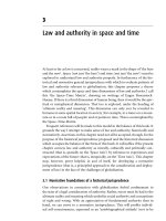
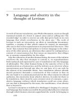
Fig 1-1. Schematic drawing of a prolate ellipsoid with semi-major axis c and semi-minor axes
of equal length a.
2) Shape anisotropy: Due to the existence of a demagnetizing field, a non-spherical
specimen will be easier to magnetize following a long axis instead of a short one [4].
When we consider a specimen in shape of a prolate ellipsoid (Fig.1-1) with semimajor axis c and semi-minor axes a and b of equal length, and the demagnetizing
3
CHAPTER 1
INTRODUCTION
factor is Na, Nb, Nc, respectively, the demagnetizing factors have the following
relationship:
N a + N b + N c = 1 (1.4)
Its shape anisotropy energy density can be given by:
E = 8π2(Na-Nc)Ms2 (1.5)
and the anisotropy field is:
H = −4π( N c − N a )M s (1.6)
Here the unit of H is Oe, while the unit of Ms is emu/cm3. Different demagnetizing
factors for this model are listed in Table 1-2.
Table 1-2: Demagnetizing factor of objects with different shapes:
Shape
Relationship
Sphere
a=b=c
Unlimited wide thin disc
Very long cylinders
Prolate Ellipsoid
Oblate Ellipsoid
c=b
c/a >>1
k =c/a>>1, a = b < c
a < b = c , k >>1
Demagnetizing factor N
1 (1.7)
N =N =N =+
a
b
c
3
N b = N c = 0 and N a = 1 (1.8)
Na = Nb =
Nc =
Nc =
1
and N c = 0 (1.9)
2
1
[ln(2k ) − 1] (1.10)
k2
π ⎡
2⎤
1 − ⎥ (1.11)
⎢
4 k ⎣ πk ⎦
3) Stress-induced anisotropy: It is known that applying a mechanical stress on
some materials [4] can lead to the creation of magnetic anisotropy. This stress-induced
anisotropy has the same origin as that of the magnetostriction (the dimension change
of a substance when it is exposed to a magnetic field), and is attributed to the
4
CHAPTER 1
INTRODUCTION
formation of a small fraction of ordered pairs under stress [5,6]. It can be described by
an energy term:
E me =
3
λ s σ sin 2 θ (1.12)
2
The stress anisotropy constant can be given by:
Κ=
3
λσ
2
(1.13)
Where λ is the magnetostriction constant, σ is the applied stress and θ is the angle
between the stress and the magnetization.
The plot in Fig. 1-2 schematically demonstrates the mechanism of
magnetostriction. The magnetostriction effect arises from an alignment of the
magnetic domains. The crystal's magnetic anisotropy couples the magnetic field with
the lattice distortion and, consequently, produces stress. Magnetostriction constants of
several substances are listed in Table 1-3.
Above Tc
∆L’
L’
L
∆L
Below Tc
H
Fig. 1-2: Schematic mechanism of magnetostriction [4].
5
CHAPTER 1
INTRODUCTION
Table 1-3: Magnetostriction constants of some substances (Units of 10-6)
Structure
Cubic
Cubic
Hexagonal
Substance
CoO. Fe2O3
Ni
BaO.6Fe2O3
λ100
λ111
-46
-24
λs
-110
-34
1.3 Thesis overview
The main goal of this thesis is to study the magnetic anisotropy in different
materials with different anisotropy mechanisms, so as to explore the feasibility of
preparing thin films with required magnetic properties for high-density magnetic
recording using sputtering techniques. Another goal of this work is the investigation
of magnetic and structural properties of different thin films.
The systems under study vary from nanoparticles to thin films, using a range
of reasonable materials for the study of magnetic anisotropy. The thesis has been
divided into two parts, each focusing on different mechanisms of magnetic anisotropy.
In part I, magnetocrystalline anisotropy was studied in Al-doped barium ferrite, both
in powders and in thin films. Other kinds of anisotorpies, i.e. shape anisotropy and
stress-induced anisotropy, were studied in part II.
Part I includes two chapters. Chapter 2 is the study of Al doped barium ferrite
powders. In Chapter 3, the effect of Al on magnetic anisotropy was studied on
sputtered thin films. Magnetocrystalline anisotropy was studied in different Al doping
ratios. The possible application of Al doped barium ferrite as a future high density,
longitudinal recording media was evaluated as well.
Besides magnetocrystalline anisotropy, other mechanisms of magnetic
anisotropy have also been investigated in Part II. Shape anisotropy is studied in
Chapter 4, in which the relationship between topographic and magnetic properties of
nickel thin films was discussed in detail. In Chapter 5, stress-induced anisotropy has
6
CHAPTER 1
INTRODUCTION
been studied in pure and SiO2 doped cobalt ferrite thin films. The properties of these
two films are compared to each other. The possibility of developing SiO2 doped cobalt
ferrite, a magnetic-optical recording media is also discussed in this chapter.
A summary of our experiments and a future tentative plan was given in
Chapter 6, based on the discussion of the preparation process, magnetic and
microstructure properties of thin films, as well as their possible magnetic anisotropy
mechanisms.
References:
1.
J. S. Li, Preparation and Characterization of Sputtered Barium Ferrite
Magnetic Thin Films, (UMI Dissertation Services, 1995), pp.5.
2.
H. J. F. Jansen, Science and technology of nanostructured magnetic materials,
ed. G. C. Hadjipanayis and G. A. Prinz, (Plenum, New York, 1991) p.349
3.
H. Zijlstra, Ferromagnetic materials, vol. 3, ed. E. P. Wohlfarth (Elsevier,
Amsterdam, 1982) p.54.
4.
B. D. Cullity, Introduction to Magnetic Materials, (Addison-Wesley
Publishing Company, Canada, 1972), P.273.
5.
A. Hernando, H. Szymczak and H. K. Lachowicz, Physics of magnetic
materials, ed. W. Gorzkowski, H. K. Lachowicz and H. Szymczak, (World
Scientific, Singapore, 1987) p.451.
6.
J. Haimovich, T. Jagielinski and T. Egami, J. Appl. Phys, 57(1), p.3581
(1985).
7
Part I
Magnetic Anisotropy in Al doped barium ferrite
CHAPTER 2
MAGNETIC ANISOTROPY IN Al-BaM NANOPARTICLES
CHAPTER TWO
Magnetic anisotropy in Al doped barium ferrite nanoparticles
2.1 Introduction
The present interest in improving the basic magnetic properties of M-type
hexagonal BaFe12O19 by ion substitution is closely connected with the advantageous
applications of longitudinal magnetic recording [1-4]. Many efforts have been put in
searching for new elements as more effective additives. Among these additives, Al is
the most promising one because it can improve film squareness [5,6], enhance a good
c-axis in-plain thin film texture [7], and achieve a high coercivity, up to 9.5 kOe, the
highest reported value so far [1-3]. In this sense, the investigation of the exact role of
Al in barium ferrite becomes very important.
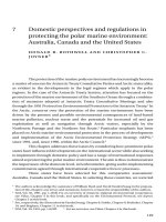
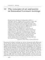
Octahedral
site
Tetrahedral site
Bipyramidal site
Fig. 2-1 Schematic crystal structure of hexagonal barium ferrite (BaFe12O19) [28].
9
CHAPTER 2
MAGNETIC ANISOTROPY IN Al-BaM NANOPARTICLES
Barium Ferrite (BaFe12O19) has a hexagonal structure. Its lattice parameters are
a=23.20Å and c=5.88Å with a unit cell volume of 694.7 Å3. The O2- ions layer
sequence perpendicular to the [001] direction is ABAB… or ACAC… as shown in
Fig. 2-1. Every five oxygen layers, one O2- ion is replaced with Ba2+. Five oxygen
layers make one molecule and two molecules make one unit cell, resulting a total of
64 atoms. Each molecule shows 180o rotational symmetry around the hexagonal c-axis
against the lower or upper molecule.
Fe3+ occurs in barium ferrite in five distinct crystallographic sites, designed as
the octahedral sites 12k, 2a and 4f2, the tetrahedral site 4f1, and the bipyramidal site
2b, in the ratio 6:1:2:2:1, respectively. In the magnetically ordered state, the spins of
the 12k, 2a and 2b sublattices are aligned parallel to the crystallographic c axis
whereas the 4f1 and 4f2 spins are oriented antiparallel to the former [12]. The ionic
moments of variable strength and direction of Fe3+ are summarized in Table 2-1. In
fact, Fe3+ ions might be occupied by a variety of metal ions. Different additives prefer
occupying different crystallographic sites in barium ferrite [8-11].
Table 2-1: Cation positions of barium ferrite hexagonal structure.
Coordination number
6 (Octahedral site)
5 (Bipyramidal site)
4 (Tetrahedral site)
6 (Octahedral site)
6 (Octahedral site)
Wyckoff’s notation
2a
2b
4f1
4f2
12k
Fraction % Fe3+ spin orientation
8.33
8.33
16.67
16.67
50.00
Al substitution is known to have a profound influence on the magnetic
properties of barium ferrite. For instance, Al can increase its HA and decrease its Ms
[12, 32]. The reason is that the total magnetization per formula unit in barium ferrite
can be described as:
10
CHAPTER 2
MAGNETIC ANISOTROPY IN Al-BaM NANOPARTICLES
M s (T ) = 6σ k (T) − 2σ f 1 (T ) − 2σ f 2 (T ) + σ b (T ) + σ a (T) (2.1)
where the variable σ denote the magnetization of one Fe3+ ion in each sublattice site.
The occupation by Al for Fe3 of those crystallographic sites with negative
contributions may decrease Ms and simultaneously increase HA (due to HA = 2K/Ms).
Rensen based on his previous work and Mössbauer measurements, [11] believed that
Al3+ first occupy 2a sites then 12k sites. In contrast, Suchet [13] presented a strong
preference of Al to the 4f1 and 2a sites. The possibility of increasing the anisotropy
field HA of barium ferrite would make this compound very useful as a future magnetic
recording medium.
In the present chapter, the substitution effect of Al on the magnetic anisotropy
in hexagonal barium ferrite was investigated. Samples were produced by both
mechanical milling and co-precipitation methods in which Fe3+ being replaced by
Al3+. Crystallographic features and magnetic properties of Al doped barium ferrite
were studied and compared to those of pure barium ferrite. The ionic moment, local
environment, and the population of each distinct crystallographic site were obtained
from Mössbauer spectroscopy.
2.2 Experimental set-up
Two methods, i.e. mechanical milling and chemical co-precipitation were used
to produce Al doped barium ferrite in this study.
Mechanical milling has been proved to be a powerful and convenient method
for obtaining fine and nanocrystalline materials, and recently it was also introduced in
preparation of barium ferrite [14-17]. The starting materials used in this study are
BaCO3, Fe2O3, and Al2O3. A mixture of 1BaCO3 + 5 Fe2O3 + Al2O3 plus an excess of
10% of BaCO3, which was considered as the formation of single Ba-ferrite phase [14-
11
CHAPTER 2
MAGNETIC ANISOTROPY IN Al-BaM NANOPARTICLES
17], was loaded in a hardened steel vial together with fifteen 10mm steel balls. The
mixture with a weight of 20g was milled in a planetary ball mill (Fritsch Pulverisette
5) in closed containers of hardened steel for 36 h in atmosphere. A ball-to-powder
mass charge ratio of 10:1 was chosen. In comparison, BaCO3 + 6Fe2O3 plus 10% of
excess of BaCO3 (i.e. without Al substitution) were also mechanically milled under
the same conditions as described above.
Co-precipitation, a pure chemical method, was also used to fabricate fine
nanocrystalline Al-BaM particles with a high purity and a narrow size distribution. A
solution of barium nitrate (Ba(NO3)2), iron(III) chloride-6-hydrate (FeCl3. 6H2O),
(both with a minimum purity of 99%), and Aluminum chloride (AlCl3) was prepared
in the ratio of 1Ba(NO3)2+ 7FeCl3 + 1.4 AlCl3. The excess of Ba(NO3)2 was used to
compensating Ba2+ for its loss during the coprecipitation process. Ammonia solution
(NH4OH), 28 wt% of NH3, was added into the solution. A magnetic stirrer was used
for complete dissolving. The ammonia solution was added until a pH value of 10 was
obtained. The suspension was then filtered, washed and freeze-dried using a freeze
dryer.
The resultant powder prepared by using the above two methods was put into a
die then pressed into cylindrical specimens with a diameter of 5mm and a weight of
about 0.1 g each. Thermal treatment to the samples was performed for 1 hour within
the temperature range of 700 to 1300°C in air. X-ray diffraction measurements were
performed using a PW 1710 diffractometer with Cu-Kα radiation. A current of 40 mA,
a voltage of 45 kV and a Cu Kα radiation with a wavelength of 1.5402 Å were the
working conditions of the generator and the diffractometer.
Mössbauer measurements were performed by a
57
Fe-Mössbauer spectroscopy
(Austin S-600). The Mössbauer source used in this study consists of 57Co embedded
12
CHAPTER 2
MAGNETIC ANISOTROPY IN Al-BaM NANOPARTICLES
in a copper lattice. The velocities of the source were chosen to vary from –12 to +12
mm/s. The data were collected for two days to obtain sufficient counts of the peaks of
the spectrum.
The microstructure of the sample was studied by a Field Emission Scanning
Electron Microscope (SEM Philips XL 30 FEG) and an Energy Dispersive X-ray
Spectrometry (EDX) determined the composition of the resultant powder. Thermal
analysis was carried out by a Differential Scanning Calorimetry (DSC) and a
Thermogravimetric Analysis (TGA) at a heating rate of 10°C/min. Magnetic
properties of the pressed isotropic cylinder specimens were measured by a Vibrating
Sample Magnetometer (VSM Oxford Instruments) with a maximum applied field of
90 kOe at room temperature.
2.3 Measurement results
2.3.1 Magnetic properties
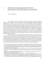
Fig 2.2 shows the room-temperature hysteresis loops of Al-BaM and BaM
compacted powders prepared by mechanical milling method at TA of 1100ºC, for
fields applied parallel to the plane of the sample. Since powder samples are isotropic,
usually the hysteresis loops measured with the field applied in two directions (in
parallel and perpendicular to the plane of the films) are identical. The BaM sample
shows a coercivity of 4.5 kOe and a saturation of 62.1 emu/g, while a coercivity of 9.3
kOe and a saturation of 36.6 emu/g were possessed by the Al-BaM sample. The
results seem to reflect that adding Al to BaM may increase its coercivity and in the
meanwhile decrease its Ms. Magnetic properties of BaM and Al-BaM samples are
summarized in Table 2-2.
13
CHAPTER 2
MAGNETIC ANISOTROPY IN Al-BaM NANOPARTICLES
Fig 2.3 shows the coercivity as a function of the annealing temperature. A
high coercivity up to 9.3 kOe was achieved after substituting Al for Fe in barium
ferrite by mechanical milling method. Using co-precipitation method, a coercivity as
80
60
Magnetization (emu/g)
40
20
0
-20
-40
BaAl2Fe 10O 19
BaFe 12O 19
-60
-80
-40
-20
0
20
40
Magnetic Field (kOe)
Fig. 2-2 Hysteresis loops of BaFe12O19 (BaM) and ball-milled BaAl2Fe10O19 (Al-BaM) with
subsequent heat-treatment at 1100oC for 1 hour.
Table 2-2: Comparison of coercivity and saturation magnetization for both pure and Al doped
barium ferrite prepared by different methods.
TA (OC)
methods
BaM
ball milling
HC (kOe)
Al-BaM
ball milling
700
800
900
1000
1100
1200
1300
5.25
5.65
5.53
5.29
4.45
3.36
------
0.19
0.30
6.32
8.77
9.23
8.16
5.08
Al-BaM
Coprecipitation
0.113
1.69
3.58
3.68
6.80
8.40
7.09
BaM
ball milling
MS (emu/g)
Al-BaM
ball milling
23.75
56.68
59.29
61.33
62.12
63.07
------
1.40
1.50
21.80
44.10
36.60
34.10
33.03
Al-BaM
Coprecipitation
4.44
15.8
33.33
32.10
26.71
30.14
35.27
14