Digital control in power electronics by simone busoand paolo mattavelli
Bạn đang xem bản rút gọn của tài liệu. Xem và tải ngay bản đầy đủ của tài liệu tại đây (1.54 MB, 159 trang )
Digital Control in Power
Electronics
Copyright © 2006 by Morgan & Claypool
All rights reserved. No part of this publication may be reproduced, stored in a retrieval system, or transmitted in
any form or by any means—electronic, mechanical, photocopy, recording, or any other except for brief quotations
in printed reviews, without the prior permission of the publisher.
Digital Control in Power Electronics
Simone Buso and Paolo Mattavelli
www.morganclaypool.com
ISBN-10: 1598291122
ISBN-13: 9781598291124
paperback
paperback
ISBN-10: 1598291130
ISBN-13: 9781598291131
ebook
ebook
DOI10.2200/S00047ED1V01Y200609PEL002
A lecture in the Morgan & Claypool Synthesis Series
LECTURES ON POWER ELECTRONICS #2
Lecture #2
Series Editor: Jerry Hudgins, University of Nebraska-Lincoln
Series ISSN: 1930-9525
Series ISSN: 1930-9533
electronic
First Edition
10 9 8 7 6 5 4 3 2 1
Printed in the United States of America
Digital Control in Power
Electronics
Simone Buso
Department of Information Engineering
University of Padova, Italy
Paolo Mattavelli
Department of Electrical, Mechanical and
Management Engineering
University of Udine, Italy
LECTURES ON POWER ELECTRONICS #2
M
&C
Mor gan
& Cl aypool
Publishers
iv
ABSTRACT
This book presents the reader, whether an electrical engineering student in power electronics
or a design engineer, some typical power converter control problems and their basic digital
solutions, based on the most widespread digital control techniques. The presentation is focused
on different applications of the same power converter topology, the half-bridge voltage source
inverter, considered both in its single- and three-phase implementation. This is chosen as
the case study because, besides being simple and well known, it allows the discussion of a
significant spectrum of the more frequently encountered digital control applications in power
electronics, from digital pulse width modulation (DPWM) and space vector modulation (SVM),
to inverter output current and voltage control. The book aims to serve two purposes: to give
a basic, introductory knowledge of the digital control techniques applied to power converters,
and to raise the interest for discrete time control theory, stimulating new developments in its
application to switching power converters.
KEYWORDS
Digital control in power electronics, Discrete time control theory, Half-bridge voltage source
converters, Power converters, Power electronics
v
Contents
1.
Introduction: Digital Control Application to Power Electronic Circuits . . . . . . . . . . . .
1.1 Modern Power Electronics . . . . . . . . . . . . . . . . . . . . . . . . . . . . . . . . . . . . . . . . . . . . . . . . .
1.2 Why Digital Control . . . . . . . . . . . . . . . . . . . . . . . . . . . . . . . . . . . . . . . . . . . . . . . . . . . . . .
1.3 Trends and Perspectives . . . . . . . . . . . . . . . . . . . . . . . . . . . . . . . . . . . . . . . . . . . . . . . . . . . .
1.4 What is in this Book . . . . . . . . . . . . . . . . . . . . . . . . . . . . . . . . . . . . . . . . . . . . . . . . . . . . . . .
2.
The Test Case: a Single-Phase Voltage Source Inverter . . . . . . . . . . . . . . . . . . . . . . . . . . . .
2.1 The Voltage Source Inverter . . . . . . . . . . . . . . . . . . . . . . . . . . . . . . . . . . . . . . . . . . . . . . . .
2.1.1 Fundamental Components . . . . . . . . . . . . . . . . . . . . . . . . . . . . . . . . . . . . . . . . . .
2.1.2 Required Additional Electronics: Driving and Sensing . . . . . . . . . . . . . . . . .
2.1.3 Principle of Operation . . . . . . . . . . . . . . . . . . . . . . . . . . . . . . . . . . . . . . . . . . . . . .
2.1.4 Dead-Times . . . . . . . . . . . . . . . . . . . . . . . . . . . . . . . . . . . . . . . . . . . . . . . . . . . . . . .
2.2 Low-Level Control of the Voltage Source Inverter: PWM Modulation . . . . . . . . .
2.2.1 Analog PWM: the Naturally Sampled Implementation . . . . . . . . . . . . . . . .
2.2.2 Digital PWM: the Uniformly Sampled Implementation . . . . . . . . . . . . . . .
2.2.3 Single Update and Double Update PWM Mode . . . . . . . . . . . . . . . . . . . . . .
2.2.4 Minimization of Modulator Delay: a Motivation
for Multisampling . . . . . . . . . . . . . . . . . . . . . . . . . . . . . . . . . . . . . . . . . . . . . . . . . .
2.3 Analog Control Approaches . . . . . . . . . . . . . . . . . . . . . . . . . . . . . . . . . . . . . . . . . . . . . . . .
2.3.1 Linear Current Control: PI Solution . . . . . . . . . . . . . . . . . . . . . . . . . . . . . . . . .
2.3.2 Nonlinear Current Control: Hysteresis Control . . . . . . . . . . . . . . . . . . . . . . .
3.
Digital Current Mode Control . . . . . . . . . . . . . . . . . . . . . . . . . . . . . . . . . . . . . . . . . . . . . . . . . .
3.1 Requirements of the Digital Controller . . . . . . . . . . . . . . . . . . . . . . . . . . . . . . . . . . . . . .
3.1.1 Signal Conditioning and Sampling . . . . . . . . . . . . . . . . . . . . . . . . . . . . . . . . . .
3.1.2 Synchronization Between Sampling and PWM . . . . . . . . . . . . . . . . . . . . . . .
3.1.3 Quantization Noise and Arithmetic Noise . . . . . . . . . . . . . . . . . . . . . . . . . . . .
3.2 Basic Digital Current Control Implementations . . . . . . . . . . . . . . . . . . . . . . . . . . . . . .
3.2.1 The Proportional Integral Controller: Overview . . . . . . . . . . . . . . . . . . . . . . .
3.2.2 Simplified Dynamic Model of Delays . . . . . . . . . . . . . . . . . . . . . . . . . . . . . . . .
3.2.3 The Proportional Integral Controller: Discretization Strategies . . . . . . . . .
3.2.4 Effects of the Computation Delay . . . . . . . . . . . . . . . . . . . . . . . . . . . . . . . . . . .
vi
CONTENTS
3.2.5
3.2.6
3.2.7
Derivation of a Discrete Time Domain Converter Dynamic Model . . . . .
Minimization of the Computation Delay . . . . . . . . . . . . . . . . . . . . . . . . . . . . .
The Predictive Controller . . . . . . . . . . . . . . . . . . . . . . . . . . . . . . . . . . . . . . . . . . .
4.
Extension to Three-Phase Inverters . . . . . . . . . . . . . . . . . . . . . . . . . . . . . . . . . . . . . . . . . . . . .
4.1 The αβ Transformation . . . . . . . . . . . . . . . . . . . . . . . . . . . . . . . . . . . . . . . . . . . . . . . . . . . .
4.2 Space Vector Modulation . . . . . . . . . . . . . . . . . . . . . . . . . . . . . . . . . . . . . . . . . . . . . . . . . .
4.2.1 Space Vector Modulation Based Controllers . . . . . . . . . . . . . . . . . . . . . . . . . .
4.3 The Rotating Reference Frame Current Controller . . . . . . . . . . . . . . . . . . . . . . . . . . .
4.3.1 Park’s Transformation . . . . . . . . . . . . . . . . . . . . . . . . . . . . . . . . . . . . . . . . . . . . . .
4.3.2 Design of a Rotating Reference Frame PI Current Controller . . . . . . . . . .
4.3.3 A Different Implementation of the Rotating Reference Frame
PI Current Controller . . . . . . . . . . . . . . . . . . . . . . . . . . . . . . . . . . . . . . . . . . . . . .
5.
External Control Loops . . . . . . . . . . . . . . . . . . . . . . . . . . . . . . . . . . . . . . . . . . . . . . . . . . . . . . . . .
5.1 Modeling the Internal Current Loop . . . . . . . . . . . . . . . . . . . . . . . . . . . . . . . . . . . . . . . .
5.2 Design of Voltage Controllers . . . . . . . . . . . . . . . . . . . . . . . . . . . . . . . . . . . . . . . . . . . . . .
5.2.1 Possible Strategies: Large and Narrow Bandwidth Controllers . . . . . . . . . .
5.3 Large Bandwidth Controllers . . . . . . . . . . . . . . . . . . . . . . . . . . . . . . . . . . . . . . . . . . . . . . .
5.3.1 PI Controller . . . . . . . . . . . . . . . . . . . . . . . . . . . . . . . . . . . . . . . . . . . . . . . . . . . . . .
5.3.2 The Predictive Controller . . . . . . . . . . . . . . . . . . . . . . . . . . . . . . . . . . . . . . . . . . .
5.4 Narrow Bandwidth Controllers . . . . . . . . . . . . . . . . . . . . . . . . . . . . . . . . . . . . . . . . . . . . .
5.4.1 The Repetitive-Based Voltage Controller . . . . . . . . . . . . . . . . . . . . . . . . . . . . .
5.4.2 The DFT Filter Based Voltage Controller . . . . . . . . . . . . . . . . . . . . . . . . . . . .
5.5 Other Applications of the Current Controlled VSI . . . . . . . . . . . . . . . . . . . . . . . . . . . .
5.5.1 The Controlled Rectifier . . . . . . . . . . . . . . . . . . . . . . . . . . . . . . . . . . . . . . . . . . . .
5.5.2 The Active Power Filter . . . . . . . . . . . . . . . . . . . . . . . . . . . . . . . . . . . . . . . . . . . .
6.
Conclusions . . . . . . . . . . . . . . . . . . . . . . . . . . . . . . . . . . . . . . . . . . . . . . . . . . . . . . . . . . . . . . . . . . . .
7.
About the Authors . . . . . . . . . . . . . . . . . . . . . . . . . . . . . . . . . . . . . . . . . . . . . . . . . . . . . . . . . . . . . .
1
CHAPTER 1
Introduction: Digital Control
Application to Power Electronic
Circuits
Power electronics and discrete time system theory have been closely related to each other from
the very beginning. This statement may seem surprising at first, but, if one thinks of switch
mode power supplies as variable structure periodic systems, whose state is determined by logic
signals, the connection becomes immediately clearer. A proof of this may also be found in
the first, fundamental technical papers dealing with the analysis and modeling of pulse width
modulated power supplies or peak current mode controlled dc–dc converters: they often provide
a mathematical representation of both the switching converters and the related control circuits,
resembling or identical to that of sampled data dynamic systems.
This fundamental contiguousness of the two apparently far areas of engineering is probably
the strongest, more basic motivation for the considerable amount of research that, over the
years, has been dedicated to the application of digital control to power electronic circuits. From
the original, basic idea of implementing current or voltage controllers for switching converters
using digital signal processors or microcontrollers, which represents the foundation of all current
industrial applications, the research focus has moved to more sophisticated approaches, where
the design of custom integrated digital controllers is no longer presented like an academic
curiosity, but is rather perceived like a sound, viable solution for the next generation of highperformance power supplies.
If we consider the acceleration in the scientific production related to these topics in the
more recent years, we can easily anticipate, for a not too far ahead future, the creation of
energy processing circuits, where power devices and control logic can be built on the same
semiconductor die. From this standpoint, the distance we see today between the tools and the
design methodology of power electronics engineers and those of analog and/or digital integrated
circuit designers can be expected to significantly reduce in the next few years.
2
DIGITAL CONTROL IN POWER ELECTRONICS
We have to admit that, in this complex scenario, the purpose of this book is very simple. We just would like to introduce the reader to basic control problems in power electronic
circuits and to illustrate the more classical, widely applied digital solutions to those problems.
We hope this will serve two purposes: first, to give a basic, introductory knowledge of the
digital control techniques applied to power converters, and second, to raise the interest for discrete time control theory, hopefully stimulating new developments in its application to power
converters.
1.1
MODERN POWER ELECTRONICS
Classical power electronics may be considered, under several points of view, a mature discipline.
The technology and engineering of discrete component based switch mode power supplies
are nowadays fully developed industry application areas, where one does not expect to see
any outstanding innovation, at least in the near future. Symmetrically, at the present time,
the research fields concerning power converter topologies and the related conventional, analog
control strategies seem to have been thoroughly explored.
On the other hand, we can identify some very promising research fields where the future
of power electronics is likely to be found. For example, a considerable opportunity for innovation
can be expected in the field of large bandgap semiconductor devices, in particular if we consider
the semiconductor technologies based on silicon carbide, SiC, gallium arsenide, GaAs, and
gallium nitride, GaN. These could, in the near future, prove to be practically usable not only for
ultra-high-frequency amplification of radio signals, but also for power conversion, opening the
door to high-frequency (multi-MHz) and/or high-temperature power converter circuits and,
consequently, to a very significant leap in the achievable power densities.
The rush for higher and higher power densities motivates research also in other directions.
Among these, we would like to mention three that, in our vision, are going to play a very
significant role. The first is the integration in a single device of magnetic and capacitive passive
components, which may allow the implementation of minimum volume, quasi monolithic,
converters. The second is related to the analysis and mitigation of electromagnetic interference
(EMI), which is likely to become fundamental for the design of compact, high frequency,
converters, where critical autosusceptibility problems can be expected. The third one is the
development of technologies and design tools allowing the integration of control circuits and
power devices on the same semiconductor chip, according to the so-called smart power concept.
These research areas represent good examples of what, in our vision, can be considered modern
power electronics.
From this standpoint, the application of digital control techniques to switch mode power
supplies can play a very significant role. Indeed, the integration of complex control functions, such as those that are likely to be required by the next generation power supplies,
INTRODUCTION: DIGITAL CONTROL APPLICATION
is a problem that can realistically be tackled only with the powerful tools of digital control
design.
1.2
WHY DIGITAL CONTROL
The application of digital control techniques to switch mode power supplies has always been
considered very interesting, mainly because of the several advantages a digital controller shows,
when compared to an analog one.
Surely, the most relevant one is the possibility it offers for implementing sophisticated
control laws, taking care of nonlinearities, parameter variations or construction tolerances by
means of self-analysis and autotuning strategies, very difficult or impossible to implement
analogically.
Another very important advantage is the flexibility inherent in any digital controller, which
allows the designer to modify the control strategy, or even to totally reprogram it, without the
need for significant hardware modifications. Also very important are the higher tolerance to
signal noise and the complete absence of ageing effects or thermal drifts.
In addition, we must consider that, nowadays, a large variety of electronic devices, from
home appliances to industrial instrumentation, require the presence of some form of man to
machine interface (MMI). Its implementation is almost impossible without having some kind
of embedded microprocessor. The utilization of the computational power, which thus becomes
available, also for lower level control tasks is almost unavoidable.
For these reasons, the application of digital controllers has been increasingly spreading
and has become the only effective solution for a whole lot of industrial power supply production
areas. To give an example, adjustable speed drives (ASDs) and uninterruptible power supplies
(UPSs) are nowadays fully controlled by digital means.
The increasing availability of low-cost, high-performance, microcontrollers and digital
signal processors stimulates the diffusion of digital controllers also in areas where the cost of
the control circuitry is a truly critical issue, like that of power supplies for portable equipment,
battery chargers, electronic welders and several others.
However, a significant increase of digital control applications in these very competing
markets is not likely to take place until new implementation methods, different from the traditional microcontroller or DSP unit application, prove their viability. From this standpoint, the
research efforts towards digital control applications need to be focused on the design of custom
integrated circuits, more than on algorithm design and implementation. Issues such as occupied
area minimization, scalability, power consumption minimization and limit cycle containment
play a key role. The power electronics engineer is, in this case, deeply involved in the solution
of digital integrated circuit design problems, a role that will be more and more common in the
future.
3
4
DIGITAL CONTROL IN POWER ELECTRONICS
1.3
TRENDS AND PERSPECTIVES
From the above discussion, it will be no surprise if we say that we consider the increasing
diffusion of digital control in power electronics virtually unstoppable. The advantages of the
digital control circuits, as we have briefly outlined in the previous section, are so evident that, in
the end, all the currently available analog integrated control solutions are going to be replaced
by new ones, embedding some form of digital signal processing core. Indeed, it is immediate to
recognize that the digital control features perfectly match the needs of present and, even more,
future, highly integrated, power converters. The point is only how long this process is going
to take. We can try to outline the future development of digital controllers distinguishing the
different application areas.
The medium-to high-power applications, such as electrical drives, test power supplies,
uninterruptible power supplies, renewable energy source interfaces, are likely to be developed
according to the same basic hardware organization for a long time to come. The application of
microcontroller units or digital signal processors in this area is likely to remain very intensive.
The evolution trend will probably be represented by the increasing integration of higher level
functions, e.g., those concerning communication protocols for local area networks or field buses,
man to machine interfaces, remote diagnostic capabilities, that currently require the adoption
of different signal processing units, with low-level control functions.
As far as the low power applications are concerned, as we mentioned in the previous
section, we cannot, at the moment, describe an established market for digital controllers. However, the application of digital control in this field is the object of an intensive research. In the
near future, new control solutions can be anticipated, which will replace analog controllers with
equivalent digital solutions, in a way that can be considered almost transparent to the user.
Successively, the complete integration of power and control circuitry is likely to determine a
radical change in the way low power converters are designed.
1.4
WHAT IS IN THIS BOOK
As mentioned above, in front of the complex and exciting perspectives for the application
of digital control to power converters, we decided to aim this book at giving the reader a
basic and introductory knowledge of some typical power converter control problems and their
digital solutions. Referring to the above discussion, we decided to dedicate the largest part
of our presentation to topics that can be considered the current state of the art for industrial
applications of digitally controlled power supplies.
The book is consequently proposed to power electronics students, or designers, who would
like to have an overview of the most widespread digital control techniques. It is not intended to
provide an exhaustive description of all the possible solutions for any considered problem, nor
INTRODUCTION: DIGITAL CONTROL APPLICATION
to describe the more recent research advances related to any of them. This choice has allowed
us to keep the presentation of the selected materials relatively agile and to give it an immediate,
practical usefulness.
Accordingly, what the reader should know to take full advantage of the contents that are
presented here is relatively little: a basic knowledge of some power electronic circuits (essentially
half-bridge and full-bridge voltage source inverters) and the fundamental mathematical tools
that are commonly employed in modeling continuous and discrete time dynamic system (Laplace
transform and Z transform, for starters) will perfectly do.
As the reader will realize, if he or she will have the patience to follow us, the book is
conceived to explain the different concepts essentially by means of examples. To limit the risk
of being confusing, proposing several different topologies, we decided to take into account a
single, relatively simple test case and develop its analysis all along the text. Doing so, the contents
we have included allowed us to present, organically and without too many context changes, a
significant amount of control techniques and related implementation details.
In summary, the book is organized as follows. Chapter 2 describes the considered test
case, a voltage source inverter, and the first control problem, i.e., the implementation of a
current control loop, discussing in the first place its analog, i.e., continuous time, solutions.
Chapter 3 is dedicated to digital control solutions for the same problem: in the beginning
we present a relatively simple one, i.e., the discretization of continuous time controllers. In
the following, other fully digital solutions, like those based on discrete time state feedback
and pole placement, are presented. Chapter 4 is dedicated to the extension to three phase
systems of the solutions presented for the single-phase inverter. In this chapter we discuss space
vector modulation (SVM) and rotating reference frame current controllers, like those based
on Park’s transformation. Finally, Chapter 5 presents the implementation of external control
loops, wrapped around the current controller, which is typically known as a multiloop controller
organization. The design of an output voltage controller, as is needed in uninterruptible power
supplies, is considered first. Both large bandwidth control strategies and narrow bandwidth
ones, based on the repetitive control concept, are analyzed. After that, and in conclusion, two
other significant examples of multiloop converter control, which we may find in controlled
rectifiers and active power filters, are considered and briefly discussed.
5
7
CHAPTER 2
The Test Case: a Single-Phase
Voltage Source Inverter
The aim of this chapter is to introduce the test case we will be dealing with in the following
sections. As mentioned in the introduction, it would be extremely difficult to describe the
numerous applications of digital control to switch mode power supplies, since this is currently
employed in very wide variety of cases. In order not to confuse the reader with a puzzle of
several different circuit topologies and related controllers, what we intend to do is to consider
just a single, simple application example, where the basics of the more commonly employed
digital control strategies can be effectively explained. Of course, the concepts we are going to
illustrate, referring to our test case, can find a successful application also to other converter
topologies.
The content of this chapter is made up, in the first place, by an introductory, but fairly
complete, description of the power converter we will be discussing throughout this book, i.e.,
the half-bridge voltage source inverter. Secondly, the principles of its more commonly adopted
low-level control strategy, namely pulse width modulation (PWM), will be explained, at first in
the continuous time domain, and then in the discrete time domain. The issues related to PWM
control modeling are fundamental for the correct formulation of a switch mode power supply
(SMPS) digital, or even analog, control problem, so this part of the chapter can be considered
essential to the understanding of everything that follows. The final part of the chapter is instead
dedicated to a summary of the more conventional analog control strategies, which will serve as
a reference for all the following developments.
2.1
THE VOLTAGE SOURCE INVERTER
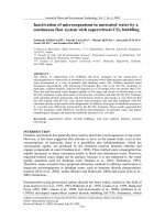
The considered test case is shown in Fig. 2.1. As can be seen, the power converter we want to take
into consideration is a single-phase voltage source inverter (VSI). The VSI has a conventional
topological structure, which is known as a half bridge. We will now analyze the power converter’s
organization in some detail.
8
DIGITAL CONTROL IN POWER ELECTRONICS
S1
+
-
G1
VDC
ES
LS
D1
RS
E1
C
O
+
+
-
VDC
IO
G2
D2
S2
E2
FIGURE 2.1: Half-bridge voltage source inverter.
2.1.1
Fundamental Components
The ideal voltage sources VDC at the input are, in practice, approximately implemented by means
of suitably sized capacitors, fed by a primary energy source. They are normally large enough
to store a considerable amount of energy and their purpose is to deliver it to the load, rapidly
enough not to cause the circulation of substantial high-frequency currents through the primary
source. This, in turn, can be represented by any real dc voltage source, from batteries to line-fed
rectifiers, depending on the particular application. However, for our discussion, modeling the
energy source as an ideal voltage source does not represent any limitation.
The power switches are represented by the conventional IGBT symbol, but it is possible to find implementations with very different switch technologies, such as, for instance,
power MOSFETs or, for very high power application, thyristors. As can be seen, each switch
is paralleled to a free-wheeling diode, whose purpose is to make the switch bidirectional,
at least as far as the current flow is concerned. This interesting property makes the VSI
of Fig. 2.1 a four-quadrant converter, with the capability of both delivering and absorbing
power.
Again, in order to simplify the treatment of our control problems and without any loss of
generality, we will assume that the switch plus diode couple behaves like an ideal switch, i.e.,
one whose voltage is zero in the “on” state and whose current is zero in the “off ” state. Moreover,
we will assume that the change from the “on” state to the “off ” state and vice versa takes place
in a null amount of time.
In our simple example, the load will be described as the series connection of a resistor RS ,
an inductor LS , and a voltage source ES , which can be either dc or ac. We will learn to control the
current across the load using several different strategies. It is worth mentioning that, with this
particular structure, the load model is capable of representing various different applications of
the VSI, including electrical drives, voltage-controlled current sources, and controlled rectifiers.
THE TEST CASE: A SINGLE-PHASE VOLTAGE SOURCE INVERTER
The role and meaning of the different components, in particular of the voltage ES , will be
different in each case, but the structure will be exactly the same.
2.1.2
Required Additional Electronics: Driving and Sensing
Several components are needed to allow the proper operation of the VSI that were not described
in the previous section. First of all, the power switches need to be driven by a suitable control
circuit, allowing the controlled commutation of the device from the “on” to the “off ” state
and vice versa. Depending on the particular switch technology, the driving circuitry will have
different implementations. For example, in the case of MOSFET or IGBT switches the driving
action consists in the charging and discharging of the device input capacitance, which is, in fact,
a power consuming operation. To take care of that, suitable drivers must be adopted, whose
input is represented by the logic signals determining the desired state of the switch and output
is the power signal required to bring the switch into that state. A typical complication in the
operation of drivers is represented by the floating control terminals of the high-side switch (G1
and E1 in Fig. 2.1). Controlling the current between those terminals and, simultaneously, that
between the same terminals of the low-side switch (G2 and E2 in Fig. 2.1) requires the adoption
of isolated driving circuits or the generation of floating power supplies, e.g., based on bootstrap
capacitors.
We will not discuss further the operation of these circuits and simply assume that the logic
state of the control signal is instantaneously turned into a proper switch state. An exception to
this will be the discussion of dead-times, presented in the following. Of course, the interested
reader can find more details regarding state-of-the-art switch drivers in technical manuals or
datasheets, easily available on the world wide web, such as for example [1].
In addition to drivers, the controlled operation of the converter requires the measurements
of several electrical variables. Typically, the input voltage of the inverter circuit, VDC , its output
current, i.e., the current flowing through the load, IO , and, sometimes, the voltage ES are
measured and used in the control circuit. The acquisition of those signals requires suitable signal
conditioning circuits, analog in nature, that can range from simple resistive voltage dividers
and/or current shunts, possibly combined to passive filters, to more sophisticated solutions, for
example those employing operational amplifiers, to implement active filters and signal scaling,
or Hall sensors, to measure currents without interfering with the power circuit.
In our discussion we will simply assume that the required control signals are processed
by suitable conditioning circuits that, in general, will apply some scaling and filtering to each
electrical variable. The frequency response of these acquisition filters and the scaling factors
implied by sensors and conditioning circuits will be properly taken into account in the controller
design example we will present in the following chapters.
9
10
DIGITAL CONTROL IN POWER ELECTRONICS
2.1.3
Principle of Operation
The principle of operation of the half-bridge inverter of Fig. 2.1 is the following. Closing
the high-side switch S1 imposes a voltage across the load (i.e., VOC in the figure) equal to
+VDC . In contrast, closing the low-side switch S2 imposes a voltage −VDC across the load. If
a suitable control circuit regulates the average voltage across the load (see Section 2.1.4 for a
rigorous definition of the average load voltage) between these two extremes, it is clearly possible
to make the state variable IO follow any desired trajectory, provided that this is consistent
with the physical limitations imposed by the topology. The main limitation is obvious: the
voltage across the load cannot exceed ±VDC . Other limitations can be seen, giving just a little
closer look to the circuit. Considering, as an example, the particular case where ES and RS are
both equal to zero, the current IO will be limited in its variations, according to the following
equation:
VDC
dIO
.
≤
dt
LS
(2.1)
In practice, the maximum current absolute value will be limited as well, mainly because
of the limited current handling capability of the active devices. This limitation, different from
the previous ones, is not inherent to the circuit topology and will need to be enforced by a
current controller, in order to prevent accidental damage to the switches, for example in the
case of a short circuit in the load. What should be clear by now is that any controller trying
to impose voltages, currents, or current rates of change beyond the above-described limits will
not be successful: the limit violation will simply result in what is called inverter saturation. It
is worth adding that, in our following discussion, we will consider linear models of the VSI,
capable of describing its dynamic behavior in a small-signal approximation. Events like inverter
saturation, typical of large signal inverter operation, will not be correctly modeled. In order to
further clarify these concepts, the derivation of a small-signal linear model for the VSI inverter
of Fig. 2.1 is presented in Aside 1.
In the most general case, the VSI controller is organized hierarchically. In the lowest level
a controller determines the state of each of the two switches, and in doing so, the average load
voltage. This level is called the modulator level. The strategy according to which the state of the
switches is changed along time is called the modulation law. The input to the modulator is the
set-point for the average load voltage, normally provided by a higher level control loop. A direct
control of the average load voltage is also possible: in this case the VSI is said to operate under
open loop conditions. However, this is not a commonly adopted mode of operation, since no
control of load current is provided.
Because of that, in the large majority of cases, a current controller can be found immediately above the modulator level. This is responsible for providing the set-point to the modulator.
THE TEST CASE: A SINGLE-PHASE VOLTAGE SOURCE INVERTER
11
Similarly, the current controller set-point can be provided by a further external control loop or
directly by the user. In the latter case, the VSI is said to operate in current mode, meaning that
the control circuit has turned a voltage source topology into a controlled current source. We will
deal with further external control loops in one of the following chapters; for now, we will focus
on the modulator and current control levels.
Indeed, the main purpose of this chapter is exactly to explain how these two basic controller
levels are organized and how the current regulators can be properly designed.
2.1.4
Dead-Times
Before we move to describe the modulator level one final remark is needed to complete the
explanation of the VSI operation. The issue we want to address here is known as the switching
dead-time. It is evident from Fig. 2.1 that under no condition the simultaneous conduction of
both switches should be allowed. This would indeed result into a short circuit across the input
voltage sources, leading to an uncontrolled current circulation through the switches and, very
likely, to inverter fatal damage. Any modulator, whatever its implementation and modulation
law, should be protected against this event. In the ideal switch hypothesis of Section 2.1.1,
the occurrence of switch cross conduction can be easily prevented by imposing, under any
circumstances, logically complementary gate signals to the two switches. Unfortunately, in reallife cases, this is not a sufficient condition to avoid cross conduction. It should be known from
basic power electronics knowledge that real switch commutations require a finite amount of time
and that the commutation time is a complex function of several variables such as commutated
current and voltage, gate drive current, temperature, and so on. It is therefore impossible to
rely on complementary logic gate signals to protect the inverter. An effective protection against
switch cross conduction is implemented by introducing commutation dead-times, i.e., suitable
delays before the switch turn-on signal is applied to the gate.
The effect of dead-times is shown in Fig. 2.2 in the hypothesis that a positive current
IO is flowing through the load. The figure assumes that a period of observation can be defined,
whose duration is TS , where switches S1 and S2 are meant to be on for times tON1 and tON2 ,
respectively, and where the load current is assumed to be constant (i.e., the load time constant
LS /RS is assumed to be much longer than the observation period TS ). The existence of such an
observation period guarantees that the definition of average load voltage is well posed. By that
we simply mean the weighted average over time of the instantaneous load voltage in the period
of observation.
To avoid cross conduction the modulator delays S1 turn on by a time tdead , applying the
VGE1 and VGE2 command signals to the switches. The duration tdead is long enough to allow the
safe turn-off of switch S2 before switch S1 is commanded to turn on, considering propagation
delays through the driving circuitry, inherent switch turn-off delays, and suitable safety margins.
DIGITAL CONTROL IN POWER ELECTRONICS
Logic gate signals
tdead
*
VGE
1
tON1
*
VGE
2
Applied gate signals
tON2
TS
t
TS
t
TS
t
TS
t
TS
t
VGE1
VGE2
VOC
+VDC
Load voltage
12
-VDC
FIGURE 2.2: Dead-times effect: when a positive current IO flows through the load, the actual on time
for switch S1 is shorter than the desired one. Consequently, the average voltage across the load is different
from the desired one.
At the time of writing (2006), the typically required dead-time duration for 600 V, 40 A IGBTs
was well below 1 μs. Of course, the dead-time required duration is a direct function of the
switch power rating.
Considering Fig. 2.2, it is important to note that the effect of the dead-time application is
the creation of a time interval where both switches are in the off state and the load current flows
through the free-wheeling diodes. Because of that, a difference is produced between the desired
duration of the switch S1 on time and the actual one, which turns into an error in the voltage
across the load. It is as well important to note that the opposite commutation, i.e., where S1 is
turned off and S2 is turned on, does not determine any such voltage error. However, we must
point out that, if the load current polarity were reversed, the dead-time induced load voltage
error would take place exactly during this commutation.
The above discussion reveals that, because of dead-times, no matter what the modulator
implementation is, an error on the load voltage will always be generated. This error VOC ,
whose entity is a direct function of the dead-time duration and whose polarity depends on the
THE TEST CASE: A SINGLE-PHASE VOLTAGE SOURCE INVERTER
13
load current sign according to the relation
VOC = −2VDC
tdead
sign(IO ),
TS
(2.2)
will have to be compensated by the current controller. Failure to do so will unavoidably determine
a tracking error on the trajectory the load current has to follow (i.e., current waveform distortion).
We will later see how some current controllers are inherently immune to dead-time induced
distortion, while others are not.
We cannot end this discussion of dead-times without adding that, motivated by the
considerations above, several studies have been presented that deal with their compensation.
Both off-line, or feed-forward, techniques and closed-loop arrangements have been proposed
to mitigate the problem. The interested reader can find very detailed discussions of these topics
in technical papers such as, for instance, [2] and [3].
2.2
LOW-LEVEL CONTROL OF THE VOLTAGE SOURCE INVERTER:
PWM MODULATION
The definition of a suitable modulation law represents the first step in any converter control
design. Several modulation techniques have been developed for switch mode power supplies:
the most successful, for the VSI case, is undoubtedly the pulse width modulation (PWM).
Compared to other approaches, such as pulse density modulation or pulse frequency modulation,
the PWM offers significant advantages, for instance in terms of ease of implementation, constant
frequency inverter operation, immediate demodulation by means of simple low-pass filters. The
analog implementation of PWM, also known as naturally sampled PWM, is indeed extremely
easy, requiring, in principle, only the generation of a suitable carrier (typically a triangular or
sawtooth waveform) and the use of an analog comparator. A simple PWM circuit is shown in
Fig. 2.3.
2.2.1
Analog PWM: the Naturally Sampled Implementation
Considering the circuit and what has been explained in Section 2.1, it is easy to see that, as a
result of the analog comparator and driving circuitry operation, a square-wave voltage VOC will
be applied to the load, with constant frequency f S = 1/TS , TS being the period of the carrier
signal c (t), and variable duty-cycle d . This is implicitly defined, again from Fig. 2.3, as the
ratio between the time duration of the +VDC voltage application period and the duration of the
whole modulation period, TS . Finally, Fig. 2.3 allows us to see the relation between duty-cycle
and the average value (in the modulation period) of the load voltage, which is calculated in
Aside 1.
14
DIGITAL CONTROL IN POWER ELECTRONICS
*
c(t), m(t)
cPK
VGE1(t)
c(t)
m(t)
m(t)
+
VMO(t)
TS
c(t)
t
-
*
VGE2(t)
COMPARATOR
*
VGE1(t)
DRIVER
t
*
VGE2(t)
dTS
t
VOC(t)
+VDC
t
-VDC
FIGURE 2.3: Analog implementation of a PWM modulator. The analog comparator determines the
state of the switches by comparing the carrier signal c (t) and the modulating signal m(t). The figure
shows the logic state of each switch and the resulting inverter voltage. No dead-time is considered.
It is now interesting to explicitly relate the signal m(t) to the resulting PWM duty-cycle.
Simple calculations show that, in each modulation period, where a constant m is assumed, the
following equation holds:
m
c PK
=
d TS
TS
⇔
d=
m
.
c pk
(2.3)
If we now assume that the modulating signal changes slowly along time, with respect
to the carrier signal, i.e., the upper limit of the m(t) bandwidth is well below 1/TS , we can
still consider the result (2.3) correct. This means that, in the hypothesis of a limited bandwidth
m(t), the information carried by this signal is transferred by the PWM process to the duty-cycle,
which will change slowly along time following the m(t) evolution. The duty-cycle, in turn, is
transferred to the load voltage waveform by the power converter. The slow variations of the
load voltage average value will therefore copy those of the signal m(t).
The simplified discussion above may be replaced by a more mathematically sound approach, which an interested reader can find in power electronics textbooks such as [4], [5], and
[6]. However, this approach would basically show that the frequency content, i.e., the spectrum,
of the modulating signal m(t) is shifted along frequency by the PWM process, and is replicated
around all integer multiples of the carrier frequency. This implies that, as long as the spectrum
of the signal m(t) has a limited bandwidth with an upper limit well below the carrier frequency,
THE TEST CASE: A SINGLE-PHASE VOLTAGE SOURCE INVERTER
15
signal demodulation, i.e., the reconstruction of the signal m(t) spectrum from the signal VOC (t),
with associated power amplification, can be easily achieved by low-pass filtering VOC (t). In the
case of power converters, like the one we are considering here, the low-pass filter is actually
represented by the load itself.
Referring again to Fig. 2.1 and to Aside 1, it is possible to see that the transfer function
between the inverter voltage VOC and load current IO indeed presents a single-pole low-pass
filter frequency response. The pole is located at an angular frequency that is equal to the ratio
between the load resistance RS and the load inductance LS . Because of that, we can assume that,
if the load time constant, LS /RS , is designed to be much higher than the modulation period TS , the
load current IO average in the modulation period will precisely follow the trajectory determined
by the signal m(t). This is the situation described in Fig. 2.4. It is worth noting that, while the
average current is suitably sinusoidal, the instantaneous current waveform is characterized by
a residual switching noise, the current ripple. This is a side effect determined by the nonideal
filtering of high-order modulation harmonics, given by the load low-pass characteristics.
Aside 1. VSI State Space Model
The VSI represented in Fig. 2.1 can be described in the state space by the following equations:
x˙ = Ax + Bu
,
y = C x + Du
(A1.1)
where x = [IO ] is the state vector, u = [VOC , ES ]T is the input vector, and y = [IO ] is the
output variable. In this very simple case, the state and output vectors have unity size, but, in
the general case, higher sizes can be required to correctly model the converter and its load.
Direct circuit inspection yields
A = [−RS /LS ],
B = [1/LS , −1/LS ],
C = [1],
D = [0, 0].
(A1.2)
Based on this model and using Laplace transformation, the transfer function between the
inverter voltage VOC and the output current IO , G IO VOC can be found to be
G IO VOC (s ) = C · (sI − A)−1 · B11 =
1
·
RS
1
LS
1+s
RS
.
(A1.3)
The transfer function (A1.3) relates variations of the inverter voltage VOC to the consequent
variations of the output current IO . The relation has been derived under no restrictive hypothesis, meaning that it has a general validity. In particular, (A1.3) can be used to relate
variations of the average values of VOC and IO , where by average of any given variable v we
16
DIGITAL CONTROL IN POWER ELECTRONICS
mean the following quantity:
v(t) =
1
TS
t+Ts
v(τ )d τ,
(A1.4)
t
where TS is our observation and averaging interval. In the particular case of PWM control, the
definition (A1.4) is well posed once the averaging period TS is taken equal to the modulation
period.
Considering now the input variable VOC , we can immediately calculate its average value
as a function of the PWM duty-cycle. This turns out to be equal to
1 t+Ts
VOC (τ )dτ
Ts t
1
= (TS · VDC · d (t) − VDC (1 − d (t)) · TS ) = VDC (2d (t) − 1),
TS
V OC (t) =
(A1.5)
where d (t) is the duty-cycle, as defined in Section 2.2. We can now easily calculate the
relation between variations of the duty-cycle d and variation of V OC . Perturbation of (A1.5)
yields
∂ V OC
(A1.6)
= 2VDC ,
∂d
where VDC is assumed to be constant. In the assumption of small perturbations around any
given operating point, the transfer function between duty-cycle and load current can be
obtained substituting (A1.6) into (A1.3). We find
I˜O
1
2VDC
G(s ) =
·
,
(A1.7)
(s ) =
˜
LS
R
d
S
1+s
RS
where I˜O and d˜ represent small perturbations of the variables IO and d around any selected
operating point. The result (A1.7) can be used in the design of current regulators.
In general, we will see how the removal of such switching noise from the control signals,
that is essential for the proper operation of any digital controller, is fairly easy to achieve, even
without using further low-pass filters in the control loop.
In the following sections, we will see how a current controller can be designed. The
purpose of the current controller will be to automatically generate the signal m(t) based on the
desired load current trajectory, which will be designated as the current reference signal.
Before we move to digital PWM and current control design, there is a final issue to consider, related to the dynamic response of the PWM modulator [7–11]. Considering the circuit
in Fig. 2.3., it is possible to see that a sudden change in the modulating signal amplitude always
THE TEST CASE: A SINGLE-PHASE VOLTAGE SOURCE INVERTER
17
VOC(t)
VOC(t)
t
IO(t)
ES(t)
t
IO(t)
FIGURE 2.4: Example of PWM application to the VSI of Fig. 2.1. The instantaneous load voltage
VOC (t) is demodulated by the low-pass filter action of the inverter load. The resulting load current IO (t)
has an average value, I O (t), whose waveform is determined by the instantaneous voltage average value
V OC (t) (and by the load voltage ES , here assumed to be sinusoidal).
implies an immediate, i.e., within the current modulation period, adjustment of the resulting
duty-cycle. This means that the analog implementation of PWM guarantees the minimum
delay between modulating signal and duty-cycle. This intuitive representation of the modulator operation can be actually corroborated by a more formal mathematical analysis. Indeed, the
derivation of an equivalent modulator transfer function, in magnitude and phase, has been studied and obtained since the early 1980s. The modulator transfer function has been determined
using small-signal approximations [7], where the modulating signal m(t) is decomposed into a
˜ Under these assumpdc component M and a small-signal perturbation m˜ (i.e., m(t) = M + m).
tions, in [7], the author demonstrates that the phase lag of the naturally sampled modulator
is actually zero, concluding that the analog PWM modulator delay can always be considered
negligible. Quite differently, we will see in the following section how the discrete time or digital
implementations of the pulse width modulator [8], which necessarily imply the introduction of
sample-and-hold effects, determine an appreciable, not at all negligible, delay effect.
2.2.2
Digital PWM: the Uniformly Sampled Implementation
The basic principles described in Section 2.2.1 apply also to the digital implementation of
the PWM modulator. In the more direct implementation, also known as “uniformly sampled
PWM,” each analog block is replaced by a digital one. The analog comparator function is
replaced by a digital comparator, the carrier generator is replaced by a binary counter, and so
forth. We can see the typical hardware organization of a digital PWM, of the type we can find
inside several microcontrollers and digital signal processors, either as a dedicated peripheral unit
or as a special programmable function of the general purpose timer, in Fig. 2.5.
18
DIGITAL CONTROL IN POWER ELECTRONICS
Clock
Binary Counter
Timer Interrupt
n bits
Binary Comparator
Match Interrupt
n bits
Duty-Cycle
Gate signal
t
Timer interrupt request
t
Programmed duty-cycle
Timer count
TS
t
FIGURE2.5: Simplified organization of a digital pulse width modulator. The binary comparator triggers
an interrupt request for the microprocessor any time the binary counter value is equal to the programmed
duty-cycle (match condition). At the beginning of the counting period, the gate signal is set to high and
goes low at the match condition occurrence.
The principle of operation is straightforward: the counter is incremented at every clock
pulse; any time the binary counter value is equal to the programmed duty-cycle (match condition), the binary comparator triggers an interrupt to the microprocessor and, at the same time,
sets the gate signal low. The gate signal is set high at the beginning of each counting (i.e., modulation) period, where another interrupt is typically generated for synchronization purposes.
The counter and comparator have a given number of bits, n, which is often 16, but can be as low
as 8, in case a very simple microcontroller is used. Actually, depending on the ratio between the
durations of the modulation period and the counter clock period, a lower number of bits, Ne ,
could be available to represent the duty-cycle. The parameter Ne is also important to determine
the duty-cycle quantization step, which can have a significant impact on the generation of limit
cycles, as we will explain in the following chapters. For now it is enough to say that, with this
type of modulator, the number Ne of bits needed to represent the duty-cycle is given by the