Model based approach for extracting femur contours in x ray images
Bạn đang xem bản rút gọn của tài liệu. Xem và tải ngay bản đầy đủ của tài liệu tại đây (2.77 MB, 83 trang )
Model-Based Approach for Extracting Femur Contours
in X-ray Images
CHEN YING
NATIONAL UNIVERSITY OF SINGAPORE
2005
Name:
Degree:
Dept:
Thesis Title:
CHEN YING
Master of Science
Computer Science
Femur Contour Extraction
Abstract
Extraction of bone contours from x-ray images is an important first
step in computer analysis of medical images. It is more complex than
the segmentation of CT and MR images because the regions delineated by
bone contours are highly nonuniform in intensity and texture. Classical
segmentation algorithms based on homogeneity criteria are not applicable.
This thesis presents a model-based approach for either semi-automatically
or automatically extracting femur contours from hip x-ray images. The
semi-automatic method requires users to manually align the model to the
femur in the image while the automatic method works by first detecting
prominent features, followed by registration of the model to the x-ray image
according to these features. Then the model is refined using active contour
algorithm to get the accurate result. Experiments show that the semiautomatic method can always accurately extract the femur contours and
the automatic method can extract the contours of the femurs with regular
shapes, despite variations in size, shape and orientation.
Keywords:
Contour extraction
Registration
Shape-constrained snake
Model-Based Approach for Extracting Femur Contours
in X-ray Images
CHEN YING
(B. Sc. (Hon.) in Computer Science, NUS)
A THESIS SUBMITTED
FOR THE DEGREE OF MASTER OF SCIENCE
DEPARTMENT OF COMPUTER SCIENCE
SCHOOL OF COMPUTING
NATIONAL UNIVERSITY OF SINGAPORE
2005
Acknowledgments
First of all, I would like to sincerely thank my supervisor, A/Prof Leow
Wee Kheng. He guided me all the way in my master years. He gave me countless
precious advice and helped me clear many obstacles in my research.
And I would like to thank Dr Howe Tet Sen, our collaborator from Singapore General Hospital. He gave us lots of advice on the direction of the research.
Moreover, all our samples are from him.
I also would like to thank all my fellow students and labmates. The discussion and sharing of knowledge among us helped me a lot in my research work.
I want to thank all my friends for their support.
This research work is sponsored by National Medical Research Council. I
would like to thank NMRC for their funding and support.
i
Publications
Ying Chen, Xianhe Ee, Wee Kheng Leow, Tet Sen Howe. Automatic Extraction
of Femur Contours from Hip X-ray Images. In Proceedings of First International
Workshop on Computer Vision for Biomedical Image Applications (CVBIA 2005)
(in conjunction with International Conference on Computer Vision, 2005). Y. Liu,
T. Jiang, C. Zhang (Eds.), LNCS 3765, Springer, 2005, pp. 200–209.
Vineta Lai Fun Lum, Wee Kheng Leow, Ying Chen, Tet Sen Howe, and Meng
Ai Png. Combining Classifiers for Bone Fracture Detection in X-Ray Images. In
Proceedings of International Conference on Image Processing, 2005.
Sher Ee Lim, Yage Xing, Ying Chen, Wee Kheng Leow, Tet Sen Howe, and
Meng Ai Png. Detection of Femur and Radius Fractures in X-Ray Images. In
Proceedings of 2nd International Conference on Advances in Medical Signal and
Information Processing, 2004, pp. 249–256.
Dennis Wen-Hsiang Yap, Ying Chen, Wee Kheng Leow, Tet Sen Howe, and Meng
Ai Png. Detecting Femur Fractures by Texture Analysis of Trabeculae. In Proceedings of International Conference on Pattern Recognition, 2004, volume 3, pp.
ii
730–733.
Tai Peng Tian, Ying Chen, Wee Kheng Leow, Wynne Hsu, Tet Sen Howe, and
Meng Ai Png. Computing neck-shaft angle of femur for x-ray fracture detection.
In Proceedings of International Conference on Computer Analysis of Images and
Patterns, 2003, LNCS 2756, pp. 82–89.
iii
Contents
Acknowledgments
i
Publications
iii
Table of Contents
v
List of Figures
vii
Summary
viii
1 Introduction
1.1 Motivation . . . . . . . . . . . . . . . . . . . . . . . . . . . . . . .
1.2 Research Goal . . . . . . . . . . . . . . . . . . . . . . . . . . . . .
1.3 Thesis Overview . . . . . . . . . . . . . . . . . . . . . . . . . . . .
2 Related Work
2.1 Classical Segmentation Approach
2.2 Contour Following Approach . . .
2.3 Deformable Model Approach . . .
2.3.1 Active Contour . . . . . .
2.3.2 Active Shape . . . . . . .
2.3.3 Level Set . . . . . . . . . .
2.3.4 Summary . . . . . . . . .
2.4 Atlas-Based Approach . . . . . .
1
1
4
7
.
.
.
.
.
.
.
.
.
.
.
.
.
.
.
.
.
.
.
.
.
.
.
.
.
.
.
.
.
.
.
.
.
.
.
.
.
.
.
.
.
.
.
.
.
.
.
.
.
.
.
.
.
.
.
.
.
.
.
.
.
.
.
.
.
.
.
.
.
.
.
.
.
.
.
.
.
.
.
.
9
9
11
12
12
13
14
16
16
3 Contour Extraction with Minimal User Input
3.1 Overview . . . . . . . . . . . . . . . . . . . . . . .
3.2 Manual Alignment . . . . . . . . . . . . . . . . .
3.3 Active Contour . . . . . . . . . . . . . . . . . . .
3.3.1 Edge Detection . . . . . . . . . . . . . . .
3.3.2 Active Contour and Gradient Vector Flow
3.4 Experiments and Discussion . . . . . . . . . . . .
.
.
.
.
.
.
.
.
.
.
.
.
.
.
.
.
.
.
.
.
.
.
.
.
.
.
.
.
.
.
.
.
.
.
.
.
.
.
.
.
.
.
.
.
.
.
.
.
.
.
.
.
.
.
18
18
19
27
27
28
32
4 Automatic Contour Extraction
4.1 Overview . . . . . . . . . . . . . . . . . . . . . . . . . . . . . . . .
4.2 Delineation of Femur Regions . . . . . . . . . . . . . . . . . . . .
4.3 Registration of Femur Model . . . . . . . . . . . . . . . . . . . . .
37
37
38
40
.
.
.
.
.
.
.
.
.
.
.
.
.
.
.
.
.
.
.
.
.
.
.
.
.
.
.
.
.
.
.
.
.
.
.
.
.
.
.
.
.
.
.
.
.
.
.
.
.
.
.
.
.
.
.
.
.
.
.
.
.
.
.
.
iv
4.4
4.5
4.3.1 Detection of Candidate Femoral Shafts
4.3.2 Detection of Candidate Femoral Heads
4.3.3 Detection of Candidate Turning Points
4.3.4 Piecewise Registration of Femur Model
Active Contour with Curvature Constraints .
Experiments and Discussion . . . . . . . . . .
.
.
.
.
.
.
.
.
.
.
.
.
.
.
.
.
.
.
.
.
.
.
.
.
.
.
.
.
.
.
.
.
.
.
.
.
.
.
.
.
.
.
.
.
.
.
.
.
.
.
.
.
.
.
.
.
.
.
.
.
.
.
.
.
.
.
41
43
47
49
51
53
5 Future work
59
6 Conclusion
61
Bibliography
63
v
List of Figures
1.1
1.2
1.3
1.4
1.5
1.6
An example of subtle fracture. . . . . . . . .
An example of the hip x-ray image. . . . . .
An example of the extracted femur contour.
A typical femur x-ray image. . . . . . . . . .
Carpal bone segmentation. . . . . . . . . . .
Tooth contour initialization. . . . . . . . . .
.
.
.
.
.
.
.
.
.
.
.
.
.
.
.
.
.
.
.
.
.
.
.
.
.
.
.
.
.
.
.
.
.
.
.
.
.
.
.
.
.
.
.
.
.
.
.
.
.
.
.
.
.
.
.
.
.
.
.
.
.
.
.
.
.
.
.
.
.
.
.
.
4
5
5
6
8
8
2.1
2.2
2.3
Close-up view of femoral head. . . . . . . . . . . . . . . . . . . . .
Extraction of tibia contour using ASM. . . . . . . . . . . . . . . .
Extraction of leukocyte using level set. . . . . . . . . . . . . . . .
11
14
15
3.1
3.2
3.3
3.4
3.5
3.6
3.7
3.8
3.9
3.10
3.11
3.12
3.13
3.14
3.15
An example fluoroscopic x-ray image. . . . . . . . . . . . . .
Overview of femur contour extraction with user inputs. . . .
Manual alignment: Step 1. . . . . . . . . . . . . . . . . . . .
Manual alignment: Step 2. . . . . . . . . . . . . . . . . . . .
Manual alignment: Step 3. . . . . . . . . . . . . . . . . . . .
Manual alignment: Step 4. . . . . . . . . . . . . . . . . . . .
Manual alignment: Step 5. . . . . . . . . . . . . . . . . . . .
Result of Canny edge detection. . . . . . . . . . . . . . . . .
Result of modified Canny edge detection. . . . . . . . . . . .
An example of edge detection result of a fluoroscopic image.
Convergence of snake under traditional potential force. . . .
Convergence of contour under GVF. . . . . . . . . . . . . . .
Test results of fluoroscopic x-ray images. . . . . . . . . . . .
Test results of normal x-ray images. . . . . . . . . . . . . . .
Extraction results with different initialization. . . . . . . . .
.
.
.
.
.
.
.
.
.
.
.
.
.
.
.
.
.
.
.
.
.
.
.
.
.
.
.
.
.
.
.
.
.
.
.
.
.
.
.
.
.
.
.
.
.
19
20
22
23
24
25
26
28
29
29
31
32
34
35
36
4.1
4.2
4.3
4.4
4.5
4.6
4.7
4.8
4.9
4.10
Overview of automatic femur contour extraction method. . .
Cropping the left and right femurs from the hip x-ray image.
Candidate shaft starting points. . . . . . . . . . . . . . . . .
Femoral shaft width distribution. . . . . . . . . . . . . . . .
Gradient directions of shaft lines. . . . . . . . . . . . . . . .
Candidate femoral shafts. . . . . . . . . . . . . . . . . . . .
Strong edge points around the femoral head. . . . . . . . . .
Distribution of the ratio of head radius to shaft width. . . .
Candidate femoral heads. . . . . . . . . . . . . . . . . . . . .
Turning point at great trochanter. . . . . . . . . . . . . . . .
.
.
.
.
.
.
.
.
.
.
.
.
.
.
.
.
.
.
.
.
.
.
.
.
.
.
.
.
.
.
39
40
42
43
44
44
45
46
47
48
vi
4.11
4.12
4.13
4.14
Piecewise registration of femur model. . . . . .
Sample test results. . . . . . . . . . . . . . . .
Sample failed cases. . . . . . . . . . . . . . . .
Semi-automatic results vs. automatic results. .
.
.
.
.
.
.
.
.
.
.
.
.
.
.
.
.
.
.
.
.
.
.
.
.
.
.
.
.
.
.
.
.
.
.
.
.
.
.
.
.
.
.
.
.
50
55
56
58
vii
Summary
Extraction of bone contours from x-ray images is an important first step in
computer analysis of medical images. It is more complex than the segmentation
of CT and MR images because the regions delineated by bone contours are highly
nonuniform in intensity and texture. Classical segmentation algorithms based on
homogeneity criteria are not applicable. This thesis presents a model-based approach for either semi-automatically or automatically extracting femur contours
from hip x-ray images. The semi-automatic method emphasizes reliability and accuracy. It requires users to manually align the model femur to the femur contour
in the image. Then active contour is applied to accurately identify the femur contour. The automatic method emphasizes automation without user initialization.
It works by first detecting prominent features. Then the model femur is registered
to the x-ray image according to these features. Finally, the model is refined using
active contour algorithm to get the accurate result. Experiments show that the
semi-automatic method can always accurately extract the femur contours and the
automatic method can extract the contours of the femurs with regular shapes,
despite variations in size, shape and orientation.
viii
Chapter 1
Introduction
1.1
Motivation
Imaging techniques are widely used in medical practice. It has become an important tool in many areas, such as surgery planning and simulation, intra-operative
navigation, radiotherapy planning, and tracking of the progress of diseases, etc.
As a result, a lot of research work has been done in computer-aided medical image
analysis. For example, in the area of image-guided nero-intervention, MR images
are analyzed to plan treatments of brain aneurysms and image-guided delivery of
coils to the aneurysm. In the area of cancer imaging, x-ray, MR, and ultrasound
images are analyzed to provide early detection, monitoring and treatment assessment of cancer. In the area of cardiac imaging, MR and ultrasound images are
analyzed to get the time-varying information for tissue perfusion assessment. In
such computer-aided analysis, the objects of interest must be isolated from the
images. So segmentation and contour extraction of the objects of interest is the
1
first step in these applications.
Our project team is working with Singapore General Hospital to develop x-ray
image analysis systems. One of the system is for automated screening and detection of femur fractures. This system can help young doctors working in Emergency
department to detect subtle fractures that they may miss due to inexperienced
in reading x-ray images. It can also filter out those obviously healthy cases and
alarm doctors to possible fractured cases. Methods of femur fracture detection
with known contour have been developed [TCL+ 03, CYL+ 04, LXC+ 04]. Another
system is for bone fracture surgery. For example, when a fracture occurred at the
shaft part of a femur, there used to be some rotation between different broken
parts of the femur. The surgeons must recover the original relative pose between
different parts. Our system can help surgeons to estimate this relative pose by
registering a 3D femur model to the bone contours in x-ray images. Both of these
two systems require femur contours in x-ray images. So a method to extract femur
contour is very useful and important.
But these two systems require different characteristics for the contour extraction method. For the surgery system, the extracted contour must be very accurate, otherwise the recovered 3D pose cannot be accurate. It is difficult to estimate
what level of accuracy of the contour extraction method is enough for this surgery
system, as it is expected that there will also be some errors from 3D registration
and it is difficult to identify which error is from which part. So we hope the contour extraction method for the surgery system to be as accurate as possible. But
generally, an error level of around 1 to 3 pixels is almost the limit of commonly
2
used edge detection methods. More accurate edges can only be detected by applying sub-pixel edge detection. So it will be acceptable if the contour extraction
method produces an error level of 1 to 3 pixels. However, this surgery system
does not require the contour extraction method to be fully automatic because in
one surgery, only one patient’s x-ray image needs to be processed. It is possible
to get some user input to help the contour extraction.
On the contrary, the contour extraction method for fracture detection must
be fully automatic. Our screening system is expected to process a large batch of
x-ray images from many different patients. It will be too tedious to let doctors
give some input for each of these images. But the screening system does not
require so accurate extraction results as the surgery system does. This is because
the image features that are very near the contour normally do not give significant
information about fractures. However, a reasonable contour is still necessary. If
some loose bound, such as a bounding box, is used, too much noise from outside
of the actual contour will be included for fracture detection, which will overwhelm
the actual feature indicating fractures because this kind of features can be very
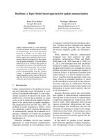
subtle, as shown in Figure 1.1.
So we want to find two contour extraction methods. One method is semiautomatic and very accurate, which is for the surgery system. The other method
is fully automatic but less accurate, which is for the screening system.
3
Figure 1.1: An example of subtle fracture.
1.2
Research Goal
The objective of this research is to extract the contours of the left femur and the
right femur from a hip x-ray image. An example of the standard hip x-ray image
is shown in Figure 1.2. The position, size and orientation of the femurs in all
the input images are similar but not exactly the same. The ideal result will be
a curve, consisting of a series of points, which coincides with the contour of the
femur. An example of the desired result is shown in Figure 1.3.
In Figure 1.4, a typical example of the femur cropped from the hip x-ray image
is shown. It can be seen that the image is generally very noisy. A lot of edges
caused by the muscles or other bones can easily mislead the contour extraction
algorithm. For example, the femoral head overlaps the pelvic bone, which makes it
very difficult to get a clear contour of the head. The edge caused by the abdominal
muscle, which usually passes the femur, and the muscles around the shaft can also
mislead the algorithm. These extraneous edges and noise make fully automatic
4
Figure 1.2: An example of the hip x-ray image.
Figure 1.3: An example of the extracted femur contour.
5
Figure 1.4: A typical femur x-ray image.
contour extraction very difficult.
A common way to avoid the noise is to initialize the model contour very near to
the true contour. In existing x-ray image analysis applications, there are generally
two initialization approaches. The first approach is manual initialization, which
requires the user to input the initial contour. For example, in [LZYZ04], the
system requires the user to provide the rough initial position of the target carpal
bone, which is then deformed to get the true contour of the carpal bone, as shown
in Figure 1.5. Generally, user input can make the problem easier to solve. But it
makes the system not fully automatic.
Another approach is to automatically find the initial contour by some heuristic
conditions. Normally, these heuristic conditions are obtained from prior knowledge
6
of the target object, which is different for different object. For example, in [CJ04],
the system tries to detect the gap between neighboring teeth and the gum line
to form the initial contour of the tooth, as shown in Figure 1.6. In this way,
the system can be fully automatic, but the accuracy of the result will highly
depend on the detection result of the initial contour, which is affected by the
target object and the input image. Moreover, the heuristic conditions make the
system applicable only to specific body parts.
In general, fully automatic contour extraction of target objects with complex
shapes from noisy images is a very difficult problem. In the system presented in
this thesis, both approaches are implemented. The manual initialization approach
can be used in situations where reliability and accuracy are very important and
automation is not crucial. The automatic initialization approach can be used
where the process must be automatic and a small amount of error can be tolerated.
1.3
Thesis Overview
The general outline of this thesis is as follows: Chapter 2 will introduce some
related work. Chapter 3 will discuss the method of femur contour extraction with
some minimal manual initialization. Chapter 4 will discuss the method of fully
automatic femur contour extraction. And finally, Chapter 5 will discuss future
work and Chapter 6 will conclude this thesis.
7
Figure 1.5: Carpal bone segmentation. (a) initial contour (b) final result (Figure
4 from [LZYZ04]).
Figure 1.6: Tooth contour initialization (Figure 4 from [CJ04]).
8
Chapter 2
Related Work
Existing object contour extraction methods for medical images can be categorized
into four general categories: segmentation, contour following, deformable models
and atlas-based. These approaches are discussed in more details in the following
sections.
2.1
Classical Segmentation Approach
Image segmentation and contour extraction are related in the sense that if an object is segmented from the image, then the contour of the object is available, and
vice versa. But there are still some differences between segmentation and contour
extraction under certain conditions. For example, classical image segmentation
algorithms assume that the regions to be segmented contain homogeneous features so they attempt to segment an input image into regions based on feature
homogeneity criteria. But contour extraction algorithms attempt to extract the
contours of complete objects. If the target objects contain several regions with
9
different features, the results of image segmentation and contour extraction will
be different.
Image segmentation has been studied from a wide variety of perspectives.
Lots of techniques have been proposed, including edge detection [Can86, Per80,
Pra80], thresholding [LHKU98, LKC+ 95, SSW88], region growing and splitting
[AB94, BJ88, DMS99, HS85], clustering [Cel90, Sch93, PB00, PHB99], watershed [GMA+ 04, RM00, Ser82], and classification [MFTM01, RM03, KGKW98,
WGKJ96] etc. These methods have been applied for segmenting medical images
into regions with homogeneous features such as brain [GDP+ 98, LHKU98] and
tumor [GBBH96, PPO+ 96, LKC+ 95] in MR [BHC93, KGKW98] or CT [LS92]
images.
However, these classical segmentation algorithms are not applicable to the
extraction of femur contours in x-ray images because the homogeneity criteria are
not satisfied for femurs in x-ray images. For instance, in a femur x-ray image, the
femoral head region contains nonuniform texture pattern due to the trabeculae
(Figure 2.1), and the femoral shaft region has nonuniform intensity due to the
hollow interior within solid bony walls (Figure 1.4). Moreover, the femoral head
overlaps with the pelvis bone (Figure 1.4). In this case, the extraction of femur
contours becomes a more complex problem than classical image segmentation
problem.
10
Figure 2.1: Close-up view of femoral head.
2.2
Contour Following Approach
Contour following is the most direct and intuitive approach, which is widely used in
many applications [LNOK01, ZTMR01, LNY00, BC99, CHV+ 97]. The basic idea
is to select corners and local edge maxima as starting points, and then to follow
a contour to another corner or local edge maximum by selecting the strongest
edge in the following process. For example, Lourens et al. used this approach to
extract contours from color images [LNOK01]. First of all, the image contrast is
enhanced, and then the edge and corner points are detected. After that, a greedy
contour following process is started from the edge and corner points. At the corner
points, more than one contour can be followed. In the contour following process,
a contour is always passing through the local gradient maximum. But in this
approach, the contour following process can be easily misled by undesired edges.
As discussed in the previous chapter, the femur x-ray images are very noisy. It is
very difficult to control the contour following algorithm to always pick the right
edges.
11
2.3
Deformable Model Approach
Deformable model approach is to let the model of the target object deform under
certain constraints and finally snap onto the contour of the target object. Some
commonly used methods in this approach include active contour, active shape and
level set method.
2.3.1
Active Contour
Active contour [KWT88, TPBF87, TWK88], or snake, method deforms the initial
contour by minimizing the total energy of the contour. Three kinds of energy
terms can be defined in active contour:
1. Internal energy, which constrains the stretching and bending of the contour.
2. Image force, which is the image feature such as image intensity or edges
attracting the contour.
3. External force, which constrains the deformation of the contour.
The external force can be absent, and then the deformation of the model is only
affected by the image features, which makes the model very sensitive to noise and
its initial configuration. An example of extraction of carpal bone contours using
active contour is shown in Figure 1.5.
A lot of improvements to the snake have been proposed. For example, Xu et
al. suggested using gradient vector flow (GVF) as the image force to make the
snake less sensitive to its initial configuration and capable of snapping to concave
object boundaries [XP97]. Some other methods incorporate geometric constraints
12
in the snake. For example, Shen et al. [SHD01] embedded geometric information
as attribute vector into the snake. The attribute vector contains the areas of
triangles formed by each point on the snake and their two neighboring points.
During the snake’s evolution process, the areas of the triangles are constrained.
Foulonneau et al. [FCH03] includes Legendre moments in the snake to provide
global description of a reference shape.
Active contour method has been used for segmentation of brain in MR images [AM00], liver [GKK98, YF03] or heart [SHC94] in CT images, and blood
vessels [XSK+ 94] in HVEM images. In general, the active contour method is still
very sensitive to noise and requires good initialization. And snake cannot handle
topology change.
2.3.2
Active Shape
Basically, active shape model (ASM) [CHTH94] is a statistical model generated
from a set of training samples. A series of corresponding points, called landmark
points, are identified on the boundary of the target object in each training image.
Then the training samples are regarded as vectors and statistical parameters of
the vector distributions are computed using principal component analysis. By
changing the parameters, new shapes can be synthesized.
The contour extraction process using ASM is actually a process of synthesizing
an optimal shape that is most similar to the shape in the image. The statistical
difference between the synthesized shape and the original model can be calculated.
By restricting the difference to small values, the deformation can be limited to
13
Figure 2.2: Extraction of tibia contour using ASM. The labelled points 1, 2, 3 are
landmarks
an acceptable range. An example of extraction of tibia contour from ultrasound
images using ASM is shown in Figure 2.2.
ASM has been applied for segmentation of tibia bone in ultrasound images
[HZ01], heart in echocardiographic images [HG00] or MR images [OBHF03], and
vertebra in CT images [STA96]. ASM is more suitable for the situation where
the shape of the target object can be controlled by not too many parameters.
Otherwise it will be too difficult to synthesize the optimal shape. Moreover,
many training samples are needed to correctly compute compute the statistical
distribution.
2.3.3
Level Set
The level set method is proposed by Sethian et al. [Set96]. The idea of this method
is to handle the topology change problem in one higher dimension. Let Γ denote
a closed 2D curve. To deform Γ, a 3D function φ(x, y, t) is defined. This is called
14