Modeling and optimization for an air cargo terminal
Bạn đang xem bản rút gọn của tài liệu. Xem và tải ngay bản đầy đủ của tài liệu tại đây (868.5 KB, 120 trang )
MODELING AND OPTIMIZATON
FOR AN AIR CARGO TERMINAL
HUANG PENG
(B. Eng., Tsinghua University)
A THESIS SUBMITTED
FOR THE DEGREE OF MASTER OF ENGINEERING
DEPARTMENT OF INDUSTRIAL AND SYSTEMS ENGINEERING
NATIONAL UNIVERSITY OF SINGAPORE
2005
Acknowledgements
I would like to express my deep and sincere gratitude to my supervisor, Prof. Huang
Huei Chuen. Her wide knowledge and her logical way of thinking have been of great
value for me. Her invaluable advice, guidance and patience throughout my study and
research have made the completion of this work possible.
I am deeply grateful to my supervisor, Dr. Lee Loo Hay, for his detailed and
constructive comments, as well as his understanding, encouraging and personal
guidance. I wish to thank him for his stimulating suggestions and kind encouragements
which have helped me during all the time of research for and writing of this thesis.
I owe my most sincere gratitude to Prof. Ellis Johnson, Prof. Chew Ek Peng, Dr. Lee
Chul Ung, Dr. Wikrom Jaruphongsa and other professors in my departments, who
gave me the opportunity to work with them in the air cargo research group. Their
valuable advice and friendly support have been very helpful for my research.
My warmest thanks also go to the colleagues and fellows in my department. They are
Dr. Bao Jie, Dr. Cheong Wee Tat, Chen Gang, Dr. Dai Yuanshun, Gao Wei, Dr. Paul
Goldsman, Jiang Feng, Lai Xin, Leong Chun How, Liang Zhe, Liu Bin, Dr. Ivy Mok,
Dr. Alec Morton, Dr. Sun Gang, Dr. Tang Yong, Wang Xiaoyang, Wang Wei, Dr.
Yang Guiyu, Xu Zhiyong, Zhang Caiwen, Zeng Yifeng, to name a few (alphabetically).
Finally, my gratitude is due to my family for their encouragement, help, support, and
understanding throughout my study and research.
i
Table of Contents
Acknowledgements.......................................................................................................... i
Table of Contents............................................................................................................ii
Summary ......................................................................................................................... v
List of Tables ................................................................................................................vii
List of Figures ..............................................................................................................viii
1
2
3
Introduction............................................................................................................. 1
1.1
Background ..................................................................................................... 2
1.2
Introduction on air cargo terminal .................................................................. 5
1.3
Introduction on the cargo inbound process of an air cargo terminal .............. 8
1.4
Introduction on the tactical planning of an air cargo inbound terminal........ 12
1.5
Problem description ...................................................................................... 14
1.5.1
Motive of the research project .............................................................. 14
1.5.2
Performance measures .......................................................................... 15
1.6
Research contributions.................................................................................. 16
1.7
Organization of the thesis ............................................................................. 17
Literature Review.................................................................................................. 20
2.1
Container terminal operations....................................................................... 20
2.2
Freight terminal strategic planning ............................................................... 23
2.3
Load balancing.............................................................................................. 25
Mathematical Formulation.................................................................................... 29
3.1
The mixed-integer programming model ....................................................... 29
3.1.1
Assumptions.......................................................................................... 30
3.1.2
Model formulation ................................................................................ 32
ii
3.1.3
3.2
Model description ................................................................................. 37
4
The estimation of the coefficients................................................................. 41
3.2.1
Estimate of the times............................................................................. 43
3.2.2
Estimate of the workload coefficients................................................... 44
3.2.3
Data information for estimate ............................................................... 47
Simulation Modeling ............................................................................................ 48
4.1
Simulation model design............................................................................... 48
4.1.1
Model description ................................................................................. 52
4.1.2
Rule and policy description .................................................................. 60
4.1.3
Input parameters.................................................................................... 63
4.1.4
Performance measure............................................................................ 64
4.1.5
Model Implementation.......................................................................... 65
4.2
Verification of the model .............................................................................. 69
4.3
Simulation setups and pilot runs ................................................................... 71
4.3.1
Simulation run design ........................................................................... 71
4.3.2
Pilot runs for one-day simulation.......................................................... 74
4.4
5
Validation of the model ................................................................................ 77
Solution and Result Presentations......................................................................... 82
5.1
Optimization procedures ............................................................................... 82
5.2
Results and outputs for the one-day problem ............................................... 85
5.2.1
MIP solution results for the one-day problem ...................................... 85
5.2.2
Simulation outputs for the one-day problem ........................................ 89
5.2.3
Comments ............................................................................................. 91
5.3
5.3.1
Results and outputs for the one-week problem............................................. 93
MIP solution results for the one-week problem.................................... 93
iii
5.3.2
Simulation outputs for the one-week problem...................................... 98
5.3.3
Comments ........................................................................................... 100
5.4
6
Conclusion .................................................................................................. 102
Conclusions and Future Research....................................................................... 105
6.1
Conclusions................................................................................................. 105
6.2
Future Research .......................................................................................... 107
Bibliography ............................................................................................................... 109
iv
Summary
This research work studies the modeling and optimization for an air cargo inbound
terminal. Operations in the terminal include cargo receiving, checking-packing, orderpicking, and shipping. There are many factors that affect the operation performances in
the terminal. The factors investigated in this thesis are the cargo flow time, workload
balancing, and congestion effects. To address these factors, a cargo assignment plan is
studied in detail.
Because of the various factors of consideration for this problem, it is neither possible
to be formulated as a single objective problem, nor practicable to be modeled as a
linear programming or integer programming problem, given the existing modeling
techniques. Therefore a multi-objective mixed-integer programming model is
formulated to improve the assignment plan. It aims to provide a series of nondominated solutions.
These solutions are then input to a simulation framework which will identify the best
solution(s) to the preference of the decision maker. This simulation is able to model
the cargo handling operations. It not only evaluates the effects of cargo assignment on
the overall performance, but also examines the congestion effects due to imbalanced
assignment and system randomness. The performances of these solutions in simulation
are collected and compared for decision making.
Such a research approach including MIP formulation and simulation modeling is
applied to an inbound air cargo terminal. Extensive computational experiments are
v
conducted with actual data as the input sources. This approach is demonstrated to be
capable to support the decision makings for the terminal.
vi
List of Tables
Table 4.1 Sample size of each hypothesis test............................................................. 80
Table 4.2 p-value of each hypothesis test .................................................................... 80
Table 5.1 Experiment designs...................................................................................... 84
Table 5.2 Extreme values of each objective (one-day)................................................ 86
Table 5.3 The values of constraints for each setting (one-day) ................................... 86
Table 5.4 Solution results of each objective for each solution (one-day).................... 87
Table 5.5 Simulation result statistics for one-day problem ......................................... 90
Table 5.6 Extreme values of each objective (one-week) ............................................. 94
Table 5.7 The values of constraints for each setting (one-week) ................................ 94
Table 5.8 Solution results of each objective for each solution (one-week) ................. 96
Table 5.9 Simulation result statistics for one-week problem....................................... 99
Table 5.10 The comparison between one-day and one-week problems .................... 103
vii
List of Figures
Figure 1.1 Cargo flow process in this inbound terminal................................................ 3
Figure 1.2 A simple illustration of the basic layout for a terminal ................................ 6
Figure 1.3 Cargo movement process for inbound operations ........................................ 9
Figure 1.4 General flow of a ULD............................................................................... 10
Figure 3.1 The workload profile of a flight ................................................................. 43
Figure 4.1 The simulation model framework .............................................................. 49
Figure 4.2 An illustration of simulation layout............................................................ 49
Figure 4.3 General flow of ULD movements .............................................................. 53
Figure 4.4 Flow chart of the ULD movement at the first group of ramp zones .......... 55
Figure 4.5 Flow chart of the ULD movement at the second group of ramp zones...... 58
Figure 4.6 Sample layout of simulation model ............................................................ 68
Figure 4.7 Sample average of replication runs (one-day)............................................ 75
Figure 4.8 Moving average of replication runs (one-day, window size = 2)............... 76
Figure 4.9 Moving average of replication runs(one-day, window size = 10).............. 76
Figure 4.10 Three steps for validation ......................................................................... 77
Figure 5.1 Comparisons for simulation results (one-day) ........................................... 93
Figure 5.2 Comparisons for simulation results (one-week)....................................... 101
viii
Chapter 1 Introduction
1 Introduction
Since the momentous globalization of world trading and economy, the airline industry
has been playing a pivotal role in the integration of world markets. Along with the
growing demands of international trading and exchange, global air transportation is
experiencing an excellent opportunity to boom again after the 911 incident and the
global economic recession in 2001. With the paces of globalization and regionalization,
the world is marching towards a new phase of peaceful development. The recent trend
in financial integration and energy market liberalization further stimulate the up-stream
supply for the airline industry. Evidence suggested that the airline industry is soaring
again despite the recent events like epidemics and turbulence in the Gulf. A robust
global supply chain network is shaping itself to accommodate the start of another
economic growth cycle. Airline industry is therefore becoming more and more crucial
in the global supply chain.
Air cargo terminal connects different modes of shipment together, and therefore serves
as a significant and indispensable link in the global commerce chain. Recent advances
in information technology and computer hardware pave the way for possible
improvement on the air cargo terminal’s strategic and tactical performance.
This research is motivated by a study at an air cargo terminal which handles the
inbound and transshipment cargos for a top-tier international airline at its hub airport.
We observe that cargos shipped by the airline arrive at the terminal in the form of a
pallet or a Unit Load Device (ULD) which often consists of a few consignments
belonging to different cargo agents. (Generally, cargo agent is used by the cargo
1
Chapter 1 Introduction
terminal to address all the shippers, freight forwarders, and consignees that have
consignments handled by the cargo terminal.) In addition, the concerned airport may
not be the intended destination for some of the consignments.
This chapter aims to explain the related backgrounds about the research project. It thus
starts with a brief introduction about the background of the research, followed by the
detailed description on the function and layout of an inbound cargo terminal.
Subsequently, the cargo inbound handling process and its related assignment planning
approach are introduced to give some lights on the origination of the research problems.
After the descriptions about the research motives, the contribution of this research
work is briefed. Finally, the structure of this entire thesis is outlined in details.
1.1 Background
This section provides an overview of the research problem. It gives an overall
understanding about where the problem comes from, how the problem is related to our
research, and how we elaborate it in the future. The general description in the thesis is
based on our observations at a leading international airport.
An air cargo terminal is essentially a fast-moving warehouse. The inbound terminal
needs to do breakbulking in order to facilitate cargo agents’ collections and to transfer
the cargos to the outbound terminal for further processes to be ready for the connecting
flights. In an inbound terminal, the cargos are moved through various facilities, and
finally reach the outbound terminal or shipment dock. The cargo travels within the
2
Chapter 1 Introduction
terminal via different types of facilities and transferring equipments. The details about
the cargo terminal will be introduced in Section 1.2.
Due to the varied cargo characteristics, the cargo movement in the terminal exhibits
different patterns. The cargo airplanes touch grounds at the airfield within the airport.
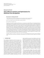
As we can see in Figure 1.1, after the cargos are unloaded from the airplane and towed
to the ramp side of terminal, the cargos start their movement within the terminal.
Unloading &
towing to terminal
Airfield
PCHS
storage
Outbound terminal
Ramp
Inbound
Terminal
Breakbulk
workstation
Figure 1.1 Cargo flow process in this inbound terminal
It is obvious to see from Figure 1.1 that there are two directions for the cargos to travel
within the terminal. One of the directions is to transfer to the outbound terminal
immediately after they arrive at the inbound terminal or through the intermediate
storage (PCHS storage, more details in Section 1.2) to the outbound terminal. This
direction is for transshipment cargos which need to be sent to the connecting flights.
The other cargo movement is to transfer them to the breakbulk workstation where they
are broken loose at the breakbulk workstation (more details in Section 1.2) in
anticipation of the collection from cargo agents. The process of the inbound cargo
handling will be further introduced in Section 1.3.
3
Chapter 1 Introduction
In order to handle huge volume of cargos, the terminal is equipped with multiple
facilities and equipments. These facilities include the ramps, storage places, and
breakbulk workstations. The ramps are divided into several ramp zones for the ease of
management. They are the places to receive the inbound cargo. The storage places in
the PCHS (Pallet Container Holding System) and the breakbulk workstations are also
grouped into clusters. The breakbulk workstations are where the breakbulk job is
taking place. The equipments within the PCHS are the hoists and the transferring
vehicles which assist the cargo movements. It is observed that the transferring time
between different facilities vary and some equipments are shared between groups.
Since there are multiple ramp zones and breakbulk workstation areas in the terminal,
the present work practice for this international airline is to designate the suitable ramp
zone and the workstation area for each flight according to their flight number.
Therefore a fixed assignment plan which dictates the ramp zones, workstation areas,
and the storage places belonging to a particular flight is adopted. A more
comprehensive introduction about the cargo assignment planning is given in the
upcoming Section 1.4.
Such a fixed assignment plan would make it easy for the management of cargo
dispatching. In addition, since the transferring time between different facilities varies,
it helps to choose the shorter traveling path to take advantage of this difference.
Furthermore, a fixed assignment makes it possible to estimate the workload condition
for each facility, since the flights allocated to each facility are already known
4
Chapter 1 Introduction
beforehand. It is therefore obvious that the efficiency of the terminal operations
depends much on the quality of this assignment.
Our research is to measure and identify a good assignment for the terminal operation
so as to improve its efficiency. In the following sections, more detailed introductions
about the terminal operations, function, layout, cargo handling process, and cargo
dispatching planning are described to elicit our research motivations and its
performance measures. After the necessary background information, the contributions
of this work and the structure of the thesis are discussed.
1.2 Introduction on air cargo terminal
The purpose of this section is to give some basic description about the function,
components, and layout of an air cargo inbound terminal.
The basic layout of the inbound cargo terminal can be illustrated by the graph below in
Figure 1.2. It primarily consists of ramp zone facilities, PCHS system, and breakbulk
workstation areas.
5
Chapter 1 Introduction
Ramp zone #2
Ramp zone #4
……
Ramp zone #n
Ramp zone #1
Ramp zone #3
……
Ramp zone #n-1
PCHS system (with transferring vehicles and storage spaces inside)
Breakbulk workstation area #1
(Contains a group of
workstations)
……
Breakbulk workstation area #n
(Contains a group of
workstations)
Figure 1.2 A simple illustration of the basic layout for a terminal
The air cargo in movement is packaged in a unit load device (ULD). It is important to
firstly explain the basic layout of the terminal and the structure of the cargo handling
system in a detail manner to build an understanding of the air cargo inbound terminal.
The cargo terminal is essentially a multi-level warehouse building. The inbound and
outbound functions of the terminal are differentiated and there are dedicated subterminals to serve either the inbound or outbound function.
A PCHS is the same concept as a MHS (Material Handling System), which can hold
the cargo for short time on-purpose storage.
A ramp zone is the receiving dock of the inbound terminal for the cargo unloaded from
the airplane. Once a ULD is towed from the airside of the airport to the terminal, the
ULD will be introduced into the ramp zone. There are multiple ramp zones located at
different areas of the terminal. Ramp zones are located at the ground level of the
terminal building. The cargo is placed onto the conveyor queue lane of the ramp zone
6
Chapter 1 Introduction
after they arrive at the terminal. From the queue lane, the cargo is thereby transferred
into the PCHS by the transferring vehicles.
The transferring vehicle is also referred as the ETV. ETVs are electrically driven
equipments within the PCHS which are controlled by the computerized control system.
These vehicles move along the vehicle channels within the PCHS. It is comparable to
the AGV (Automated Guided Vehicle) of an ASRS (Automated Storage / Retrieval
System). The transferring vehicles serve various purposes such as moving the cargo
between the queue lane and PCHS, transporting cargo between different positions
within the PCHS, and transferring cargo between the PCHS storage positions and exit
positions of the PCHS.
The ultimate purpose of the inbound cargo terminal is to move the cargo to the
outbound terminal or to the breakbulk workstation. The cargo goes to the outbound
terminal may be checked and palletized again for another flight in the outbound
terminal. The breakbulk workstation performs the breakbulk job for the palletized
cargo.
PCHS highway serves as the direct linkage between the inbound terminal and the
outbound terminal. The inbound cargo with transshipment purpose and without
breakbulk requirement will be moved directly via this direct link to the outbound
terminal. This PCHS highway locates horizontally in the space above the ramp zones.
7
Chapter 1 Introduction
Hoist serves as the linkage between different levels of the terminal. A hoist is an
electricity-driven lift for the purpose of moving cargoes vertically between different
levels. It has fixed capacity so that it could carry fixed amount of ULDs each time.
Breakbulk workstations locate outside the PCHS and near the exit dock of the terminal
warehouse building. These workstations are grouped into several areas to ease the
management and resource dispatching. These areas are called the breakbulk
workstation areas. At each workstation, the checking team performs the breakbulk job
according to an eight-hours-per-shift schedule. The palletized cargos are broken loose
and rearranged, and then moved by forklift to the outbound terminal or the receiving
dock for the cargo agents’ collection.
1.3 Introduction on the cargo inbound process of an air cargo
terminal
In this section, we address the cargo inbound handling process in a thorough way. The
cargo inbound process is the subject of our study, and the purpose of this study is to
improve the process via our modeling and simulation approach.
An illustration of the process is given in Figure 1.3 for an incoming flight from the
time it arrives at the airport to the time it leaves the breakbulk workstation in the
inbound terminal. Obviously, this chart doesn’t consider the case of direct
transshipment of which the cargo moves from PCHS to the outbound terminal directly.
Since the ULDs of a flight arrive on a unit-by-unit basis, it is possible that when the
first ULD is being processed at the next process, the last ULD could be still at the
8
Chapter 1 Introduction
initial process. Therefore, there is some overlapping between the time frames of two
adjacent processes in the chart.
Cargo towing
Ramp zone
processing
PCHS storage
Breakbulk area
processing
t
Figure 1.3 Cargo movement process for inbound operations
Due to the fact that there are multiple ramp zones and breakbulk workstations, it is
necessary to decide the allocation of these facility resources to the cargo beforehand.
The cargo dispatching procedure follows the planned assignment to assign the cargos
from different flights to different facilities. Thus, this cargo dispatch plan is a tactical
planning problem of assigning flights to ramp zones and to breakbulk workstation
areas.
As mentioned before, there are various cargo flow patterns within the cargo terminal.
Hence, the different sequences of cargo flow need to be introduced in further detail.
The general cargo flow process can be broken down according to its associated origindestination. The following flow chart mainly describes the cargo flow process of
inbound cargo operations.
9
Chapter 1 Introduction
Flight arrival
Check the preplanning to verify the destination ramp for each flight
ULD arrival at ramp & confirm the destination break bulk
Which cargo
type?
Mixed cargo
Direct transshipment
Move using ETV
Move using ETV
Move via PCHS
Highway linked to
Move to outbound
terminal
Workstation
buffer is full
N
Y
Move to PCHS
temporarily storage
locations & wait until
workstation buffer is
not full
Move using ETV
Move to workstation
Move to workstation
Enter workstation and
breakbulk
Enter workstation and
breakbulk
Move to outbound
terminal or
Exit the terminal
Move to outbound
terminal or
Exit the terminal
Figure 1.4 General flow of a ULD
10
Chapter 1 Introduction
The cargo flow process shown in the dashed box is solely decided by its own origin
and destination positions. All the movements included in this dashed box are the sub
flow process of the ULD movement within the PCHS.
The cargo flow process in the dashed box involves the choice of different paths within
the PCHS based on the cargo characteristics. As mentioned in Section 1.1, different
cargo characteristics, such as mixed shipment, or direct transshipment can determine
how the cargo moves within the PCHS system. This can be seen from the decision
making on whether to use the PCHS highway to move the direct transshipment cargo.
If the cargo is for direct transshipment purpose, it will be lifted onto PCHS highway
through which the cargo will reach the outbound terminal. Otherwise, the cargo will be
moved into PCHS for breakbulk purpose.
The cargo flow process of the mixed cargo is more complicated. The mixed cargo
includes both the imported cargo which needs breakbulk before exports and the cargo
which requires import transactions only. The choice of whether to use the temporary
storage space is also of our interest here. As a generally accepted practice, it is more
preferable for the cargo to travel through the shorter and less congested path if this
proposed path is free to use. Otherwise, if the shorter path were not available due to
congestion or malfunction, the cargo would stay in the storage temporarily. When the
path becomes available once more, the cargo movement will start again. The mixed
cargo will be eventually moved to the outbound terminal or breakbulk workstations.
11
Chapter 1 Introduction
1.4 Introduction on the tactical planning of an air cargo inbound
terminal
It is mentioned in Section 1.3 that the cargo dispatch planning is a problem of
allocating cargos to different facilities during different time frames. In this section, we
try to explore the outcomes of such a planning, as well as the relationships between the
tactical planning of the cargo dispatching and the operation efficiency and service
quality of the terminal.
It is discovered that the preplanning of the assignment of flights to different ramp
zones and then to different workstation areas could affect the ULD’s flow pattern and
in turn, influences the facility utilization and overall throughput time. The capacity
utilization becomes the main concern for the improvement of handling efficiency. Plus,
as a service provider, the terminal serves as the linking node between the carriers and
the cargo agents. It is therefore crucial to improve the quality of service by reducing
the overall throughput time within the terminal. Thus, the operation efficiency and
service quality of the cargo terminal are heavily dependent on the preplanning
assignment.
We observe currently, in this inbound terminal, some of the ULDs need to travel
relatively longer distance to reach their assigned areas. Many transshipment cargos are
assigned to travel through an unreasonable longer way to the outbound terminal
instead of some shorter path. In addition, the handling volumes of the workload at
different workstation areas are imbalanced. One of the possible reasons for these
12
Chapter 1 Introduction
observations is the imbalanced assignment of flights to the ramp zones and the
workstation areas.
It appears that the current system does not operate at the ideal level due to its
assignment planning. Such similar problems also exist elsewhere in air freight or sea
freight terminals. The current inefficiencies of the terminal operations are mainly as
follows:
1. Imbalanced workload and congestion
The data we collected show that, different segments of the ramp zones handle different
workloads resulting some of the equipments highly utilized while others under utilized.
In other words, during certain hours, the highly utilized ramp zone would suffer from
ULD congestion on the ramp queue lane, waiting for the ETV. The imbalanced
workload creates the problem of congestion, and the congestion at the ramp queue lane
causes the longer time to handle these congested cargos.
In the current practice, the cargos are staged at the PCHS locations which are close to
the workstation for a short duration of no more than 60 minutes before transferring to
breakbulk workstation. The reason is that the cargos have to wait for the workstation to
be free, i.e., when the workstation reaches its capacity limit, the cargos need to be
stored at the PCHS temporarily.
13
Chapter 1 Introduction
2. Inefficient ULD flow
Since the mixed cargos need to be directed to the breakbulk workstations for the next
stage operation, they will make use of the transferring equipments within the PCHS to
reach the designated workstations.
It is observed that some of the not-so-good ULD flows within the PCHS use more
equipment and take longer time unnecessarily because of their long traveling paths,
even though there are multiple available paths with no congestions to go. Such detours
cause the cargo flow in the terminal suffering from long movement time.
1.5 Problem description
After some piloting collection and analysis of the data, the findings based on the
analysis suggest that the current fixed assignment of flights to different ramp zones
and to different workstation areas is not efficient. Therefore, it would be necessary to
revise the preplanning assignment in order to improve the cargo flow pattern. It
appears that the current system does not operate at the maximum efficiency level due
to the current assignment planning.
1.5.1
Motive of the research project
For a busy facility with certain peak periods such as an air cargo terminal under the
dynamic condition, congestion reduction and diffusion are equally important. The
ULD might encounter longer flow time by traveling through a congested shorter path
14
Chapter 1 Introduction
than through the longer but less congested paths. Hence, this research project is
expected to bring shorter flow time and less congestion to this cargo terminal.
The aim of the project is to optimally allocate the incoming cargos from different
flights to the ramp zones and to the workstation areas so as to improve the material
flow in the cargo terminal. It plans to reduce the movement time for cargo to move
from ramp to PCHS locations, export terminal, and breakbulk workstations, along with
the consideration that the congestion effects can be lessen. In other words, the model
aims to find a flight-to-ramp-to-workstation assignment, to reduce the flow time and to
streamline the cargo flow.
1.5.2
Performance measures
The objective of this problem is to improve the quality of cargo assignment to reduce
the congestion occurred due to imbalanced workload while not compromising on the
flow time. The flow time reduction problem is the most straightforward issue for the
cargo terminal, while the congestion problem and the imbalanced workload problem
arose from our observations and insights derived from the initial stage data analysis.
There are three performance measurements proposed for this study:
1. The average flow time of the ULD is one of the most straightforward measures for
evaluating the system efficiency. The flow time in terms of an ULD normally is made
up of movement time and processing / queuing time. i.e., flow time = movement time
+ processing / queuing time. The long storage time could be the result of other reasons
15
Chapter 1 Introduction
such as the delay in paperwork or late notification for the customers, rather than
congestion. Here the term flow time will not consider the long intermediate storage
time resulted from the above reasons.
2. To avoid the imbalanced assignment of the workload at the ramp zones and the
workstation areas, we use the maximal pair-wise difference of the capacity ratio as the
second measure. We approximate the degree of workload congestion by the capacity
ratio. The capacity ratio is the ratio of the current assigned workload at the equipment
to the nominal processing capacity of the equipment during a fixed time unit. The
capacity ratio (CR for short) should be less than 1 in reality, but may be greater than 1
if it is calculated in a relaxed manner by including works waiting in queue. Therefore
the capacity ratio is a measure of the utilization of each facility.
3. In order to measure the seriousness of the congestion, we suggest the exceeding
value of the capacity ratio over 1 as the third measure. If taking into account the
possible over-utilization at some facilities, the capacity ratios at these facilities would
be greater than 1 during some intervals. To avoid such risk of over-utilization, it is
therefore valuable to reduce the overall exceeding values of capacity ratios.
1.6 Research contributions
This thesis tackles the operations enhancement plan in an air cargo inbound terminal.
The research work suggests a novel and comprehensive approach to address the flightto-ramp-to-workstation assignment problem. The main contributions are:
16