Moment of inertia and torque performance sensorless measurement for HDD used spindle motors
Bạn đang xem bản rút gọn của tài liệu. Xem và tải ngay bản đầy đủ của tài liệu tại đây (2.52 MB, 125 trang )
Moment of Inertia and Torque Performance
Sensorless Measurement for HDD Used Spindle Motors
HUANG RUO YU
NATIONAL UNIVERSITY OF SINGAPORE
2004
Moment of Inertia and Torque Performance
Sensorless Measurement for HDD Used Spindle Motors
HUANG RUO YU
(B.Eng. Shanghai Jiaotong University)
A THESIS SUBMITTED
FOR THE DEGREE OF MASTER OF ENGINEERING
DEPARTMENT OF ELECTRICAL AND COMPUTER ENGINEERING
NATIONAL UNIVERSITY OF SINGAPORE
2004
Acknowledgement
Although this thesis is written by me, I could have not accomplished it if I were doing
researches on my own. Here I would like to express my sincere gratitude to the
guidance given by my supervisors and help from my colleagues. Thanks to the
splendid idea conceived by Dr. Bi Chao, the entire process of the moment of inertia
and torque constant measurement is feasible. Moreover, I would like to thank him for
consistent assistance during my entire progress of the experiment and thesis writing.
Also, I am very appreciated by the instructions given by Dr. Jiang Quan when I was
doing the experiment. Finally, I would like to thank for my family for the support in
my mind and anyone who once helped me in my research work. It is your help that
makes the embodiment of this thesis feasible.
Contents
Table of Contents
1.
2.
3.
4.
Introduction ........................................................................................................................... - 1 1.1.
Motivation of the work .......................................................................................... - 1 1.2.
Scope Definition.................................................................................................... - 2 1.3.
Organization of the thesis ...................................................................................... - 3 Literature Review .................................................................................................................. - 5 2.1.
Torque Constant Measurement .............................................................................. - 5 2.2.
Moment of Inertia Measurement ........................................................................... - 8 2.2.1.
Conventional Method for Inertia Measurement........................................... - 10
Calculation Method............................................................................ - 10
Torsional Vibration Method ............................................................... - 12
Pendulum Method .............................................................................. - 14
Falling Weight and Pulley Method..................................................... - 16
Mechanical Time Constant Method ................................................... - 17
Parameter Identification..................................................................... - 18 2.2.2.
Prerequisites in HDD industry..................................................................... - 18 2.2.3.
Other Method............................................................................................... - 20 2.3.
Speed Measurement and Optimal Spline............................................................. - 21 Digital Fitter and Optimal Spline ........................................................................................ - 26 3.1.
Speed Pattern ....................................................................................................... - 26 3.2.
Fitter Analysis...................................................................................................... - 27 3.2.1.
Fitter Requirements ..................................................................................... - 28 3.2.2.
Speed Data Pattern ...................................................................................... - 28 3.2.3.
Cubic Spline Interpolation........................................................................... - 29 3.2.4.
Interpolation Limitations ............................................................................. - 33 3.3.
Optimal Spline Algorithm ................................................................................... - 34 3.3.1.
Algorithm Development .............................................................................. - 35 3.3.1.1. Segmentation...................................................................................... - 36 3.3.1.2. Optimization and Spline Interpolation ............................................... - 37 3.3.1.3. Linear System Solving ....................................................................... - 40 3.3.2.
Algorithm Logic Diagram ........................................................................... - 42 3.3.3.
Algorithm Analytical Results ...................................................................... - 43 3.3.3.1. Simulation on the Sinusoid Function ................................................. - 44 3.3.3.2. Simulation on Exponential Function.................................................. - 46 Torque Constant & Back-EMF Constant............................................................................. - 50 4.1.
Introduction ......................................................................................................... - 50 4.2.
Principle Description ........................................................................................... - 51 4.2.1.
Driving Circuit............................................................................................. - 51 4.2.2.
Back-EMF Signal Waveform....................................................................... - 54 4.2.3.
Ke Calculation Algorithm ............................................................................ - 57 4.2.3.1. Proposed Algorithm ........................................................................... - 58 4.2.3.2. Influence of Harmonics Component .................................................. - 58 4.2.3.3. Speed Changing Trends ..................................................................... - 60 -
I
Contents
4.3.
Practical Implementation..................................................................................... - 64 4.4.
Test Results.......................................................................................................... - 66 5. Inertia Measurement............................................................................................................ - 70 5.1.
Introduction ......................................................................................................... - 70 5.2.
Measurement Algorithm Development................................................................ - 71 5.2.1.
Basic Calculation Equations........................................................................ - 71 5.2.2.
Braking Circuit ............................................................................................ - 73 5.2.3.
Further Analysis........................................................................................... - 75 5.2.4.
Quantities to be Measured ........................................................................... - 78 5.3.
Sensorless Speed Signal Measurement................................................................ - 79 5.3.1.
Reconstruction of Speed via Back-EMF Cycle Length............................... - 79 5.3.2.
Corresponding Time Value .......................................................................... - 82 5.3.3.
Speed Synthesis ........................................................................................... - 83 5.3.4.
Consideration for Sensorless Speed Measurement...................................... - 83 5.3.4.1. Phase shift .......................................................................................... - 84 5.3.4.2. Linear Interpolation of Zero Crossing Point (ZCP) ........................... - 85 5.3.4.3. Globally use of data sites ................................................................... - 87 5.3.4.4. Error of the Speed Signal ................................................................... - 89 5.4.
Inertia Calculation ............................................................................................... - 90 5.4.1.
System Setup ............................................................................................... - 90 5.4.2.
Calculation Procedure.................................................................................. - 91 5.4.3.
Speed Reconstruction .................................................................................. - 92 5.4.4.
Application of the Optimal Spline Data Fitter............................................. - 94 5.4.4.1. Optimal-Spline-Processed Speed Interpolant..................................... - 94 5.4.4.2. Optimal-Spline-Processed Acceleration............................................. - 96 5.4.5.
Power on the Resistors ................................................................................ - 97 5.4.6.
Speed and Time Mapping .......................................................................... - 100 5.5.
Measured Inertia Results Analysis .................................................................... - 103 6. Conclusion......................................................................................................................... - 107 6.1.
Summary of the Measurement Carried Out....................................................... - 107 6.2.
Future Work....................................................................................................... - 108 6.2.1.
Sub-inch Form Factor HDD Sensorless Measurement.............................. - 108 6.2.2.
Bearing Considerations.............................................................................. - 109 6.2.3.
Fast Measurement...................................................................................... - 109 References ................................................................................................................................. - 110 Publication................................................................................................................................. - 114 -
II
Summary
Summary
As far as the spindle motor is concerned, the moment of inertia and the torque
performance are two important factors in the hard disk drive industry. The first one is
related with the drive’s dynamic behavior while the latter one directly indicates the
driving ability of a spindle motor.
Generally speaking, in other systems of industrial drives, such as automation and
power system, because the motor is big in size, lots of measuring manners can be
applied to the motors for the measurement of these two quantities. Nevertheless, the
motor used in hard disk drive industry is very small in form compared to its
counterparts in other industries. As such, many conventional methods widely used in
the other industrial drive systems are not applicable in the hard disk drive industry.
Especially, those measuring methods utilizing encoders or sensors are definitely not
usable on the ground that the motor is too small to install an encoder on it. Whereas if
there does exist this kind of sensor, the cost of such a kind of sensor is quite high.
Moreover, because of the requirement for mass production in hard disk drive industry,
the motor should be tested and measured in the hard disk drive assembly level. In other
words, given a motor as the testing object, no other complicated devices for testing are
supposed to be installed on the motor, which might slow down the entire testing
procedure if the measurement is prepared to be used in the production line. Apparently,
with this consideration, the only interface feasible from the motor side will be the 3
terminal winding connection wires. And only the sensorless method is able to fulfill
III
Summary
the task.
In this thesis, the sensorless measurement methods for the torque constant, Back-EMF
constant and the moment of inertia are given in detail accompanied with the
experiment results. Within all the measurement setup and process, only the 3 phase
terminal voltage and current signals are available. They are sampled into a personal
computer through a data acquisition card for further processing and the
implementation of the measuring algorithm. The measurement is solely based on the
All-In-One (AIO) spindle motor testing system we have built. These quantities of
interest are derived from the voltage and current quantities. Apart from the
measurement, a signal processing algorithm for noise filtering of aperiodic signal is
also given together with simulation results. This algorithm is an important component
of the inertia measurement process. The measuring procedure and the experiment
result corresponding to each quantity of interest are given respectively every chapter in
the thesis.
IV
Nomenclature
Nomenclature
ADB:
Aero-Dynamic-Bearing
ADC:
Analog Digital Converter
AIO:
All-In-One spindle motor testing system
AMB:
Active-Magnetic-Bearing
Back-EMF:
Back Electromotive Force
BLDC:
Brushless Direct Current motor
DFT:
Discrete Fourier Transform
DTC:
Direct Torque Control
EM:
Electromagnetic
EMC:
Electro Magnetic Compatibility
FDB:
Fluid-Dynamic-Bearing
HDA:
Hard Disk Assembly
HDD:
Hard Disk Drive
MOI:
Moment of Inertia
NdFeB:
Neodymium Iron Boron
PMSM:
Permanent Magnet Synchronous Motor
TPI:
Track Per Inch
ZCP:
Zero Crossing Point
V
List of Figures
List of Figures
Fig. 1.1 Typical Structure of Spindle Motor Used inside an HDD (8 poles-12 slots) ................... - 2 Fig. 2.1 Calculation Equations for Regular Shape Objects ......................................................... - 11 Fig. 2.2 Torsional Vibration Illustration ...................................................................................... - 13 Fig. 2.3 Pendulum System Illustration ........................................................................................ - 15 Fig. 2.4 Falling Weight and Pulley System Illustration............................................................... - 16 Fig. 3.1 Amplified Saw Teeth Fluctuating Speed ........................................................................- 26 Fig. 3.2 Direct Speed-Slope-Calculated Acceleration ................................................................. - 27 Fig. 3.3 Segmentation Illustration ............................................................................................... - 36 Fig. 3.4 Optimal Spline Algorithm Logic Diagram..................................................................... - 43 Fig. 3.5 Spline Optimized Sine Wave with 5% of Noise............................................................. - 44 Fig. 3.6 1st Derivative Result of Optimal Spline (Sin) ............................................................... - 46 Fig. 3.7 Spline Optimized Exponential Curve with 2% Noise Level .......................................... - 47 Fig. 3.8 1st Derivative Result of Optimal Spline (Exp) .............................................................. - 48 Fig. 4.1 BLDC Mode Current Flow Demonstration.................................................................... - 51 Fig. 4.2 Silent Phase Illustration from Terminal Voltage............................................................. - 52 Fig. 4.3 Freewheeling Motor Circuit Connection........................................................................ - 54 Fig. 4.4 Back-EMF Waveform Illustration.................................................................................. - 55 Fig. 4.5 Fast Alternation of Back-EMF Waveform ..................................................................... - 56 Fig. 4.6 Measurement System Setup ........................................................................................... - 65 Fig. 5.1 Braking Circuit Illustration ............................................................................................ - 74 Fig. 5.2 Schematic Braking Circuit ............................................................................................. - 75 Fig. 5.3 Electrical Cycle Length Changing Illustration............................................................... - 80 Fig. 5.4 Illustration of How Speed Calculation is forwarded ...................................................... - 81 Fig. 5.5 3-phase Back-EMF and time decision schema............................................................... - 82 Fig. 5.6 Phase Shift Illustration ................................................................................................... - 84 Fig. 5.7 Illustration of Linear ZCP Interpolation of the Real Signal ........................................... - 86 Fig. 5.8 Calculated Speed Result Comparison Between Three Different Calculation Methods . - 88 Fig. 5.9 Inertia Calculation Flow Chart....................................................................................... - 92 Fig. 5.10 Detailed Speed Reconstruction Diagram ..................................................................... - 93 Fig. 5.11 Amplified Graph of Optimal Spline Processed Speed Signal ...................................... - 94 Fig. 5.12 Reconstructed Speed Signal during Freewheeling and Braking Freewheeling............ - 95 Fig. 5.13 Acceleration Curve from the Resultant Interpolant...................................................... - 96 Fig. 5.14 Phase Voltage Amplitude Processing Diagram ............................................................ - 99 Fig. 5.15 Time Speed Mapping Illustration............................................................................... - 102 -
VI
List of Tables
List of Tables
Table 4.1 The Test Results of the Back-EMF constant (No Disk 7,200rpm) .............................. - 67 Table 4.2 The Test Results of the Back-EMF constant (With Disk 7,200rpm) ........................... - 67 Table 4.3 The Test Results of the Back-EMF constant (With Disk 5,000rpm) ........................... - 67 Table 4.4 The Test Results of the Torque constant (No Disk 7,200rpm)..................................... - 68 Table 5.1 Inertia Measurement Result (2 disks, FDB, 7,200 rpm) ............................................ - 103 -
VII
Chapter I
Introduction
Chapter I
1. Introduction
1.1. Motivation of the work
Parameter identification or parameter testing of a motor by means of sensorless
technology is very much concerned in many industries. For example, in hard disk drive
(HDD) industry [1], the spindle motor, in effect a brushless DC motor (BLDC), is
widely used. The sensorless techniques, [2] and [3], are extensively utilized because of
the nature of the spindle motor used in HDDs. Besides, the fast and accurate parameter
measurement of a motor is a prerequisite for the mass production and a key factor of
quality control in high productivity. Moreover, the identification process must be
simple enough for its implementation in the production line, which means these
parameters should be identified in hard-disk drive assembly (HDA) level.
Nowadays, there is a consistent growing trend to do the measurement or test in a
transducerless, i.e. non-contact, manner for the purpose of minimizing the interference
to the measurement. The sensorless manner, due to the simplicity and reliability, has its
advantages over the methods based on sensors. For such reason, together with the
nature characteristics of the HDD industry, the sensorless method for the parameters
measurement or identification is expected to be developed. In this thesis, the motor
parameters for identification and measurement are mainly focused on the moment of
inertia and torque constant, KT. Meanwhile, a signal processing technique used for
processing the sensorless speed signal is introduced as well.
-1-
Chapter I
1.2. Scope Definition
To make things clear, definition is the first step for the consequent research and
analysis. The spindle motor here analyzed in this thesis is mainly used inside an HDD
as is shown in the following figure.
Fig. 1.1 Typical Structure of Spindle Motor Used inside an HDD (8 poles-12 slots)
Essentially, this motor is of the brushless DC motor (BLDC) type. In the figure, the
motor has an outer rotor structure. However, this type of motor has the following
unique characteristics determined by its design and special structure.
First of all, the sensorless control, [4] and [5], is the only scheme for control of it
because of the compactness of the motor. Secondly, because of the removal of brushes
and commutator, the permanent magnet with high energy product, such as NdFeB, is
surface-mounted on the rotor yoke as the source for air-gap magnetic field. As such,
the equivalent air-gap of the motor is big and the inductance of the winding is small.
-2-
Chapter I
Thirdly, since the magnetic field is induced by the magnet with surface-mounted
structure and the rated operating current for the motor is in the range of milliampere,
the armature reaction caused by the injected current can be neglected. Fourthly, by
design, concentrated winding is utilized in the motor rather than distributed ones. Thus,
the Back-EMF induced in the motor windings is easy to be designed with sinusoidal
peculiarity, i.e. high order harmonics in the Back-EMF can be neglected. In analysis,
the Back-EMF can be considered to contain only the fundamental component. Fifthly,
generally, the number of pole pair of this motor is bigger than 3, i.e. 6 poles, for
realizing accurate speed control. Lastly, this type of motor is usually rated to run at
about several kilo rpm, relatively high compared with other kinds of motors.
1.3. Organization of the thesis
Above all, the literature of the related motor parameter measurement and identification
is surveyed. After that, the signal processing techniques utilized in the inertia
measurement, Optimal Spline, is first introduced in theory. Then, beginning from the
basic quantity, torque constant, the subsequent chapters deal with the motor’s
parameters respectively. Chapter 4 introduces the method aiming at the measurement
of torque constant. Chapter 5 is focused on the application of Optimal Spline and
inertia measurement.
The thesis deals with a specific parameter of interest in each chapter, where the
detailed procedures and techniques used together with plenty of illustrations are given
and elucidated for clarification.
-3-
Chapter II
Literature
Review
Chapter II
2. Literature Review
When it comes to the parameter identification or measurement, usually, there are two
different major categories, direct calculation or measurement and indirect sensorless
manner. For example, given an object, you can either measure the mass by means of
the balance or calculate the mass with its dimension, i.e. volume, and the density of the
material. The latter is the first category of identification, which is conventionally used
in our daily life. As for the second category, usually, a quantity is reflected indirectly
through some specific physical phenomena, which can be expressed analytically by
means of some equations.
2.1. Torque Constant Measurement
With regard to various parameters of the brushless DC motor as well as the
conventional DC motor, the torque constant and the Back-EMF constant are two of the
most important fundamental parameters. They are determined solely by the motor’s
structure. The torque constant implies the motor ability in the aspect of output torque
while the Back-EMF constant can be thought of the ability of the motor to convert the
kinetic energy in rotational movement back to the electrical energy in the motor
windings.
As was discussed in [6], these constants have different values according to different
definitions with regard to any machine. Thereby, the torque constant within this thesis,
denoted as KT, is defined in the following equation,
-5-
Chapter II
Te = KT ⎡⎣ia {cos (θ ) + h5 cos ( 5θ ) + "}
⎧ ⎛
⎫
2 ⎞
2 ⎞
⎛
+ib ⎨cos ⎜ θ − π ⎟ + h5 cos ⎜ 5θ + π ⎟ + "⎬
3 ⎠
3 ⎠
⎝
⎩ ⎝
⎭
(2.1)
⎧ ⎛
⎫⎤
2 ⎞
2 ⎞
⎛
+ ic ⎨cos ⎜ θ + π ⎟ + h5 cos ⎜ 5θ − π ⎟ + "⎬⎥
3 ⎠
3 ⎠
⎝
⎩ ⎝
⎭⎦
where, Te is the electromagnetic (EM) torque produced by the motor, ia, ib and ic are
the currents in the windings of A, B and C phase respectively, and hm is the mth
harmonic component.
Similarly, the Back-EMF constant in this thesis, denoted with Ke, here is defined by
following equations, which is the most conventional definition,
ea = K e n ⎡⎣cos (θ ) + h5 cos ( 5θ ) + h7 cos ( 7θ ) + "⎤⎦
⎡ ⎛
⎤
2 ⎞
2 ⎞
2 ⎞
⎛
⎛
eb = K e n ⎢ cos ⎜ θ − π ⎟ + h5 cos ⎜ 5θ + π ⎟ + h7 cos ⎜ 7θ − π ⎟ + "⎥
3 ⎠
3 ⎠
3 ⎠
⎝
⎝
⎣ ⎝
⎦
(2.2)
⎡ ⎛
⎤
2 ⎞
2 ⎞
2 ⎞
⎛
⎛
ec = K e n ⎢cos ⎜ θ + π ⎟ + h5 cos ⎜ 5θ − π ⎟ + h7 cos ⎜ 7θ + π ⎟ + "⎥
3 ⎠
3 ⎠
3 ⎠
⎝
⎝
⎣ ⎝
⎦
where, ea, eb and ec are the Back-EMF in the windings of A, B and C phase respectively,
n is the motor speed in rpm, and hm is the mth component related to the mth harmonic.
However, in the spindle motor used in HDDs, the sinusoidal purity of the Back-EMF
signal is quite good because of the concentrated winding and high energy product
magnet used. Additionally, the inductance effect is often ignored because of the small
size of the BLDC used in HDD. As such, these harmonic coefficients can be neglected.
Conventionally, if the efficiency of the output is assumed to be full scale, i.e. 100%,
-6-
Chapter II
the motor EM power can be written in the following form,
Pem = ea ia + ebib + ec ic = Tem ⋅ ω
(2.3)
where, Tem is the EM torque produced by the motor, and ω is the angular velocity of
the motor, in rad/s, e and i denote the Back-EMF voltage and the current in the motor
winding respectively.
From the above equation together with the definition of KT and Ke in this thesis, we
can know that these 2 basic quantities here are proportional to each other with a
constant in the following equation.
KT =
30
π
Ke
(2.4)
Therefore, torque constant KT and Back-EMF constant Ke are substantially one
parameter in this case. They are usually determined by the EM structure and the
magnet used in the motor. Hence, in the following discussion, the Back-EMF constant
is studied.
However, concerning the testing procedure of the Back-EMF constant, little can be
found since it is a quantity given by the designer of the motor. Usually, it can also be
calculated, [7], according to the EM structure under a specific motor dimensions, such
as the width of the slots, magnets, together with the magnetic characteristics of the
magnet. Alternatively, other more complicated methods, such as Kalman Filter, [8],
can be found. Nevertheless, given a spindle motor used in HDD, how can we get the
-7-
Chapter II
torque constant measured only with the 4 wires, i.e. 3 phases plus one neutral point,
coming out from a motor? In this thesis, a new and accurate algorithm for torque
constant identification in a transducerless manner is present together with its stable
results as is shown in the following parts.
2.2. Moment of Inertia Measurement
Moment of inertia (MOI) is a basic physics quantity. In Webster dictionary, the term
inertia is defined as “That property of matter by which it tends when at rest to remain
so, and when in motion to continue in motion, and in the straight line or direction,
unless acted on by some external force”. Inertia is the quantitative measurement of an
object to keep its original movement state especially in rotation.
Again, definition is the first step. In this thesis, the system moment of inertia of a
hard-disk drive is defined as the inertia of the whole rotating parts, e.g. the screws, the
spacer and so on, around the rotational axis of a spindle motor while the drive is
running. In other words, the system rotational inertia accounts for the entire
mechanical load for the motor driving system. This quantity has always been a key
factor concerned by many HDD manufactures. In the HDD industry, the accurate
inertia measurement has profound significance to the entire production.
For instance, the accurate measurement of the system rotational inertia can somehow
reflect the unbalance and the component quality. As is known, usually, a rotating object
has 3 centers, i.e. geometric center, rotation center, center of mass. Geometric center is
-8-
Chapter II
found by the dimension of the object. Rotation center, apparently, is the rotational
center according to which the object is rotating. Inertia value is usually calculated
based on the rotation center. As for the center of mass, i.e. centroid or center of gravity,
it is the center which can be used to represent the whole mass. Conventionally, with an
object with regular symmetric shape, these 3 centers are considered to be at the same
place. However, regarding the precise measurement or manufactory, the difference
among these 3 centers has to be taken into consideration.
In HDD industry, every time the disk is mounted onto the spindle motor, strictly
speaking, the places mounted are different. Consequently, the rotation center is
different from time to time, which leads to the difference in the inertia measured.
Further, comparing the inertia measured with the inertia value calculated from the
geometric dimension, the eccentricity can be found. As such, the correctness of the
inertia measurement can reflect the eccentricity among these 3 centers. Moreover,
during the operation of the motor, it is the measured system rotational inertia value
with respect to the rotational axis that is used for further analysis and control process.
Besides, if there are some problems, such as deficits in some components for disk
assembly, with the parts, the resultant system MOI will also be different.
From the aspect of motor driving system control, for precision spindle motor, the
system can be modelled as a non-linear system for control. Especially in HDD,
sensorless control is extensively used, which requires the rotor position and speed
information to be estimated or calculated from the voltage or current signals. Extended
-9-
Chapter II
Kalman filter, employed by Bozo Terzic [9] and Rached Dhaouadi [10], is a broadly
used scheme in sensorless brushless DC motor control. With inertia being a parameter
in the model, the accurate inertia value can improve the accuracy of the state
estimation, e.g. the rotor position or speed.
In the last few years, continuously, there is a robust trend to accomplish electrical
drives with a better dynamic behavior. This trend can be seen clearly in the HDD
industry. Usually, a fast spin-up phase is a must to any HDD. Being a factor relating
with the dynamic response of the motor as analyzed in [11] and [12], the system
rotational inertia can be used to realize fast spin-up under the sensorless BLDC driving
mode in HDD, thus optimizing the motor dynamic behavior.
2.2.1. Conventional Method for Inertia Measurement
Concerning the inertia measurement of a motor, i.e. the rotor inertia, there are several
techniques employed for it. The conventional methods of parameter identification of a
motor are very time consuming and complicated. Usually, there are 5 conventional
methods used in measuring the rotor’s inertia of the motor as are given in [13] .
Calculation Method
First of all, the commonest way for inertia measurement, one can easily think of, is to
get the value from the inertia calculation equation which can be found in some physics
books. General speaking, the inertia of a regular shape object, such as cylinder, cone
and so on, can be simply calculated as demonstrated in the following figure.
- 10 -
Chapter II
Fig. 2.1 Calculation Equations for Regular Shape Objects
Here, the MOI of a motor can be considered as the load inertia plus the motor’s rotor
inertia itself. Usually, regarding the disk inertia, the calculation method by means of
the dimensional quantities together with the density leads to inertia value of the disk
with respect to its centroid. In a hard-disk drive, when the disk is installed on the motor,
the inertia of the disk certainly accounts for the majority of the system inertia. But,
when the motor is rotating with disk mounted, not only the disk is rotating, some
irregular shape parts, e.g. the spacer, the screws and the motor rotor, are also rotating
with respect to the rotational shaft. How can we know the inertia value of the rest parts,
i.e. the parts for fixing the disk and motor’s rotor, by calculation?
- 11 -
Chapter II
As is stated earlier, in the real application, although the disk is installed onto the
spindle motor with its centroid in the same position as the rotational shaft as possible,
there might still exist slight difference between the rotational center and the centroid of
the plate in every disk assembly process of different drives. Thereby, the inertia value
of the disk from calculation might not be the real inertia value present in the rotational
movement of the entire disk drive system.
Concerning a specific drive, it is the inertia value with respect to the rotational shaft
during operation that is of interest in order to improve the dynamic behavior of the
drive. In other words, no matter what the inertia value is with respect to its centroid,
the system rotational inertia value with respect to the rotational shaft after disk
mounting is the one that is used in the modeling and further analysis. In conclusion,
the calculation method is not effective in such situation because of the different errors
emerging in the disk mounting process together with the uncertainty introduced by the
fixing parts.
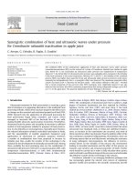
Torsional Vibration Method
Apart from the direct calculation, the torsional vibration, [13]–[16] is another usual
means of inertia measurement. The entire system is composed of a vertical rod or wire
securely clamped and rigidly supported from its upper end, and a collar clamped at the
lower end to connect the rod and the parts to be measured, i.e. the motor rotor.
- 12 -
Chapter II
Rod
t
t0
Rotor of
Collar
Calibration
Spindle Motor
Jc
Object
J0
J
Fig. 2.2 Torsional Vibration Illustration
First of all, a calibration part whose inertia value must be known accurately is installed
on the collar. After that, the system is set in torsional vibration with respect to the axis
of the rod and the natural frequency of this system is measured and denoted as t0.
Secondly, with the calibration part dissembled from the collar, the part for
measurement, i.e. motor rotor together with loads and other fixture parts, is installed
on the collar. Again, the new system is set in torsional vibration according to the same
rotational shaft as the previous one. The natural frequency now is also measured and
denoted as t. Given the collar inertia value, denoted as Jc, and calibration inertia value
as J0, the inertia value of the latter installed part, which is of our interest of
measurement, can be calculated from the following equation.
2
⎛t ⎞
J = ( J0 + Jc ) ⎜ ⎟ − Jc
⎝ t0 ⎠
(2.5)
- 13 -
Chapter II
Nevertheless, in HDD, if this method were carried out, the rotor together with the plate
and some fixtures had to be removed from the motor frame. As is stated above, the
inertia value obtained in this manner may differ from the actual value when the entire
system is assembled because of the inevitable assembly error. Moreover, it is very
troublesome in mass production if the rotor and the disk have to be disassembled for
measurement and reassemble after measurement. The whole process is very time
consuming.
Pendulum Method
Alternatively, the pendulum, which also involves oscillation, is another way similar to
the torsional vibration method commonly utilized for inertia measurement. As is
shown in [13], usually, the rotational shaft of the motor is set to be horizontal with a
vertical rod connected perpendicularly to the shaft. Next, the weight is lifted to some
height and released to swing for pendulum movement. The period of oscillation is
measured and the inertia of the weight about the horizontal rotational shaft is also
calculated. The following figure demonstrates the basic setup of this method.
- 14 -