Optical limitng and field emission studies of carbon nanotubes
Bạn đang xem bản rút gọn của tài liệu. Xem và tải ngay bản đầy đủ của tài liệu tại đây (2.21 MB, 83 trang )
OPTICAL LIMITING AND FIELD EMISSION STUDIES
OF CARBON NANOTUBES
GOHEL AMARSINH
NATIONAL UNIVERSITY OF SINGAPORE
2004
OPTICAL LIMITING AND FIELD EMISSION STUDIES
OF CARBON NANOTUBES
GOHEL AMARSINH
B.Sc. (Hons.)
SUPERVISOR
A/PROF ANDREW WEE
THESIS SUBMITTED
FOR THE DEGREE OF MASTER OF SCIENCE
DEPARTMENT OF PHYSICS
NATIONAL UNIVERSITY OF SINGAPORE
2004
Table of Contents
Abstract
Chapter 1
1.1
1.2
1.3
1.4
1.5
1.6
1.7
1.8
1.9
1.10
1.11
References
Chapter 2
2.1
2.2
i
Introduction
Carbon
Properties of Carbon
Carbon Nanotubes
Structure of Carbon Nanotubes
Electronic Structure of Carbon Nanotubes
Synthesis Methods of Carbon Nanotubes
1.6.1 Arc Discharge
1.6.2 Laser Ablation
1.6.3 Catalytic Growth
Growth Mechanisms
Applications of Carbon Nanotubes
1.8.1 Nano-electronic Devices
1.8.2 Nanoscale Junctions
1.8.3 Nanoprobes
1.8.4 Nanoelectrodes
Optical Limiting Effects of Carbon Nanotubes
Carbon Nanotubes as Field Emitters
1.10.1 What is Field Emission
1.10.2 Why Carbon Nanotubes
Aim of Project
1
1
2
3
4
6
7
7
8
10
10
12
12
13
13
14
14
17
17
19
20
21
Experimental Techniques
Synthesis Techniques
2.1.1 Sputter Deposition of Catalyst
2.1.2 Chemical Vapour Deposition
2.1.3 Electron Beam Evaporator
Characterization and Measurement Techniques
2.2.1 Scanning Electron Microscope
2.2.2 Transmission Electron Microscopy
2.2.3 Raman Spectroscopy
2.2.4 Synchrotron Light Source
2.2.5 Photoelectron Spectroscopy
2.2.6 X-ray Photoelectron Spectroscopy
2.2.7 Optical Limiting Measurements
2.2.8 Field Emission Measurements
23
23
23
25
27
28
28
39
30
31
32
33
34
36
38
References
Chapter 3
3.1
3.2
3.3
Optical Limiting Properties of a-Au and a-Ag Coated
Carbon Nanotubes
Introduction
Surface Plasmon Absorption in Au and Ag Nanoparticles
Experimental Procedure
3.3.1 Synthesis of Random Carbon Nanotubes
39
39
39
41
41
3.4
3.5
References
Chapter 4
4.1
4.2
4.3
4.4
References
Chapter 5
3.3.2 Why Random MWNTs
3.3.3 Coating of a-Au and a-Ag Nanoparticle Film
3.3.4 Optical Limiting Measurements
Results and Discussion
Conclusion
43
44
46
48
54
55
Field Emission Properties of Plasma Etched MWNTs
Introduction
Experimental Details
4.2.1 Experimental Procedures
4.2.2 Field Emission Set-up
Experimental Results
4.3.1 N2 Treated MWNTs
4.3.2 Ar Treated MWNTs
Conclusion
56
56
56
56
57
58
65
72
72
74
Conclusion
75
Acknowledgements
77
Abstract
In this research, we investigate two of carbon nanotubes’ most well known
properties: optical limiting and field emission. Our aim is to modify the carbon nanotubes
using physical and chemical means to modify their optical limiting and field emission
characteristics.
In the first part of this thesis, we coat randomly aligned multi-walled carbon
nanotubes (MWNTs) with a-Au and a-Ag nanoparticles. The optical limiting
characteristics of as-grown MWNTs and the coated MWNTs are then measured and
compared at 532nm and 1064nm using a nanosecond laser. It is observed that, at 532nm,
the coated MWNTs show better optical limiting characteristics compared with the
original MWNTs while there is no observable enhancement at 1064nm. We propose
surface plasmon absorption of the a-Au and a-Ag nanoparticles on the coated MWNTs to
be the mechanism responsible for the improvement in optical limiting. UV spectrum of
the samples and non-linear scattering measurements further confirmed the validity of this
mechanism.
In the second part of the thesis, we modify the MWNTs by plasma etching with
N2 and Ar for 10min and 20min each. The field emission characteristics of the etched
samples are then measured using a custom-made chamber and compared to that of
MWNTs. The N2 etched MWNTs showed great improvement in field emission
properties, while the Ar etched MWNTs displayed poorer field emission characteristics
compared to the parent MWNTs. Various methods of characterization, such as XPS, PES,
SEM and Raman spectroscopy are used to investigate these observations and an
explanation to our results is proposed.
Chapter 1
Chapter 1: Introduction
In this chapter, an introduction to carbon nanotubes is provided. Although their
properties and synthesis methods are widely studied and well known, carbon nanotubes
are central to this project, thus an extensive treatment is provided.
1.1
Carbon
Carbon is the sixth element in the periodic table and the lightest of the Group IV
elements. Owing to carbon’s unique electronic configuration: (1s2, 2s2, 2p2), it has many
distinct properties that set it apart from other Group IV elements such as silicon and
germanium. This is mainly due to the fact that carbon is able to undergo sp1, sp2 and sp3
hybridisation (other Group IV elements only form sp3 bonding). This allows carbon to
readily bond with many other elements to form a variety of compounds, and also allows
carbon to exist in many different forms of allotropes, such as graphite and diamond.
Carbon has interested researchers since the 19th century when Thomas A. Edison
used a carbon fiber as the filament for the first electric bulb (1). Although the much more
effective tungsten filament soon replaced the carbon fiber filament, development of the
carbon fiber proceeded rapidly through the efforts of researchers round the world. A
major stimulus for carbon research started in the 1950s when the space and airline
industry brought about an increased demand for strong, stiff and lightweight fibers (1).
This served as a catalyst for developments in carbon fiber preparation techniques based
on polymer precursors. The carbon whisker was also synthesized during this period,
which became the benchmark for carbon fiber properties. Through continual efforts by
researchers and improvements in technologies, synthesis methods were being perfected
1
Chapter 1
as defects of synthesized fibers were reduced and properties enhanced. With the
invention of the catalytic vapour deposition process, researchers now had greater control
of the fabrication process.
As the dimensions of the carbon fibers continue to decrease, questions are being
asked as to if there exists a lower limit. Then came the discovery of fullerenes by Kroto
and Smalley, which paved the way for nanoscale carbon fibers (2). As fullerene synthesis
techniques were being improved upon, there was much speculation of the existence of
carbon fibers with the dimensions comparable to that of fullerenes. The breakthrough
came with S. Ijima’s discovery in 1991, when he observed the first nanoscale carbon
nanotube using transmission electron microscopy (3).
1.2
Properties of Carbon
The uniqueness of carbon stems from the fact that it is able to undergo various
forms of hybridisation that allows it to form various allotropes. In ambient conditions, the
stable graphite phase is formed, with carbon atoms in a planar sp2 bonding arrangement.
Under high pressure and temperature, carbon switches to tetrahedral sp3 bonding forming
diamond, which continues to remain largely stable after the release of pressure.
Properties of carbon vary differently when in the graphite state and in the
diamond state. Graphite exhibits metallic behaviour in the intra-plane direction but poor
electrical conductivity in the inter-plane axis (4). Graphite is also the stiffest material
known, having the highest in-plane elastic modulus. On the other hand, diamond shows
wide-gap semiconductor behaviour, and is the hardest known material (5). Diamond also
has the highest atomic density of any known solid.
2
Chapter 1
Of all the fullerenes, icosahedral C60 is the most stable and common (6). Within
the shell, the carbon atoms mostly form sp2 bonding, although some sp3 bonding is
present as well to accommodate the curvature of the shells. The second most common
fullerene is C70, which is formed from C60 by adding five hexagons around the equator of
the C60 shell, and rotating the two halves of the C60 shell by 360 with respect to each other
to form the rugby-shaped fullerene. It is interesting to note that the average carboncarbon bond distance is approximately 1% larger than that of graphite; hence one would
expect the properties of fullerenes to mirror closely with graphite.
1.3
Carbon Nanotubes
Carbon nanotubes are essentially one-dimensional tubular fullerenes, with
nanometer diameters and properties similar to that of graphite fibers. They can be
visualized to be formed by rolling up a graphene sheet into a cylinder. Carbon nanotubes
have shown remarkable properties that made it one of the most exciting materials in the
past decade (3). They have a high aspect ratio, incredible mechanical strength and
excellent electrical properties, giving them the possibility of being employed in various
diverse applications such as hydrogen storage, scanning tunnelling microscopy tips and
field emission displays.
The uniqueness of the carbon nanotube structure is attributed to the helicity in the
arrangement of carbon hexagons on the surface layer honeycomb lattice. The helicity,
which is determined by symmetry and tube diameter, introduces modifications to the
electronic density of states, hence giving the nanotubes a unique electronic character (3).
Meanwhile, the topology of the carbon nanotubes has important effects on their physical
3
Chapter 1
properties. In fact, there have been theoretical reports suggesting the existence of strong
structure-property correlation, bringing new excitement to the study of this material (7).
1.4
Structure of Carbon Nanotubes
There are essentially two broad categories of carbon nanotubes: single-walled and
multi-walled. Single-walled carbon nanotubes (SWNT) were first reported in 1993, and
are essentially singular graphene cylindrical walls with diameters that range between
1~2nm (8). Multi-walled carbon nanotubes (MWNT), first observed by Ijima in 1991,
consist of several nested cylinders that have an interlayer spacing of 0.34nm, much like
the interlayer distance of bulk graphite. There is no three-dimensional ordering between
the individual graphite layers, unlike that of graphite, suggesting that the interlayer
structure is turbostratic. The outer wall diameters can be as large as 50nm while the inner
hollow has a diameter of up to 8nm.
There are several ways in which a graphene sheet can be rolled up to a cylinder to
form a single-walled nanotube (9). The boundary conditions around the cylinder are
satisfied only when one of the Bravais lattice vectors in the plane of the graphene sheet
maps to the complete circumference of the cylinder. The Bravais lattice vectors are
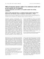
formed by the linear combination of two primitive lattice vectors (Fig. 1.1) (10),
R = ma1 + na2
(1)
Hence, the structure of a SWNT can be described by the integer pair (m, n).
Different SWNT structural configurations can be produced. A zig-zag tube, (n, 0), or
armchair tube, (n, n), is obtained when the sheet is rolled up along one of the symmetry
axis (8). The graphene sheet can also be rolled up in a direction away from the symmetry
4
Chapter 1
semiconductor
metal
Fig 1.1: Possible vectors defined by the integer pair (m, n) for different classes of
nanotubes (Adopted from (10)).
axis. This forms a chiral nanotube (m, n), in which the atoms in a unit cell are aligned in a
spiral. Besides differing in terms of chiral angle, nanotubes also differ in diameter.
Hence, a nanotube is commonly characterized by its diameter d and chiral angle , which
are defined as follows:
d
a n2
m2
nm
12
ar cos 3 n m / 2 n 2
(2)
m2
nm
1 2
(3)
Such a diversity of structural configurations is commonly found in practice, and there is
no particular preference as to which type of nanotube is formed (8). In most
circumstances, the walls of MWNTs are chiral (3) and have different helicities (11). Both
SWNTs and MWNTs have high aspect ratios, with ~µm lengths and diameter ranging
from ~1nm for SWNTs to ~50nm for MWNTs.
5
Chapter 1
If SWNTs were formed by rolling up a graphene sheet, then they would be openended. However, pristine SWNTs are mostly observed to be capped at both ends by
fullerene half-spheres that contain both pentagons and hexagons (9). TEM images of a
SWNT show a well-defined spherical tip while that of a MWNT show a more polyhedral
cap. Sometimes, open-ended nanotubes can be observed. Such situations occur when the
cap of the nanotube is removed and the ends of the graphene layers and internal cavity of
the tube is exposed.
Defects can also be present in the hexagonal lattice body of the carbon nanotube
in the form of pentagons and heptagons. Pentagon defects are mostly found at the cap and
produce a positive curvature of the graphene layer. Negative curvatures of the tube walls
are due to the presence of heptagonal defects (12). Sometimes, these defects can be
formed by several pentagons or heptagons forming together, or even in combination.
These defects alter the shape and dimensions of the nanotubes without causing any strain
in the structure through lattice distortions. The end result is the alteration of helicity of
the nanotubes by the insertion of junctions, which allow nanotubes of different electronic
structure to be linked (13).
1.5
Electronic Structure of Carbon Nanotubes
Much has been studied about the electronic structure of SWNTs. Research has
shown that the electronic properties vary in a predictable way from metallic to
semiconducting with structural variations, which is due to the unique band structure of
graphene (14). Graphene is a zero-gap semiconductor as the energy bands of its pelectrons cross the Fermi level at the Brillouin zone edges (8). Although it should behave
6
Chapter 1
like a metal at room temperature, in reality it shows a semi-metallic behaviour because
the electron density at the Fermi level is quite low (15). When the graphene sheet is
rolled up to form a cylinder, periodic boundary conditions are imposed at the
circumference, which limits the number of electron wave vectors perpendicular to the
tube axis. When these wave vectors cross the edge of the Brillouin zone, the carbon
nanotube is metallic in nature. All armchair tubes and one third of zig-zag and chiral
tubes are metallic. For the rest of the nanotubes, they all show a gap in their band
structure, thereby exhibiting semiconductor behaviour, with a band gap that scales
inversely with the tube radius. For zig-zag and chiral metallic nanotubes, there is actually
a small band gap due to hybridisation effects caused by tube curvature in very small
tubes. This is not observed in armchair nanotubes as they are strongly metallic.
The experimental evidence for these theoretical predictions came only in 1998
with scanning tunnelling spectroscopy (16, 17). Conductivity measurements have shown
that SWNTs act as coherent quantum wires where the conduction takes place via discrete
electron states. Transport measurements show that the coherence lengths in SWNTs are
extremely long (18). MWNTs also show similar effects although they have multiple
shells and larger diameters.
1.6
Synthesis Methods of Carbon Nanotubes
1.6.1
Arc Discharge
The arc discharge was the first method used for the production of SWNTs and
MWNTs (3). In fact, it was at the ends of graphite electrodes used in an electric arc
discharge where Ijima first observed carbon nanotubes. Since this method has been used
7
Chapter 1
for the synthesis of carbon fibers, it is possible that nanotubes were already observed
before 1991 but were not identified (19). An arc is struck between two graphite
electrodes in He gas atmosphere at typical conditions of 16V bias and currents of up to
80A at 400mbar pressure. MWNTs produced using this method are long, straight tubes
that are closed at both ends. By using an arc discharge with a cathode containing Ni or Fe
catalysts and graphite powder mixture, SWNTs can be synthesized. The yield of the
SWNTs has been increased over the years by optimising the catalyst mixture and
deposition conditions (20).
1.6.2
Laser Ablation
Laser ablation was first demonstrated to synthesize SWNTs in 1996 (21). The
synthesis is carried out in a horizontal flow tube in the presence of an inert gas flow. The
laser is used to vapourize the transition metal graphite composite electrode target at
temperatures up to 12000C. Two laser pulses are used in the process: the first is to ablate
the carbon-metal mixture while the second breaks up the larger ablated particles in order
for them to take part in the nanotube growth process. SWNTs condense from the
vapourization plume and are collected outside the furnace. The yield of this technique has
been improved by using rotating targets and continuous ablation and is able to produce up
to gram quantities. By varying the temperature of the process, the diameter of the
synthesized nanotubes can be controlled.
8
Chapter 1
(a)
anode
plasma
deposits
cathode
pumps
DC
Source
(b)
Oven 1100oC
target
collector
Laser pulse
Oven 1100oC
N2
(c)
Oven 720oC
sample
Quartz plate
Oven 720oC
C2H2
N2
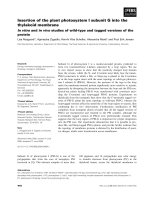
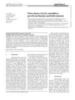
Fig. 1.2: Schematics of the different carbon nanotube growth methods and the TEM
images of the carbon nanotubes grown by the respective methods. (a) arc discharge, (b)
laser ablation, (c) catalytic deposition.
9
Chapter 1
1.6.3
Catalytic Growth
The catalytic growth method essentially involves the decomposition of
hydrocarbon gas in the presence of a transition metal catalyst in a chemical vapour
deposition chamber. In 1993, this approach was used to grow MWNTs by the
decomposition of acetylene over Fe particles at temperatures of about 6000C-8000C (22).
A much higher temperature of ~11000C is required for the synthesis of SWNTs as they
have a higher energy of formation. Due to the high temperature, carbon monoxide or
methane is used as the carbon source as they are more stable than acetylene. The catalytic
growth method is ideal for the growth of nanotube film on planar substrates such as
silicon.
The catalytic growth method has garnered much attention because of several
advantages that the method has over other synthesis processes (8). Firstly, the process
produces very few or no codepositied carbon allotropes, thus eliminating the need for
further purification process. Secondly, since catalytic growth method allows the synthesis
of nanotubes directly on substrates, lithographic methods can be used to pattern the
catalyst on these planar substrates, thereby allowing for patterned or selective area
growth. By controlling the size of the pores of the catalyst, one is also able to control the
diameter of the synthesized carbon nanotubes.
1.7
Growth Mechanisms
Studies of catalyst grown multiwalled carbon nanotubes indicate that growth
occurs through precipitation of dissolved carbon from a moving catalytic particle surface
(23). Growth terminates when the catalyst particle is deactivated or when stable metal
10
Chapter 1
carbide is formed. It is energetically favourable for the surface of the newly formed fibre
to precipitate as low energy basal planes of graphite; hence the nanotubes form in tubular
morphology. However, due to the curvature of the graphite layers, an additional elastic
energy term is introduced into the free energy equation of nucleation and growth. As a
result, a lower limit to the diameter of the carbon fibres that can from curved graphite
layers is installed. The implication of this is that in order for us to explain the growth of
carbon nanotubes, new mechanisms must be thought of.
The growth of MWNTs and SWNTs might occur via two different mechanisms.
Open MWNTs are seldom observed in samples grown via the arc method. During
nucleation, all the growing layers of the tube remain open during growth. A layer
undergoes closure because of pentagonal rings formed due to disturbances or
perturbations during the growth process or due to stability considerations between
structures with hexagonal and pentagonal morphology. Hence, open-ended tubes are
improbable since the dangling bonds at the ends would cause a large increase in the
energy of the system. This energy is minimized through interactions between adjacent
layers. Bonds present between layers are dynamic, and incorporation of carbon species
during growth occurs through continuous breaking and reforming of the lip around the
fringe of an open-ended tube.
A mechanism suggested for SWNT growth involves the role of a catalyst during
growth. Catalyst atoms decorate the dangling bonds of the open end of a tube and achieve
growth by a ‘scooter’ mechanism. The catalyst atoms ‘scoots’ around the rim of the open
tube and absorb incoming carbon atoms, causing the tube to grow. However, through
theoretical calculations, it is shown that SWNTs will have a strong tendency to form
11
Chapter 1
close ends by forming pentagons and ejecting any catalyst atoms. Until now, however,
there is no consensus as to which is the dominant mechanism that governs the growth of
SWNTs (24).
1.8
Applications of Carbon Nanotubes
Since their discovery, researchers around the world have tried to utilise the unique
electronic structure, mechanical strength, flexibility and dimensions of carbon nanotubes
for a wide range of applications. Most of these applications apply to both SWNTs and
MWNTs, although electronic applications based on SWNTs show more success.
1.8.1
Nano-electronic Devices
Carbon nanotubes are viewed as ideal 1-D nanostructures, hence they show great
promise as quantum wires and in tiny electronic devices. The Delft group built the first
single molecule field-effect transistor, using individual semiconducting SWNTs (25). The
transistor is made of a nanotube connecting two metal electrodes and operates at room
temperature. The band structure for this device is similar to that of two Schottky-type
diodes connected back to back and its performance is comparable in switching speeds to
existing devices. The next crucial step in this application would be to integrate the device
into circuits. However, existing technology in nanotube fabrication does not allow the
construction of the complex device architecture that the industry needs today. The only
solution is to have self-assembly of the carbon nanotubes in the desired architecture. This
has to be realized first before nanotubes electronics can become a practical reality.
12
Chapter 1
1.8.2
Nanoscale Junctions
There is the possibility of joining nanotubes of different helicity, which would
lead to the fabrication of heterojunction devices (26). MWNTs have been studied and
there are observations of varying changes in electronic properties along the length of the
tubes. Junction devices can be designed from two nanotube segments, one of which is
semiconducting and another that is metallic in nature through doping with impurities such
as boron. As such, a whole new branch of nanoscale physics is beginning to develop.
Predictions and theoretical models have already paved the way for this field to advance.
1.8.3
Nanoprobes
A novel use of nanotubes is as nanoprobes for such as tips of a scanning probe
microscope (27). This application makes use of the nanotubes’ high aspect ratio,
mechanical strength and elasticity. A successful demonstration is the use of a nanotube
tip on an atomic force microscope that was used to image the topography of TiN-coated
aluminium film. A bundle of MWNTs is first attached to the cantilever using adhesive
bonding. The free end of the bundle is then sheared to form the ‘sharp’ tip. Owing to its
flexibility, nanotube tips do not crash as readily as the conventional tips. Also, the
dimension of the nanotube tip makes it particularly suitable to image deep features like
cracks. As nanotubes are conducting, they can be used as tips for the scanning tunnelling
microscope. This seems a really promising application of carbon nanotubes; however, the
vibration of individual freestanding tips can disrupt some of the advantages brought by
the small tube dimensions, especially during high-resolution imaging.
13
Chapter 1
1.8.4
Nanotube Electrodes
The potential of nanotubes playing the roles of electrodes is also being hotly
researched, particularly due to the fact that carbon based electrodes have been used for
decades in important electrode applications such as fuel cells and batteries. Initial studies
using MWNT electrodes in bioelectrochemical reactions showed high reversibility and
catalytic activity at the nanotube electrodes (25). Nanotubes can catalyse oxygen
reduction reactions, where the electron transfer rates are much higher than those observed
on other carbon-based electrodes. As oxygen is an important reaction in fuel cells, this
clearly shows the potential of nanotubes serving as electrodes in such devices.
1.8
Optical Limiting Effects of Carbon Nanotubes
Carbon nanotubes also show excellent optical limiting characteristics. This was
first reported with experimental evidence by P. Chen et al in 1999 (28). This discovery
opened a whole new field of applications for carbon nanotubes. This property can be
applied to photonic devices, such as optical switches and optical communications.
However, much of the research done up till then on the electronic and optical properties
of carbon nanotubes have been theoretical predictions instead of actual experimental
measurements. Here I shall discuss the optical limiting property of carbon nanotubes
based on the work done in that landmark paper.
The carbon nanotubes are dissolved in a suitable solvent such as ethanol. Laser
pulses of wavelengths 532nm and 1064nm are used. It is observed that at incident
fluences lower than 0.06 J/cm, energy transmittance is a constant. At higher fluence
energies, energy transmittance decreases with increasing incident fluence, exhibiting
14
Chapter 1
optical limiting property. The experiment is repeated for 1064nm wavelength laser pulses
and a similar trend is observed. This confirms carbon nanotubes as possessing broadband
optical limiting qualities (28).
The same experiment is also repeated for C60 and carbon black, where the
concentration is normalized for easy comparison. The limiting threshold, which is
defined as the incident fluence at which transmittance falls to that of linear transmittance,
is around 1.0 J/cm2 for carbon nanotubes, lower than C60 and carbon black at 532nm. At
1064nm, limiting phenomenon totally vanishes for C60, while carbon black has a much
higher limiting threshold.
In C60, the dominant mechanism to explain the optical limiting property is excited
state absorption. Ground-state absorption promotes electrons into excited states. There is
no ground-state absorption at 1064nm, hence there is no optical limiting observed in that
wavelength.
For carbon nanotubes, ground-state absorption is absent in both 532nm and
1064nm. From the electronic structure study of carbon nanotubes, carbon nanotubes have
a lower work function, lower binding energy and stronger plasma excitation. This,
coupled with the fact that carbon nanotubes show broadband limiting response, suggests
that the limiting property results from a different mechanism, nonlinear scattering.
Coincidentally, this mechanism is determined to be the dominant process for carbon
black suspensions.
15
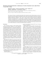
Chapter 1
Scattered light
Incident
Laser pulse
Detector
Transmitted
pulse
Expanding
microplasmas
Fig 1.3: Schematic of Non-linear Scattering Process
During nonlinear scattering, heating of the carbon nanotubes by the laser pulses
lead to vaporisation and ionisation of carbon particles, and then the formation of rapidly
expanding microplasmas. These microplasmas strongly scatter light in the transmitted
beam direction, thereby leading to a decrease in the transmitted light direction. At the
same time, the nanotubes conduct heat to the surrounding liquid, leading to the
generation of solvent microbubble growth, which also plays a part in decreasing the
measured transmitted light.
16
Chapter 1
1.9
Carbon Nanotubes as Field Emitters
With conventional cathode ray tubes gradually being replaced by flat panel
displays, there is a great interest in electron field emitters. This can be credited to the
recent development of cheap and robust field emitting materials. One such material is the
carbon nanotube.
1.9.1
What is Field Emission?
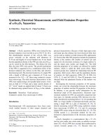
Field emission is the process whereby electrons are emitted under high field
conditions from the surface of a solid by tunnelling through the surface potential barrier
(29). As shown in Fig1.4, The potential barrier is square-shaped when no electric field is
applied. When a potential is applied, the surface potential barrier becomes triangular. The
amplitude of local field F just above the surface of the solid determines the gradient of
the slope. The local field F is given by
F
V
d0
(4)
where V is the applied voltage, d0 the distance between the two parallel electrodes, and ß
is the field enhancement factor. Field emission peaks at the Fermi level; hence, field
emission is determined by the workfunction . The Fowler-Nordheim model describes
the dependence the emitted current on the local field and workfunction as
I
F2
exp
B
3 2
F
(5)
where B = 6.83 X 10⁹ (V eV-3/2 m-1). From the relationship, we can see that the emitted
current is strongly affected by factors such as variations in the shape of emitter and the
chemical state of the solid or its surface. When the field emission follows the Fowler-
17
Chapter 1
Nordheim model, one can determine either
or ß from the slope of the Fowler-Nordheim
plot, which is determined by plotting ln I V 2 against 1 V .
metal
surface
vacuum
F=0V/nm
EF
D(EF)
D(E)
F=2V/nm
Fig. 1.4: Field emission model from a metal emitter (29).
Field emitters are preferred over thermoelectric emitters because of several
advantages (29). Firstly, field emitters do not need be heated, hence there is no need for
the installation of a heater in the device. Secondly, the electrons emitted by field emitters
have a smaller energy spread. Thirdly, field emitters are easily synthesized in
microscopic or nanoscale dimensions and can be made into arrays. Lastly, the emitter
current is easily controlled by applied voltage.
18
Chapter 1
1.9.2
Why Carbon Nanotubes?
Carbon nanotubes are viewed as one of the most exciting materials for a field
emitter cathode, one of the key discoveries that will spearhead field emission displays to
the top of the flat panel display market. There are several reasons for this:
High aspect ratio
High mechanical strength
Conductive
Low turn-on fields
High current densities
Easy to fabricate
19
Chapter 1
1.10 Aim of Project
As discussed in the sections before, owing to their wide range of excellent
properties, carbon nanotubes are being earmarked for a variety of applications, two of
which are as optical limiting materials and field emission cathodes. In this project, we
attempt to modify MWNTs in a bid to enhance their original properties.
The first part of the project attempts to enhance MWNTs as optical limiters by
coating a layer of a-Ag or a-Au. Au and Ag nanoparticles are known to possess large
nonlinear optical properties and ultrafast time response and their optical properties were
also actively studied by picosecond and femtosecond laser in the surface plasmon
absorption region. Hence, we attempt to combine MWNTs with Au and Ag to form new
composite materials with optical limiting properties that exceed that of pure nanotubes.
The second part of the project investigates carbon nanotubes as field emitters.
There has been much research on improving the field emission properties of carbon
nanotubes, such as chemical doping and structural modifications. Here, we modify the
carbon nanotubes via Ar and N2 plasma etching, before measuring their respective field
emission characteristics. We characterize the modified MWNTs in comparison to the
parent MWNTs using various techniques such as SEM, UPS, XPS and Raman
spectroscopy.
20