Diamond like carbon (DLC)
Bạn đang xem bản rút gọn của tài liệu. Xem và tải ngay bản đầy đủ của tài liệu tại đây (503.05 KB, 30 trang )
Diamond like carbon (DLC)
Diamond vs DLC
Hybridisation of Carbon
DLC
•
•
•
Carbon exist in SP3 , SP2 , SP hybridised states
•
•
DLC has network of graphitic clusters linked into islands by SP3 bonds.
•
structurally they are amorphous in nature with sp2 and sp3 bonded carbon
atoms
SP3 – Diamond, SP2 - Graphite
DLC is a metastable form of amorphous carbon, with or without hydrogen, which
contains a significant fraction of sp3 bonded carbon atoms.
DLC has similar properties of diamond, but these are achieved by the isotropic
thin films with no grain boundaries.
Carbon-Hydrogen alloys
ta-C – Tetrahedral amorphous carbon
ta-C:H – Hydrogenated ta -C
a-C:H – amorphous hydrogenated -C
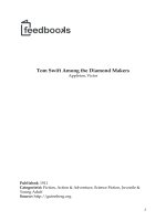
Ternary phase diagram of bonding in amorphous carbon-hydrogen alloys
DLC
2
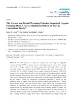
Schematic of SP clusters in a-C:H
3
2
2
Mixture of SP and SP sites. DLC has always SP sites
ta-C with > 70% of SP
3
Properties depend on the composition of films
DLC - properties
•
•
•
•
•
•
The structure and properties of DLC films are largely dependent on the
hydrogen content and the ratio of sp2 to sp3 bonded carbon atoms
Hydrogen content reduces hardness and density
Hydrogen content increases the band gap and the electrical resistivity
Hydrogen content also affect the optical properties and decreases the refractive
index
Dopants ( B, N, O, F, Si, Ti, W, Nb) manipulate the properties of DLC films
DLC has high mechanical hardness, very low surface roughness, chemical, optical
transparency, electrochemical inertness and a wide band gap semiconductor.
DLC-Properties
•
•
•
•
•
Unlike Diamond, DLC can be p and n doped
•
Electronic properties depend on number of SP2 sites, this controls the band gap.
All DLC have π bonds.
•
Optical band gap decreases with increase in SP2 fraction
At high N content, band gap reduces and new SP2 sites increases.
DLC has low surface energy
Density dependent on number of SP3 sites
Mechanical properties depend on the local C-C coordination. SP3 increases youngs
modulus increases.
Comparison of different C forms
DLC
Preparation of DLC
•
DLC films may contain significant amounts of hydrogen depending on the source
of carbon and deposition process.
•
Hydrogen-free DLC coatings are prepared by solid carbon or graphite targets
with arc physical vapor deposition, pulsed laser deposition, and magnetron
sputtering techniques
Preparation of DLC
•
•
•
DLC are easy to prepare compared to diamond
•
More SP3 with less hydrogented films were deposited by PECVD. Hydrogenated
tetrahedral carbon – (ta-C:H)
DLC contains amorphous (a-C), hydrogenated alloys (a-C:H)
Deposition methods like Plasma enhanced chemical vapour deposition (PECVD),
sputtering are used to prepare a-C with with higher SP3 content
General deposition methods
•
Chemical vapour deposition (CVD) – High temperature, specific choice of
substrates, polycrystalline film, more hydrogen content and more grain
boundaries.
•
Physical vapour deposition (PVD) – Sputtering, ion beam, mass selected ion
beam (MSIB) plasma, Pulse laser, cathodic vacuum arc
DLC deposition methods
•
•
•
•
•
Ion beam
PECVD
Sputtering
Cathodic vaccum arc
Pulse laser deposition
Deposition techniques
Deposition mechanism
•
Diamond like carbon deposition takes place with optimum ion ( carbon or hydrocarbon ions) energy
bombardment ~ 100 eV
•
SP3 fraction and H contents of DLC films depends mainly on ion energy
Ion beam deposition
Carbon or hydrocarbon ions are generated by plasma sputtering of graphite
cathode or gas (methane) ionization in a plasma.
Ions are extracted and accelerated using power grids
Ion beam were directed into deposition vacuum chamber
Deposition on the substrate
Mass selected Ion beam (MSIB)
•
•
•
•
Controlled deposition from single ion species with well-defined ion energy
Accelerated ions passed are through the magnetic filters
+
It filter out neutral species and selects the C
Ions can be decelerated to desired ion energy using electrostatic lens and
deposited on the substrate
Sputtering
Most common method for depostion of DLC
Ar Plasma generation
Magnetron sputtering is used to increase the yield (magnets are placed behind the
target causes the Electron to achieve higher path length and thereby It increases
the plasma ionisation).
DC bias is applied to the substrate to vary the ion energy
a-C:H produced by Reactive sputtering ( Ar, and H or CH4)
a-CNx can be produced by using ( Ar + N plasma)
Disadvantage – Less ratio of Ions to neutral species (less hard)
Ion assisted sputtering
A beam of Ar ion is used to sputter the graphite traget
Additional Ar beam can be used to bombard the growing film
3
to densify the film or encourage SP bonding
Cathodic vacuum arc
Touching graphite cathode with carbon striker
electrode and withdrawing initiate the arc. (In vacuum)
High ion density (10
13
3
cm )plasma is generated
by above process
Low voltage, high current density power supply
(cathode spot is very small [1-10 µm])
Particulate and plasma can be filtered by using magnetic filter ducts. (Filtered
Cathodic Vacuum Arc) (Shown in the next slide)
FCVA are used to prepare highly ionised plasma with an energetic species low ion
energy distribution and high growth rate (1 nm/s)
Unlike ion beam deposition, the depositing beam in FCVA is neutral plasma beam,
which can be deposited on the insulating substrates.
Filtered Cathodic vacuum arc (FCVA)
•
Particulates cannot follow the field. they hit the walls of the filters. ( S bends gives improved filtration)
•
Neutral species also hit the walls, so the filters raises the ionisation of plasma from 30% to 100 %.
•
Finally plasma beam are condensed on the substrate to produce ta-C
Single bend
S bend
Plasma deposition
Plasma decomposition of hydrocarbons ( acetylene)
Two electrodes with different area
Higher mobility of electrons than ions create a
sheath next to electrode with excess of ions
For DLC deposition the plasma has to operated at
lowest possible pressure
This will increase the fraction of ions to radical
of the plasma
In pressure plasma, use of magnetic field, increase
the path length of electron and the ionisation efficiency
Pulsed laser deposition
A very short pulse of intense laser vaporise materials as intense plasma
The expanding ions in plasma strikes the substrate and deposit as film
This is used to coat many different materials
Characterisation methods
•
•
•
•
•
•
•
•
Raman spectroscopy
IR Spectroscopy
Nuclear magnetic resonance ( C13 NMR)
Electron energy loss spectroscopy
Electron spectroscopy for chemical analysis (ESCA)
UV spectroscopy
Ellipsometry
X Ray reflectivity, Neutron diffraction
Applications
•
Optical windows - a-C:H forms transparent thin films. (UV, Visible)
•
Magnetic storage disks – higher capacity and less wear of disk materials. No
pinholes even with 1.2 nm thick film
•
Antifuses - as the high current passes it affords less resistance. DLC acts as
semiconductor, hence increase in temperature increases the conductivity.
Nitrogen doped DLC are better antifuses
•
Low dielectrics films – Device dimension decreases with DLC films. Lower
dielectric constant than SiO2