Tài liệu biến tần I68E EN 02+v1000+datasheet
Bạn đang xem bản rút gọn của tài liệu. Xem và tải ngay bản đầy đủ của tài liệu tại đây (1.9 MB, 18 trang )
VZ
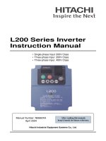
V1000
More performance & Quality in less space
•
•
•
•
•
•
•
•
•
•
•
•
•
Current vector control
High starting torque (200% / 0.5 Hz)
1:100 speed control range
Double rating ND 120%/1min and HD 150%/1 min
IM&PM motor control
Online Tuning
Low-noise Low carrier technology
10 years lifetime design
Built-in filter
Screw-less terminals
Control Terminals with memory backup
24 VDC control board power supply option
Fieldbus communications: Modbus, Profibus, CanOpen,
DeviceNet, Lonworks, CompoNet, Ethernet, ML-II
• Safety embedded: EN954-1 safety cat. 3, EN6158 SIL II and
EN60204-1 Stop category 0
• CE, UL, cUL and TUV
Ratings
• 200 V Class single-phase 0.1 to 4 kW
• 200 V Class three-phase 0.1 to 15 kW
• 400 V Class three-phase 0.2 to 15 kW
System configuration
Power
Supply
RS232 Communications cable with PC
MCCB
CX-Drive
CX-One
B
Co
US
py
Un
ER
it
R
Re
ad
Ve
rify
Co
py
M
CO
AC Reactor
CK
LO
-18
1
RJ-45 / USB
Adapter
USB Cable
Remote Operator
Extansion Cable
LCD Remote
Operator
A
KAW
YAS
OP
JV
Filter
24Vdc Control Board Power Supply
V1000
Communication Option Board
Mounting Accesories
Choke
Motor
Braking Resistor
DC Reactor
Ground
V1000
1
Specifications
Type designation
VZAB0P1BAA
Version
V1000 series
Coating specs:
A: Standard
Z:
Enclosure, Fin, Filter:
B: IP20 without top cover
F: Nema 1
E: IP20 without top cover and C3 filter
European standard
specifications
A: Standard specs
[”P” indicates a decimal point]
Max. applicable motor output
0P1: 0.1 kW
~
Voltage:
B: Single-phase 200 VAC
2: Three-phase 200 VAC
4: Three-phase 400 VAC
015: 15 kW
200 V class
B0P1
B0P2
B0P4
B0P7
B1P5
B2P2
B4P01
-
-
-
-
Three-phase: VZA@
For HD setting
For ND setting
Inverter capacity kVA
20P1
0.12
0.18
0.3
20P2
0.25
0.37
0.6
20P4
0.4
0.55
1.1
20P7
1.1
1.1
1.9
21P5
1.5
2.2
3.0
22P2
2.2
3.0
4.2
24P0
4.0
5.51
6.7
25P5
5.5
7.5
9.5
27P5
7.5
11
13
2011
11
15
18
2015
15
18.5
23
Rated output current (A) at HD
0.8
1.6
3.0
5.0
8.0
11.0
17.5
25.0
33.0
47.0
60.0
Rated output current (A) at ND
1.2
1.9
3.5
6.0
9.6
12.0
19.6
30.0
40.0
56.0
69.0
1.
2.
44P0
4.0
5.5
7.2
45P5
5.5
7.5
9.2
47P5
7.5
11
14.8
4011
11
15
18
4015
15
18.5
24
Proportional to input voltage: 0..240 V
Max. output voltage
Max. output frequency
400 Hz
Rated input voltage
and frequency
Single-phase 200..240 V 50/60 Hz
3-phase 200..240 V 50/60 Hz
Allowable voltage
fluctuation
-15%..+10%
Allowable frequency
fluctuation
+5%
Power
supply
Output
characteristics
Motor
kW2
Single-phase: VZA@
Only HD settings is available for this model
Based on a standard 4-pole motor for maximum applicable motor output:
Heavy Duty (HD) mode with a 150% overload capacity
Normal Duty (ND) mode with a 120% overlaod capacity
400 V class
Power
supply
Output
characteristics
Motor
kW1
1.
2
Inverter capacity kVA
40P2
0.37
0.37
0.9
Rated output current (A) at HD
1.2
1.8
3.4
4.8
5.5
7.2
9.2
14.8
18.0
24
31
Rated output current (A) at ND
1.2
2.1
4.1
5.4
6.9
8.8
11.1
17.5
23
31
38
Three-phase: VZA@
For HD setting
For ND setting
40P4
0.55
0.75
1.4
40P7
1.10
1.5
2.6
41P5
1.5
2.2
3.7
42P2
2.2
3.0
4.2
43P0
3.0
4.0
5.5
Max. output voltage
0..480V (proportional to input voltage)
Max. output frequency
400 Hz
Rated input voltage
and frequency
3-phase 380..480 VAC, 50/60 Hz
Allowable voltage
fluctuation
-15%..+10%
Allowable frequency
fluctuation
+5%
Based on a standard 4-pole motor for maximum applicable motor output:
Heavy Duty (HD) mode with a 150% overload capacity
Normal Duty (ND) mode with a 120% overlaod capacity
Frequency inverters
Specifications
Commom specifications
Model number
VZA@
Control methods
Output frequency range
Control functions
Frequency tolerance
Resolution of frequency set value
Resolution of output frequency
Overload capability
Frequency set value
Braking torque
(short term peak torque)
V/f Characteristics
Functionality
Inputs signals
Output signals
Standard functions
Analogue inputs
Braking/acceleration times
Protection functions
Display
Sine wave PWM (V/f control, sensorless current vector control)
0.1..400 Hz
Digital set value: ±0.01% (-10..+50 ºC)
Analogue set value: ±0.1% (25 ±10 ºC)
Digital set value: 0.01 Hz (<100 Hz), 0.1 Hz (>100 Hz)
Analogue set value: 1/1000 of maximum frequency
0.01 Hz
Heavy duty use: 150% rated output current for one minute
Normal duty use: 120% rated output current for one minute
0..10 V (20 kΩ), 4..20 mA (250 Ω), 0..20 mA (250 Ω)
Pulse train input, frequency setting value (selectable)
Short-term average deceleration torque: 150% (up 1.5 kW), 100% (for 1.5 kW), 50% (for 2.2 kW), 20% (fof bigger size)
Continous regenerative torque: Aprox 20% (125% with optional braking resistor, 10%ED, 10 s, braking transistor built itn)
Possible to program any V/f pattern
Seven of the following input signals are selectable: Forward/reverse run (3-wire sequence), fault reset, external fault (NO/NC
contact input), multi-step speed operation, Jog command, accel/decel time select, external baseblock, speed search command, UP/DOWN command, accel/decel hold command, LOCAL/REMOTE selection, communication/control circuit terminal
selection, mergency stop fault, emergency stop alarm, self test
Following output signals are selectable (NO/NC contact output, 2 photo-coupler outputs): Fault, running, zero speed, speed
agree, frequency detection (output frequency <= or => set value), during overtorque detection, minor error, during baseblock,
operation mode, inverter run ready, during fault retry, during undervoltage detection, reverse running, during speed search,
data output through communication.
Open-loop vector control, full-range automatic torque boost, slip compensation, 17-step speed operation (max.), restart after
momentary power loss, DC injection braking current at stop/start (50% of inverter rated current, 0.5 sec, or less), frequency
reference bias/gain, MEMOBUS communications (RS-485/422, max. 115K bps), fault retry, speed search, frequency upper/
lower limit setting, overtorque detection, frequency jump, accel/decel time switch, accel/decel prohibited, S-curve accel/decel,
PID control, energy-saving control, constant copy.
2 analogue inputs, 0..10 V, 4..20 mA, 0..20 mA
0.01..6000 s
Optionally frequency, current or set value
Error and status LED
Motor overload protection
Electronic thermal overload relay
Instantaneous overcurrent
Motor coasts to a stop at approx. 250% of inverter rated current
Overload
Overvoltage
Undervoltage
Momentary power loss
Heavy Duty: Motor coasts to a stop after 1 minute at 150% of inverter rated output current
Normal Duty: Motor coasts to a stop after 1 minute at 120% of inverter rated output current
Motor coasts to a stop if DC bus voltage exceed 410 V (double for 400 V class)
Stops when DC bus voltage is approx. 190 V or less (double for 400 V class)
(approx. 150 V or less for single-phase series)
Following items are selectable: not provided (stop if power loss is 15 ms or longer), continuous operation if power loss is
approx. 0.5 s or shorter, continuous operation
Cooling fin overheat
Protected by thermister
Stall prevention level
Stall prevention during acceleration/deceleration and constant speed operation
Ground fault
Power charge indication
Ambient conditions
Specifications
Degree of protection
Cooling
Ambient humidity
Storage temperature
Installation
Installation height
Vibration
V1000
Protected by electronic circuit (operation level is approx. 250% of rated output current)
Indicates until the main circuit voltage reaches 50 V.
IP20, NEMA1
Cooling fan is provided for 200 V, 0.75 kW (1HP) (3/single-phase)
400 V, 1.5 kW (2HP) (3-phase), others are self-cooling
95% RH or less (without condensation)
-20 ºC..+60 ºC (short-term temperature during transportation)
Indoor (no corrosive gas, dust, etc.)
Max. 1000 m
Up to 9.8 m/s2 at 10 to less than 20 Hz, Up to 6.37 m/s2 at 20 to 50 Hz
3
Dimensions
IP 20 type 0.1 to 4 kW
Figure 1
t1
2-M4
W1
4-M4
D1
W
D
Voltage class
Single-phase
200 V
Three-phase
200 V
Three-phase
400 V
Max. applicable
motor output kW
B0P1
0.25
B0P2
0.55
B0P4
1.1
B0P7
1.5
B1P5
2.2
B2P2
4.0
B4P0
0.12
20P1
0.25
20P2
0.55
20P4
1.1
20P7
1.5
21P5
2.2
22P2
4.0
24P0
5.5
25P5
7.5
27P5
11
2011
15
2015
D1
D
Inverter model VZA@ Figure
0.12
t1
H2
H2
W
H1
H
H1
H
W1
Figure 2
1
Dimensions in mm
W1
H1
56
W
H
68
D
t1
76
3
H2
96
2
108
128
128
140
163
158
170
180
76
1
56
68
118
2
3
96
108
128
140
5
5
3
128
129
5
5
140
254
140
160
284
180
290
163
192
336
220
358
187
0.7
58
1.0
-
1.7
-
1.8
2.4
3.0
0.6
38.5
0.6
0.9
-
1.1
-
1.3
58
143
248
0.6
6.5
137.5
122
Weight
65
108
128
H4
38.5
137.5
154
H3
6.5
108
118
D1
1.4
65
-
6
55
8
75
7
78
2.1
3.8
13
6.2
3.8
7.2
9.2
5.5
15
0.37
40P2
81
10
0.8
0.55
40P4
99
28
1.0
1.1
40P7
1.5
41P5
2.2
42P2
3.0
43P0
4.0
44P0
5.5
45P5
7.5
47P5
11
4011
15
4015
2
96
118
108
137.5
128
1.4
5
5
154
58
-
1.5
-
1.5
1.5
128
140
122
248
140
143
254
3
160
284
180
290
65
140
143
163
6
8
55
75
2.1
6
13
3.8
6.2
15
3.8
5.2
6
5.5
V1000 + Option board (Communication and 24V DC power supply)
34
34
118
128
Communication option boards
4
PS-V10S
PS-V10M
24V DC Power supply Options
Frequency inverters
Built-in Filter Dimensions
Dimensions in mm
VZA@
W
H
H1
B0P1
68+
B0P2
B0P4
178
B0P7
50
108
B1P5
B2P2
140
183
B4P0
40P2
55
D1
D2
D
69.5
6.5
76
79.5
38.5
118
77.9
59.6
137.5
89.4
64.6
154
96.4
66.6
163
11.6
81
Under development
69.4
40P4
40P7
41P5
42P2
43P0
44P0
45P5
47P5
4011
4015
29.6
108
178
77.9
50
59.6
94.4
140
183
55
99
137.5
76.4
66.6
154
143
Under development
Schaffner footprint Filters
Schaffner model
3x200 V
Dimensions
A
B
C
D
E
F
G
H
I
J
K
L
A1000-FIV2010-SE
194
82
50
160
181
62
5.3
M5
25
56
118
M4
A1000-FIV2020-SE
169
111
50
135
156
91
5.5
M5
25
96
118
M4
A1000-FIV2030-SE
174
144
50
135
161
120
5.3
M5
25
128
118
M4
Weight
KG
A1000-FIV2050-SE
A1000-FIV2080-SE
Under development
A1000-FIV2100-SE
1x200 V
3x400 V
V1000
A1000-FIV1010-SE
169
71
45
135
156
51
5.3
M5
22
56
118
M4
0.44
A1000-FIV1020-SE
169
111
50
135
156
91
5.3
M5
25
96
118
M4
0.75
A1000-FIV1030-SE
174
144
50
135
161
120
5.3
M5
25
128
118
M4
1.1
A1000-FIV1040-SE
174
144
50
135
161
150
5
M5
25
158
118
M4
1.3
A1000-FIV3005-SE
169
111
45
135
156
91
5.3
M5
22
96
118
M4
0.5
A1000-FIV3010-SE
169
111
45
135
156
91
5.3
M5
22
96
118
M4
0.7
A1000-FIV3020-SE
174
144
50
135
161
120
5
M5
25
128
118
M4
0.9
A1000-FIV3030-SE
304
184
56
264
288
150
6
M5
28
164
244
M5
1.8
A1000-FIV3050-SE
340
175
65
300
325
130
6
M6
32.5
160
285
M5
2.7
5
Rasmi footprint Filters
Dimensions
Rasmi model
3x200 V
1x200 V
3x400 V
W
H
L
X
Y
Weight
KG
M
A1000-FIV2010-RE
82
50
194
181
62
M4
0.8
A1000-FIV2020-RE
111
50
194
181
62
M4
1.1
A1000-FIV2030-RE
144
50
174
161
120
M4
1.3
A1000-FIV2060-RE
150
52
320
290
122
M5
2.4
A1000-FIV2080-RE
188
62
362
330
160
M5
4.2
A1000-FIV2100-RE
220
62
415
380
192
M6
-
A1000-FIV1010-RE
71
45
169
156
51
M4
0.6
A1000-FIV1020-RE
111
50
169
156
91
M4
1.0
A1000-FIV1030-RE
144
50
174
161
120
M4
5.3
A1000-FIV1040-RE
174
50
174
161
150
M4
-
A1000-FIV3005-RE
111
45
169
156
91
M4
1.1
A1000-FIV3010-RE
111
45
169
156
91
M4
1.1
A1000-FIV3020-RE
144
50
174
161
120
M4
1.3
A1000-FIV3030-RE
150
52
306
290
122
M5
2.1
A1000-FIV3050-RE
182
62
357
330
160
M5
2.9
Remote LCD operator
12.2
Installation holes
(2-M3 screws, depth 5 (0.19))
1.6 (0.06)
15
(0.59)
90 (3.54)
78 (3.07)
(0.48)
<1>
60 (2.36)
44 (1.73)
7.9
(0.31)
minimum 50 (1.96)
Unit : mm (in)
Chokes
Description
A1000-FEV2102-RE
A1000-FEV2515-RE
A1000-FEV5045-RE
X
D
diameter
Motor
KW
21
25
50
< 2.2
< 15
< 45
L
85
105
150
W
22
25
50
Dimensions
H
X
46
70
62
90
110 125
Y
30
m
5
5
5
Weight
Kg
0.1
0.2
0.7
L
H
6
Øm
W Y
Ød
Frequency inverters
Resistor Dimensions
Fig 1
Type
Fig 4
Fig 3
Fig 2
Weight
Dimensions
Fig.
L
H
M
I
T
KG
1
200
27
36
189
-
0.425
1
260
27
36
249
-
0.58
1
320
27
36
309
-
0.73
2
200
62
100
74
-
1.41
A1000-REV02K0010-IE
3
365
75
100
350
70
4.7
A1000-REV04k0032-IE
4
365
105
204
350
210
9,5
A1000-REV00K4100-IE
A1000-REV00k4020-IE
A1000-REV00K4030-IE
A1000-REV00k5075-IE
A1000-REV00k6050-IE
A1000-REV00K6013-IE
A1000-REV00k9040-IE
A1000-REV00K9010-IE
DIN rail mounting bracket
35.1
EZZ08122B
Four, M4 tap
DIN rail
EZZ08122A
Four, M4 tap
Side view
(common to
all the units)
EZZ08122D
EZZ08122C
Four, M4 tap
3-phase 200 VAC
Single-phase 200 VAC
3-phase 400 VAC
V1000
Inverter VZA@
20P1/ 20P2 / 20P4/ 20P7
21P5/ 22P2
24P0
B0P1/ B0P2/ B0P4
B0P7/ B1P5
B2P2
B4P0
40P2/ 40P4/ 40P7/ 41P5/ 42P2
44P0
Four, M4 tap
DIN rail mounting bracket
EZZ08122A
EZZ08122B
EZZ08122C
EZZ08122A
EZZ08122B
EZZ08122C
EZZ08122D
EZZ08122B
EZZ08122C
7
Heatsink attachment and Panel cut dimensions
Heatsink External Mounting Attachment
Mounting Panel
D3 for more
Fig 1
Fig 3
Fig 2
2 - 5 Dia. Holes
Fig 4
4-d Tap
3X400v
1X200v
3x200v
VZA@
8
20P1
20P2
20P4
20P7
21P5
22P2
24P0
25P5
27P5
2011
2015
B0P1
B0P2
B0P4
B0P7
B1P5
B2P2
B4P0
40P2
40P4
40P7
41P5
42P2
43P0
44P0
45P5
47P5
4011
4015
Reference
Frame
W
H
W1
H1
Panel Cutting
D1
100-034-075
100-034-076
100-034-077
68
128
100-034-079
108
100-034-080
140
100-036-300
158
100-036-301
100-036-302
100-034-075
100-034-076
100-035-418
100-034-079
100-034-080
100-036-357
100-034-078
56
198
241
118
96
128
286
322
380
68
108
69.2
122
160
192
272
308
362
128
96
118
128
158
100-036-418
128
96
100-036-300
100-036-301
198
30
42
62
50
70
58
286
322
128
122
160
4
60
89.6
110.6
69.2
73.4
76.4
12
80
85
30
79.2
79.5
96
98
115
71
42
50
58
70
65
1
A
B
140
255
180
220
287
341
140
255
180
287
9
10
14
9
10.5
8.5
7
10.5
10.5
9
2
-
3
-
4
Under development
30
40
3
58
(H3)
-
60
-
70
65
4
272
9
86.6
(H2)
3
79.5
308
(W3)
70
53.5
78
(W2)
-
53.4
13.2
28
Fig
2
86.6
96
140
158
12
71
79.5
86.5
118
100-034-079
100-034-080
D3
56
140
170
108
D2
53.4
60
73.4
80
1
10
8.5
9
10.5
7
Frequency inverters
Installation
Standard connections
DC reactor
(option)
For 1-phase
power supply use
R/L1 and S/L2
Thermal
relay
Link
+2
Fuses
㪄
+1
B1
R/L1
L1
Power
L2
Supply
Filter
Main
Switch
V1000
S/L2
Forward/Stop
S1
Reverse/Stop
S2
External Fault
S3
Fault Reset
S4
Multi-speed 1
S5
Multi-speed 2
S6
B2
U
U/T1
T/L3
L3
Braking
resistor
(opt)
V
V/T2
M
W
W/T3
Shielded
Cable
Ground
+24 V 8 mA
MA
Multi-function
digital inputs
(default setting)
24 V
SC
DIP
switch S3
MB Fault
MC
Multi-function relay output
250 Vac / 30 VDC (10 mA to 1A)
(default setting)
SINK
SOURCE
P1
During run
0V
Shielded ground
terminal
P2
PC
Pulse Input
RP (max. 32kHz)
+V Analog input power supply
+10.5 VDC, max. 20 mA
2 kΩ
A1 Multi-function analog input 1
0 to 10 V (20 kΩ)
A2 Multi-function analog input 2
0 to 10 V (20 kΩ) or
AC 0/4 to 20 mA (250 Ω)
Multi- function pulse / analog inputs
(default: frequency reference)
MP
AM
AC
Multi-function photocoupler output
48 VDC, max. 50 mA
(default setting)
Frequency agree
Photocoupler
common
Pulse train output
(max. 32 kHz)
(Output frequency)
Analog output
0 to +10 VDC (2mA)
(Output frequency)
Monitor outputs
(default setting)
Terminal resistance
(120 Ω, 1/2 W)
R+
H2
Safe Disable
inputs
R−
S+
H1
HC
S−
Memobus comm.
RS-485/422
max. 115 kBps
IG
Symbols:
V1000
Use twisted pair cables
Indicates a main circuit terminal
Use shielded twisted pair cables
Indicates a control circuit terminal.
9
Main circuit
Terminal
Name
Main circuit power supply input
Function (signal level)
Inverter output
Used to connect line power to the drive.
Drives with single-phase 200 V input power use only terminals R/L1 and S/L2
(T/L3 is not connected to anything)
Used to connect the motor
Braking resistor connection
Available for connecting a braking resistor or the braking resistor unit option.
DC reactor connection
Remove the short bar between +2 and +1 when connecting DC reactor (option)
DC power supply input
For power supply input (+1: positive electrode; – : negative electrode)*
Grounding
For grounding (grounding should conform to the local grounding code.)
No.
Signal name
Function
S1
Multi-function input selection 1
Factory setting: runs when CLOSED, stops when OPEN.
S2
Multi-function input selection 2
Factory setting: runs when CLOSED, stops when OPEN.
S3
Multi-function input selection 3
Factory setting: External Fault (N.O.)
S4
Multi-function input selection 4
Factory setting: Fault reset
S5
Multi-function input selection 5
Factory setting: Multi-step speed cmd 1
S6
Multi-function input selection 6
Factory setting: Multi-step speed cmd 2
SC
Multi-function input selection
Common
Common for control signal
RP
Main Speed Cmd Pulse Train Input 32 kHz max.
FS
Power Supply for Frequency Setting +10 V (allowable max current 20 mA)
R/L1, S/L2, T/L3
U/T1, V/T2, W/T3
B1, B2
+2, +1
+1, –
Control Circuit
Analog input signals
Digital input signals
Type
Digital output signals
Fast
Stop
Cmd
RS-485/422
Analog
output
signals
10
Signal level
Main Speed Freq Ref
Voltage input or current input
0 to +10 VDC (20 kΩ) (resolution 1/1000)
4 to 20 mA (250 Ω) or 0 to 20 mA (250 Ω) Resolution: 1/500
FC
Frequency reference common
0V
HC
Power Supply Fast Stop Cmd
+24 V (max allowable current 10 mA)
H1
Special Digital input
H2
Special Digital input
MA
NO contact output
MB
NC Output
MC
Relay Output common
P1
Photocoupler output 1
Factory setting: During run
P2
Photocoupler output 2
Factory setting: Frequency Agree
PC
Photocoupler output common
0V
PM
Pulse train Output
max 33 kHz
AM
Analog monitor output
Factory setting: "output frequency" 0 to +10 V output Resolution: 1/1000
AC
Analog monitor common
0V
R+
Communication input (+)
R–
Communication input (–)
S+
Communication output (+)
S–
Communication output (–)
FR1
FR2
Open: Fast Stop
24 VDC, 8 mA
photocoupler
insulation
Closed: Normal Operation
Factory setting: "fault"
For MEMOBUS communication
operation by RS-485 or RS-422 communication is available.
Contact capacity
250 VAC,
1 A or less
30 VDC, 1 A
or less
Photocoupler output:
+48 VDC, 50 mA or
less
0 to 10 V 2 mA
or less
Resolution: 8 bits
RS-485/422
MEMOBUS
protocol
Frequency inverters
a: Space required differs by model:
Up to 3.7 kW: minimum 30 mm
5.5 kW and above: minimum 50 mm
a
a
At least
100 mm
Airflow
At least
100 mm
Side by Side mounting
Inverter heat loss
Three-phase 200 V class
Model VZA
20P1
20P2
20P4
20P7
21P5
22P2
24P0
25P5
27P5
2011
Inverter capacity kVA
0.3
0.6
1.1
1.9
3.0
4.2
6.7
9.5
13
18
23
Rated current (A) at HD
0.8
1.2
1.6
1.9
3
3.5
5
6.0
8
9.6
11
12.0
17.5
19.6
25
30.0
33
40.0
47.0
56.0
60.0
69.0
437.7
Heat
loss W
ND
Heat
loss W
HD
Rated current (A) at ND
2015
Fin
4.3
7.9
16.1
27.4
54.8
70.7
110.5
231.5
239.5
347.6
Inside unit
7.3
8.8
11.5
15.9
23.8
30.0
43.3
72.2
81.8
117.6
151.4
Total heat loss
11.6
16.7
27.7
43.3
78.6
100.6
153.8
303.7
321.3
465.2
589.1
Fin
4.7
7.2
14.0
35.6
48.6
57.9
93.3
236.8
258.8
342.8
448.5
Inside unit
7.9
9.4
13.4
16.9
25.0
29.6
45.0
87.2
11.4
149.1
182.2
Total heat loss
12.6
16.6
28.5
43.1
73.6
87.5
138.2
324.0
370.3
491.9
630.7
4011
18
4015
24
Cooling Method
Self Cooled
Fan Cooled
Single-phase 200 V class
Model VZA
B0P1
B0P2
B0P4
B0P7
B1P5
B2P2
Inverter capacity kVA
0.3
0.6
1.1
1.9
3.0
4.2
6.7
Rated current (A) at HD
0.8
1.2
1.6
1.9
3
3.5
5
6.0
8
9.6
11
12.0
17.5
110.5
Heat
loss W
ND
Heat
loss W
HD
Rated current (A) at ND
B4P0
Fin
4.3
7.9
16.1
42.5
54.8
70.7
Inside unit
7.4
8.9
11.5
19.0
25.9
34.1
51.4
Total heat loss
11.7
16.7
27.7
61.5
80.7
104.8
161.9
Fin
4.7
7.2
15.1
26.2
48.6
57.9
93.3
Inside unit
8.4
9.6
14.3
20.8
29.0
36.3
58.5
Total heat loss
13.1
16.8
28.3
56.5
77.6
94.2
151.8
Cooling Method
Self Cooled
Fan Cooled
Three-phase 400 V class
Model VZA
40P2
0.9
40P4
1.4
40P7
2.6
41P5
3.7
42P2
4.2
43P0
5.5
Rated current (A) at HD
1.2
1.8
3.4
4.8
5.5
Rated current (A) at ND
1.2
2.1
4.1
5.4
6.9
Heat
loss W
ND
Heat
loss W
HD
Inverter capacity kVA
45P5
9.2
47P5
14.8
7.2
9.2
14.8
18.0
24
31
8.8
11.1
17.5
23
31
38
Fin
19.2
28.9
42.3
70.7
81.0
84.6
107.2
166.0
207.1
266.9
319.1
Inside unit
11.4
14.9
17.9
26.2
30.7
32.9
41.5
62.7
78.1
105.9
126.6
Total heat loss
30.6
43.7
60.2
96.9
111.7
117.5
148.7
228.7
285.2
372.7
445.8
Fin
8.2
15.5
26.4
37.5
49.7
55.7
71.9
170.3
199.5
268.6
298.7
Inside unit
9.2
13.1
15.8
20.0
26.3
29.4
43.6
78.1
105.3
142.8
152.2
Total heat loss
17.4
28.6
42.2
57.5
76.0
85.1
115.5
248.4
304.8
411.4
450.9
Cooling Method
V1000
44P0
7.2
Self Cooled
Fan Cooled
11
Connections for braking resistor
Thermal
relay
Power
supply
MCCB
MC
Braking resistor
R/L1 B1
B2
S/L2
U/T1
T/L3
V/T2
Motor
W/T3
THRX OFF ON
MC
VZ
SA
MC
THRX
SA
Thermal relay switch for
external braking resistor
TRX
MC
SA
TRX
FLT-A FLT-B
Fault contact
AC reactor
AC reactor
Power supply
Max. applicable
motor output kW
0.12
0.25
0.55
1.1
1.5
2.2
4.0
5.5
7.5
11
15
MCCB
200 V class
Current value
A
2.0
2.0
2.5
5
10
15
20
30
40
60
80
VZ
U
X
R/L1
V
Y
S/L2
W
Z
T/L3
Inductance
mH
2.0
2.0
4.2
2.1
1.1
0.71
0.53
0.35
0.265
0.18
0.13
Max. applicable
motor output kW
0.2
0.4
0.75
1.5
2.2
4.0
5.5
7.5
11
15
400 V class
Current value
A
------
Inductance
mH
1.3
18.0
2.5
5
7.5
10
15
20
30
40
8.4
4.2
3.6
2.2
1.42
1.06
0.7
0.53
DC reactor
VZ
Power
supply
MCCB
R/L1
S/L2
T/L3
+1
+2
DC reactor
200 V class
Max. applicable
motor output kW
Current value
A
400 V class
Inductance
mH
Max. applicable
motor output kW
0.12
0.25
0.55
5.4
8
0.4
1.5
18
3
2.2
4.0
4.0
5.5
5.5
11
15
12
0.2
3.2
28
5.7
11
12
6.3
23
3.6
33
1.9
0.75
1.5
7.5
Inductance
mH
--------
1.1
2.2
Current value
A
36
1
72
0.5
7.5
11
15
Frequency inverters
V1000
SA
TH
+ -
A1 A2 T11
T21
K1
K1
T12
a
K2
T22
a
K2
Start
T32
Control
Circuit
K2
T31
K1
K2
K1
14
13
24
23
34
33
42
41
V1000 safe stop application using OMRON G9SB safety relay unit
complies to safety category 3 according EN 954-1 / Stop category 0
according EN60204
Ensure V1000 and safety relay are mounted in the same cabinet to
exclude cross circuit between H1 and H2
Multi-function
digital inputs
Power
Supply
SINK
24 V
HC
H1
Safe Disable
inputs
H2
AM
Pulse train
output
MP
PC
P2
S−
S+
R−
R+
RS-485/422 IG
Terminal resistance
(120 Ω, 1/2 W)
AC
Analog output
0 to +10 VDC (2mA)
Pulse Input
RP (max. 32kHz)
+V Analog input PS
+10.5 VDC, max. 20 mA
MF Analog input 1
A1 0 to 10 V (20 kΩ)
MF Analog input 2
A2 0 to 10 V (20 kΩ) or
AC 0/4 to 20 mA (250 Ω)
Shielded ground
terminal
0V
MC
MB
MA
MF relay
output
MF
photo-coupler
output
P1
+24 V 8 mA
Ground
W/T3
V/T2
B1
B2
Braking
resistor U/T1
V1000
−
DIP
switch S3 SOURCE
SC
S6
S5
S4
S3
S2
S1
T/L3
S/L2
+2
+1
DC reactor
R/L1
Safety System
13
Ordering information
Power
Supply
C
RS232 Communications cable with PC
MCCB
B
Co
US
py
Un
ER
C
it
R
Co
py
M
CO
Ver
ify
Re
ad
AC Reactor
CK
LO
P-1
A
KAW
81
C
RJ-45 / USB
Adapter
YAS
CX-Drive
CX-One
C
JVO
C
A
D
USB Cable
LCD Remote
Operator
Remote Operator
Extansion Cable
Filter
C
24Vdc Control Board Power Supply
B
V1000
Communication Option Board
F
A
Mounting Accesories
Choke
E
Braking Resistor
Motor
DC Reactor
Ground
V1000
Specifications
Heavy Duty
1x200 V
3x200 V
3x400 V
14
Model
Normal Duty
Standard
Built-in filter
0.12 kW
0.8 A
0.18 kW
0.8 A
VZAB0P1BAA
VZAB0P1EAA
0.25 kW
1.6 A
0.37 kW
1.6 A
VZAB0P2BAA
VZAB0P2EAA
0.55 kW
3.0 A
0.75 kW
3.5 A
VZAB0P4BAA
VZAB0P4EAA
1.1 kW
5.0 A
1.1 kW
6.0 A
VZAB0P7BAA
VZAB0P7EAA
1.5 kW
8.0 A
2.2 kW
9.6 A
VZAB1P5BAA
VZAB1P5EAA
2.2 kW
11.0 A
3.0 kW
12.0 A
VZAB2P2BAA
VZAB2P2EAA
4.0 kW
17.5 A
5.5 kW
21.0 A
VZAB4P0BAA
VZAB4P0EAA
0.12 kW
0.8 A
0.18 kW
0.8 A
VZA20P1BAA
VZA20P1EAA
0.25 kW
1.6 A
0.37 kW
1.6 A
VZA20P2BAA
VZA20P2EAA
0.55 kW
3.0 A
0.75 kW
3.5 A
VZA20P4BAA
VZA20P4EAA
1.1 kW
5.0 A
1.1 kW
6.0 A
VZA20P7BAA
VZA20P7EAA
1.5 kW
8.0 A
2.2 kW
9.6 A
VZA21P5BAA
VZA21P5EAA
2.2 kW
11.0 A
3.0 kW
12.0 A
VZA22P2BAA
VZA22P2EAA
4.0 kW
17.5 A
5.5 kW
21.0 A
VZA24P0BAA
VZA24P0EAA
5.5 kW
25.0 A
7.5 kW
30.0 A
VZA25P5FAA
VZA25P5EAA
7.5 kW
33.0 A
11.0 kW
40.0 A
VZA27P5FAA
VZA27P5EAA
11 kW
47.0 A
15.0 kW
56.0 A
VZA2011FAA
VZA2011EAA
15 kW
60.0 A
18.5 kW
69.0 A
VZA2015FAA
VZA2015EAA
0.37 kW
1.2 A
0.37 kW
1.2 A
VZA40P2BAA
VZA40P2EAA
0.55 kW
1.8 A
0.75 kW
2.1 A
VZA40P4BAA
VZA40P4EAA
1.1 kW
3.4 A
1.5 kW
4.1 A
VZA40P7BAA
VZA40P7EAA
1.5 kW
4.8 A
2.2 kW
5.4 A
VZA41P5BAA
VZA41P5EAA
2.2 kW
5.5 A
3.0 kW
6.9 A
VZA42P2BAA
VZA42P2EAA
3.0 kW
7.2 A
4.0 kW
8.8 A
VZA43P0BAA
VZA43P0EAA
4.0 kW
9.2 A
5.5 kW
11.1 A
VZA44P0BAA
VZA44P0EAA
5.5 kW
14.8 A
7.5 kW
17.5 A
VZA45P5FAA
VZA45P5EAA
7.5 kW
18.0 A
11.0 kW
23.0 A
VZA47P5FAA
VZA47P5EAA
11 kW
24.0 A
15.0 kW
31.0 A
VZA4011FAA
VZA4011EAA
15 kW
31.0 A
18.5 kW
38.0 A
VZA4015FAA
VZA4015EAA
Frequency inverters
A Line filters
Inverter
Voltage
Line filter Rasmi
Line filter Schaffner
Model VZA@
Reference
20P1 / 20P2 / 20P4 / 20P7
A1000-FIV2010-SE
10
0.7
A1000-FIV2010-RE
10
0.8
21P5 / 22P2
A1000-FIV2020-SE
20
0.9
A1000-FIV2020-RE
20
1.1
24P0
A1000-FIV2030-SE
30
1.0
A1000-FIV2030-RE
30
1.3
25P5 / 27P5
A1000-FIV2050-SE
A1000-FIV2060-RE
58
2.4
2011
A1000-FIV2080-SE
A1000-FIV2080-RE
80
-
2015
A1000-FIV2100-SE
A1000-FIV2100-RE
100
4.2
B0P1 / B0P2 / B0P4
A1000-FIV1010-SE
10
0.5
A1000-FIV1010-RE
10
0.6
B0P7 / B1P5
A1000-FIV1020-SE
20
0.7
A1000-FIV1020-RE
20
1.0
B2P2
A1000-FIV1030-SE
30
1.0
A1000-FIV1030-RE
30
1.1
B4P0
A1000-FIV1040-SE
40
1.1
A1000-FIV1040-RE
40
-
40P2 / 40P4
A1000-FIV3005-SE
5
0.5
A1000-FIV3005-RE
5
1.1
40P7 / 41P5 / 42P2 / 43P0
A1000-FIV3010-SE
10
0.75
A1000-FIV3010-RE
10
1.1
44P0
A1000-FIV3020-SE
15
1.0
A1000-FIV3020-RE
20
1.3
45P5 / 47P5
A1000-FIV3030-SE
A1000-FIV3030-RE
29
2.1
4011 / 4015
A1000-FIV3050-SE
A1000-FIV3050-RE
48
2.9
3-Phase 200 VAC
Single-Phase 200
VAC
3-Phase 400 VAC
Rated current (A) Weight (kg)
Under development
Under development
Reference
Rated current (A) Weight (kg)
Chokes
Model
Diameter
A1000-FEV2102-RE
A1000-FEV2515-RE
A1000-FEV5045-RE
21
25
50
Description
Recommended for motors below 2.2 KW
Recommended for motors below 15 KW
Recommended for motors below 45 KW
B Communication cards
Communication
option board
Type
Model
Description
SI-N3/V-OY
DeviceNet option card
SI-P3/V-OY
PROFIBUS-DP option card
SI-S3/V-OY
Can open option card
SI-T3/V-OY
Mechatrolink II option card
Function
• Used for running or stopping the inverter, setting or referencing parameters, and monitoring
output frequency, output current, or similar items through DeviceNet communication with the
host controller.
• Used for running or stopping the inverter, setting or referencing parameters, and monitoring
output frequency, output current, or similar items through PROFIBUS-DP communication
with the host controller.
• Used for running or stopping the inverter, setting or referencing parameters, and monitoring
output frequency, output current, or similar items through CANopen communication with the
host controller.
• Used for running or stopping the inverter, setting or referencing parameters, and monitoring
output frequency, output current, or similar items through Mechatrolink II communication with
the host controller.
C Accessories
Accessories
Digital
operator
Types
Model
JVOP-180
Description
LCD remote operator
Functions
LCD Display operator with language support
A1000-CAVOP300-EE
Remote operator cable
3 meters cable for connecting remote operator
JVOP-181
USB converter / USB cable
USB converter unit with copy and backup function
PS-V10S
24V DC control board power supply VZA-B/2/4 from 0.1 to 4 KW
24 VDC option board
PS-V10M
A1000-CAVPC232-EE
24V DC control board power supply VZA-2/4 from 5.5 to 15 KW
PC connection cable
RS232 PC tool connection cable
Types
Model
Description
Installation
Software
D Computer software
CX-drive
Computer software
Configuration and monitoring software tool
CX-One
Computer software
Configuration and monitoring software tool
V1000
15
E Braking unit, braking resistor unit
Inverter
Voltage
200 V
(single-/
three-phase)
400 V
(threephase)
Max.
applicable
motor
output kW
Braking resistor unit
Inverter model VZA@
Inverter-mounted type (3 %ED, 10 sec max)
3-phase
1-phase
Connectable min.
resistance Ω
Type
Resistance Ω
No. of used
Braking torque %
0.12
20P1
B0P1
300
ERF-150WJ401
400
1
220
0.25
20P2
B0P2
300
ERF-150WJ401
400
1
220
0.55
20P4
B0P4
200
ERF-150WJ201
200
1
220
1.1
20P7
B0P7
120
ERF-150WJ201
200
1
125
1.5
21P5
B1P5
60
ERF-150WJ101
100
1
125
2.2
22P2
B2P2
60
ERF-150WJ700
70
1
120
4.0
24P0
B4P0
32
ERF-150WJ620
62
1
100
5.5
25P5
–
16
A1000-REV00K4030-IE
30
1
-
7.5
27P5
–
9.6
A1000-REV00K4020-IE
20
1
-
11
2011
-
9.6
A1000-REV00K6013-IE
13
1
-
10
10
1
1
-
15
2015
-
9.6
A1000-REV00K9010-IE
A1000-REV02K0010-IE
0.37
40P2
–
750
ERF-150WJ751
750
1
230
0.55
40P4
–
750
ERF-150WJ751
750
1
230
1.1
40P7
–
510
ERF-150WJ751
750
1
130
1.5
41P5
–
240
ERF-150WJ401
400
1
125
2.2
42P2
–
200
ERF-150WJ301
300
1
115
3.0
43P0
–
4.0
44P0
–
100
ERF-150WJ401
400
2
105
5.5
45P5
–
32
A1000-REV00k4100-IE
100
1
-
7.5
47P5
–
32
A1000-REV00k5075-IE
75
1
-
11
4011
-
20
A1000-REV00k6050-IE
50
1
-
20
A1000-REV00k9040-IE
A1000-REV04K0032-IE
40
32
1
1
-
15
4015
-
-
F Mounting accesories
Heatsink external mounting attachment
DIN Rail
Types
16
Model
Description
Applicable models VZA@
EZZ08122A
20P1/20P2/20P4/20P7
B0P1/B0P2/B0P4
EZZ08122B
21P5/22P2
B0P7/B1P5
40P2/40P4/40P7/41P5/42P2
Necessary to mount the inverter on a DIN rail
EZZ08122C
24P0
B2P2
44P0
EZZ08122D
B4P0
100-034-075
20P1/20P2
B0P1/B0P2
100-034-076
20P4
B0P4
100-034-077
20P7
100-034-078
40P2
100-034-079
21P5/22P2
B1P5
41P5/42P2/43P0
100-034-080
Additional items to mount the inverter with the heatshink out of the panel.
24P0
B2P2
44P0
100-036-357
B4P0
100-036-418
B0P7
40P2/40P4
100-036-300
25P5/27P5
45P5/47P5
100-036-301
2011
4011/4015
100-036-302
2015
Frequency inverters
V1000
17
ALL DIMENSIONS SHOWN ARE IN MILLIMETERS.
To convert millimeters into inches, multiply by 0.03937. To convert grams into ounces, multiply by 0.03527.
Cat. No. I68E-EN-02
18
In the interest of product improvement, specifications are subject to change without notice.
Frequency inverters