tài liệu biến tần CUTES CT2000EV
Bạn đang xem bản rút gọn của tài liệu. Xem và tải ngay bản đầy đủ của tài liệu tại đây (1.19 MB, 209 trang )
CTY TNHH TỰ ĐỘNG HÓA VIỆT TRUNG
02413.281.181-0989.984.666
Table of Contents
Preface…………………………………………………………………………
Inspection upon receiving……………………………………………………
Chapter 1 Installation………………………………………………………..
1.1 Wiring diagram………………………………………………………
1.2 Reactor ……….……………………………………………………..
1.3 Brake resistor standard of usage………………………………….
1.4 Standard external connection diagram……………………………
1.5 Terminals specification description………………………………..
1.6 Option card standard wiring diagram……...……………...………
1.7 Option card terminal specifications………………………………..
Chapter 2 Operation and autotuning………………………………..……..
2.1 Operation of monitor………………………………………………..
2.2 Operation of input mode……………………………………………
2.3 Autotuning……………………………………………………………
Chapter 3 Settings by environment………………………………………..
3.1 Degrees of constant display………………………………………..
3.2 Control mode selection……………………………………………..
3.3 Recovering factory value…………………………………………...
3.4 Display setting……………………………………………………….
3.5 P.W.M. setting……………………………………………………….
Chapter 4 Settings by function……………………………………………..
4.1 Frequency command……………………………………………….
4.2 Multi-step speed operation…………………………………………
4.3 Operation command………………………………………………..
4.4 Jog operation….…………………………………………………….
4.5 Stop pattern…….. ……..…………………………………………...
4.6 DC injection braking.……………….……………………………….
4.7 Acceleration/ Deceleration constants……………………………..
4.8 Frequency limits……………………………………………………..
4.9 Input/ output terminals……………………………………………..
4.9.1 Multi-function input terminal……………………………………..
4.9.2 Multi-function output terminal …………………………………...
4.10 Analog input/ output..……………………………………………...
4.10.1 Analog input……….……………………………………………..
Website :www.viet-trung.com.vn
3
3
4
5
7
8
9
11
12
13
15
16
19
23
25
25
27
27
28
29
30
30
31
32
34
35
38
39
43
44
44
46
47
47
Đ/c: 194-Nguyễn Trãi-Võ Cường-TP Bắc Ninh
1
CTY TNHH TỰ ĐỘNG HÓA VIỆT TRUNG
02413.281.181-0989.984.666
4.10.2 Analog output………………………………………………..…..
49
1
Chapter 5 V/f control….. ………………………………………………….…
5.1 V/f curve setting…..…………………………………………………
5.2 Torque compensation……………………………………………....
5.3 Slip compensation………..…………………………………………
Chapter 6 V/f control with PG ……………………………………………...
6.1 V/f curve setting、Torque compensation、Slip compensation...
50
50
54
55
56
56
6.2 ASR………………………………………………………………….. 57
Chapter 7 Vector control with PG……………………………………….…. 58
7.1 Motor constant setting……………………………………………… 59
7.2 ASR……………………….…………………………………………. 59
7.3 ACR………………………...……………………………………….. 60
7.4 Torque Limit…………………………………………………….…… 60
Chapter 8 PID control………………………………………………………. 62
Chapter 9 Multi-step function mode…….…………………………………. 69
Chapter 10 Modbus communication………………………………………. 76
Chapter 11 Option card function…………………………………………… 82
11.1 Pulse generator/ option…………………………………………… 82
11.2 Analog input……………………………………………………….. 84
11.3 Analog output……………………………………………………… 85
11.4 Pulse input………….……………………………………………… 86
Chapter 12 Protective function……………………………………………... 87
12.1 Stall prevention function…………………………………….……. 87
12.2 Continuous operations…………………………………………… 91
12.3 Overheat protection………………………………………………. 94
12.4 Overload protection………………………………………………. 96
Chapter 13 Specification and user constants table…………………….… 98
13.1 Specification……………………………………………………….. 98
13.2 User constants table……………………………………………... 100
Website :www.viet-trung.com.vn
Đ/c: 194-Nguyễn Trãi-Võ Cường-TP Bắc Ninh
2
CTY TNHH TỰ ĐỘNG HÓA VIỆT TRUNG
02413.281.181-0989.984.666
2
Preface
Thank you for choosing the CT-2000EV inverter, this inverter is suitable for operating
induction motors. Please read this instruction manual carefully before actual usage in order
to ensure proper operation and suit your needs. If this manual is not efficient in solving your
problems, please contact our local agent or sales representative for further assistance.
※Note before using
▇ After shout down the power, do not touch circuit boards and electric
components.
▇ Do not check signals and components while the inverter is running. Wiring
when power turn on is inhibition.
▇ Do not fit capacitors to output side of inverter in order to improve the power
ratio.
▇ Control a motor within the capacity of the inverter unit.
▇ In case of fitting MC between inverter and motor to control motor operation,
then the capacity of inverter must be 6 times the capacity of motor.
Inspection upon receiving
Each of inverter is tested before ex-factory. Please check it as following procedures:
1. Check the model, the capacity and power voltage specifications are as ordered.
2. Check that no damage has occurred during transportation.
3. Check that none of the internal parts have been damaged or have fallen off.
4. Check that none of the connectors have been damaged or have fallen off.
Website :www.viet-trung.com.vn
Đ/c: 194-Nguyễn Trãi-Võ Cường-TP Bắc Ninh
3
CTY TNHH TỰ ĐỘNG HÓA VIỆT TRUNG
02413.281.181-0989.984.666
5. Check that there is no loosening of the terminals or screws of each of the parts.
The above questions occur, please inform your local agent or our sales representative.
3
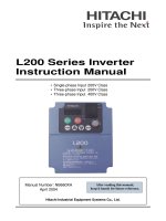
Storage and installation
Storage: If the inverter isn’t installed immediately, it should be stored in a clean and
dry location at ambient temperatures from 20℃ to 55℃. The surrounding air must be
free of corrosive contaminants.
Installation place: Places where the peripheral temperature is from -10℃ to 40℃,
and where the relative humidity is 90% or less. Avoid installing at places where there
is dust, iron particles, corrosive gas, water spray, direct sunlight or too much vibration.
And places where has good ventilation.
10 cm min
10cm
min
10cm
min
CT-2000EV
Website :www.viet-trung.com.vn
Đ/c: 194-Nguyễn Trãi-Võ Cường-TP Bắc Ninh
4
CTY TNHH TỰ ĐỘNG HÓA VIỆT TRUNG
02413.281.181-0989.984.666
10 cm min
4
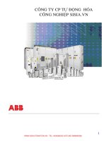
Exterior dimension: (Unit: mm)
CT2002EV-A75、CT2002EV-1A5、CT2004EV-A75、CT2004EV-1A5
Website :www.viet-trung.com.vn
Đ/c: 194-Nguyễn Trãi-Võ Cường-TP Bắc Ninh
5
CTY TNHH TỰ ĐỘNG HÓA VIỆT TRUNG
0989.984.666
02413.281.181-
CT2002EV-2A2、CT2002EV-3A7、CT2004EV-2A2、CT2004EV-3A7
5
Installation
Chapter 1 Installation
1.1 Wiring Diagram
◆ Wiring the master circuit and control circuit:
Wire according to the standard connection diagram. On using the external
sequence control, please use small signal relay or double terminal relay to avoid
relay terminal malfunction.
◆ Signal wire
The signal circuit uses either shielded pairs or twisted pairs, should be wired
either using a wiring duct separated from that for the power circuit, or with the
wiring conduit isolated as much as possible.
◆ Wiring between the master circuit and motor
Website :www.viet-trung.com.vn
Ninh
Đ/c: 194-Nguyễn Trãi-Võ Cường-TP Bắc
6
CTY TNHH TỰ ĐỘNG HÓA VIỆT TRUNG
02413.281.181-0989.984.666
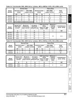
Connect the master circuit, by wiring according to the master circuit terminal
connection diagram. Care is required not to make a mistake when connecting
the input and output terminals, wiring error will cause inverter damage.
Specifications of master circuit path and NFB are as following:
Voltage ( V )
Type
NFB ( A )
CT2002EV-A75
10
2.0
CT2002EV-1A5
15
2.0
*CT2002EV-5A5
40
5.5
*CT2002EV-7A5
40
5.5
CT2004EV-1A5
10
2.0
CT2004EV-2A2
10
2.0
*CT2004EV-5A5
15
3.5
*CT2004EV-7A5
20
5.5
Standard wiring
( mm2 )
220V
CT2002EV-2A2
20
2.0
CT2002EV-3A7
30
3.5
380-460
CT2004EV-3A7
“*”
15
3.5
Under development
6
Installation
1.2 Reactor ( ACL )
The master purpose for fitting A.C.L. at the R.S.T. input side is to curb
instantaneous current and to improve ratio, it should be fitted the A.CL to R.S.T.
input side under the following circumstance:
A. Where power system capacity is over 500KVA.
B. Using the thyrister, phase advance capacity etc. For the same power supply.
Website :www.viet-trung.com.vn
Đ/c: 194-Nguyễn Trãi-Võ Cường-TP Bắc Ninh
7
CTY TNHH TỰ ĐỘNG HÓA VIỆT TRUNG
02413.281.181-0989.984.666
Inductance of Power side from R.S.T of Inverter(A.C.L):
Voltage ( V )
Inductance
rms )
Current Value ( A
Type
220
380-460
CT2002EV-A75
6
1.8 mH
CT2002EV-1A5
10
1.1 mH
CT2002EV-2A2
15
0.71 mH
CT2002EV-3A7
20
0.53 mH
*CT2002EV-5A5
30
0.35mH
*CT2002EV-7A5
40
0.26mH
CT2004EV-1A5
5
4.2 mH
CT2004EV-2A2
7.5
3.6 mH
CT2004EV-3A7
10
2.2 mH
*CT2004EV-5A5
15
1.41mH
*CT2004EV-7A5
20
1.0mH
“*”
Under development
Website :www.viet-trung.com.vn
Đ/c: 194-Nguyễn Trãi-Võ Cường-TP Bắc Ninh
8
CTY TNHH TỰ ĐỘNG HÓA VIỆT TRUNG
02413.281.181-0989.984.666
7
Installation
1.3 Brake resistor standard of usage
CT2000EV series inverter contain brake resistor, P、PR terminals can be
connected external brake resistor. The sizes of brake resistors refer to the
table.
If inertia is too large or cycle of discharge is higher, user can increase wattage
of resistor.
Voltage ( V )
220
Type
Brake resistor standard
CT2002EV-A75
120 Ω
80 W
CT2002EV-1A5
80 Ω
160 W
CT2002EV-2A2
60 Ω
250 W
Remark
380-460
CT2002EV-3A7
36 Ω
400 W
*CT2002EV-5A5
24Ω
500W
*CT2002EV-7A5
18Ω
750W
CT2004EV-1A5
360 Ω
300 W
CT2004EV-2A2
250 Ω
500 W
CT2004EV-3A7
150 Ω
800 W
*CT2004EV-5A5
100Ω
500W
*CT2004EV-7A5
75Ω
800W
“*”
Under development
Website :www.viet-trung.com.vn
Đ/c: 194-Nguyễn Trãi-Võ Cường-TP Bắc Ninh
9
CTY TNHH TỰ ĐỘNG HÓA VIỆT TRUNG
02413.281.181-0989.984.666
8
Installation
1.4 Standard external connection diagram
Website :www.viet-trung.com.vn
Đ/c: 194-Nguyễn Trãi-Võ Cường-TP Bắc Ninh 10
CTY TNHH TỰ ĐỘNG HÓA VIỆT TRUNG
02413.281.181-0989.984.666
9
Website :www.viet-trung.com.vn
Đ/c: 194-Nguyễn Trãi-Võ Cường-TP Bắc Ninh 11
CTY TNHH TỰ ĐỘNG HÓA VIỆT TRUNG
02413.281.181-0989.984.666
Installation
◆ Terminals arrangement
RA
SG RB
TA
IN1
IN3
DI1
DI3
DI5 FR
C NO
0V
TB
VOU
IN2
+10V
DI2
DI4
RR COM NC
Analog in/out terminal
Operation
Control
Multi-function
MODBUS
Multi-function input
terminal
Output terminal
Recharge lamp
Communication terminal
terminal
P
PR
R
U
S
V
T
W
E
Terminal arrangement ( 220V inverter 3.7kW shown as above )
Website :www.viet-trung.com.vn
Ninh
Đ/c: 194-Nguyễn Trãi-Võ Cường-TP Bắc
12
CTY TNHH TỰ ĐỘNG HÓA VIỆT TRUNG
02413.281.181-0989.984.666
MODBUS
Communication
Analog in/out terminal
VOUT
Multifunction input
SGOperation
RA RB
Terminal
Multifunction output
Terminal
Terminal
IN2
+10V
DI2
DI4
RR COM
NC
IN1
IN3
DI1
DI3
DI5
C
FR
NO
TA TB 0V
Recharge
Lamp
R
S
T
E
P PR
U
V
W
Terminal arrangement ( 220V inverter 1.5kW shown as above)
10
Installation
1.5 Terminal Specification Description
Classification
Terminal
symbol
Terminal name
Specification
3-phase AC power input:
R.S.T
AC power input terminal.
200~230V
50/60Hz
Website :www.viet-trung.com.vn
Ninh
Đ/c: 194-Nguyễn Trãi-Võ Cường-TP Bắc
13
CTY TNHH TỰ ĐỘNG HÓA VIỆT TRUNG
380~460V
02413.281.181-0989.984.666
50/60Hz
Master Circuit
U.V.W
Inverter output terminal.
3-phase induction motor.
Ground Terminal.
Ground Terminal of inverter.
Breaking resistor connecting
terminal.
Connected with brake resistor.
+10V power output.
Provide +10VDC 30mA power.
P、PR
E
+10V
0V
Common of analog input/
output.
Common of analog input/ output terminal.
Analog input/
output terminal
IN1
Multi-function analog input 1.
4~20mA input.
IN2
Multi-function analog input 2.
0~10V input.
VOUT
IN3
Master speed analog input 3.
0~10V input.
Multi-function analog output
terminal.
0~10V 5mA output.
DI1
DI2
Multi-function analog input terminal1.
Multi-function analog input terminal 1.
Multi-function analog input terminal
Multi-function analog input terminal 1.
DI3
Multi-function analog input terminal 1.
DI4
Multi-function analog input terminal 1.
DI5
Multi-function input terminal common.
COM
DC +24V 8mA Photocoupler isolation.
Connect with operation control terminal COM common.
Operation control terminal
RR
Reverse / stop terminal.
ON: reverse ; OFF: stop
FR
ON: forward ; OFF: stop
COM
Forward / stop terminal.
Operation control terminal.
Multi-function input and Operation control terminal common.
Multi-function analog output
Website :www.viet-trung.com.vn
Đ/c: 194-Nguyễn Trãi-Võ Cường-TP Bắc Ninh 14
CTY TNHH TỰ ĐỘNG HÓA VIỆT TRUNG
NO
Multi-function output contact A.
NC
Multi-function output contact B.
02413.281.181-0989.984.666
240VAC 5A
28VDC 10A
Multi-function output contact common.
contact
C
Multi-function output terminal contact
common.
TA
RS422 T+.
MODBUS Communication terminal
RS422 T+ or RS485 + terminal.
TB
RS422 T -.
RS422 T - or RS485 – terminal.
RA
RS422 R+.
RS422 R+.
RB
RS422 R -.
RS422 R -.
SG
Shield grounding terminal.
Provide shield grounding.
11
Installation
1.6 Option card standard wiring diagram
◆ Option card
Up to option card could be mounted in the CT2000EV, the master functions of
option card provides PG input terminal、2 sets of 12 bits analog input、2 sets of 12
bits analog output、1 set of P.W.M input terminal, and CAN BUS communication
interface.
◆ Option card standard wiring diagram
3φ AC 200V (400V)
INVERTER
CT2000EV
R
U
Website :www.viet-trung.com.vn
Đ/c: 194-Nguyễn Trãi-Võ Cường-TP Bắc Ninh 15
CTY TNHH TỰ ĐỘNG HÓA VIỆT TRUNG
S
T
02413.281.181-0989.984.666
V
W
PG
IM
Option Card
ENCODER
OPTION
E
E
+V
0V A+ AB+ BP+ P+V
-V
AI1
AI2
AO1
AO2
0V
PG Signal input
5V/12V
P.W.M signal input
5~10V 15mA
0.2~33KHz
VR
Multi-function
Input/ output terminal
VR
0~10V IN/OUT
± 10V IN/OUT
Website :www.viet-trung.com.vn
Đ/c: 194-Nguyễn Trãi-Võ Cường-TP Bắc Ninh 16
CTY TNHH TỰ ĐỘNG HÓA VIỆT TRUNG
02413.281.181-0989.984.666
Shielded pairs or twisted pairs
12
Installation
◆ Option card terminal arrangement
ER12
+V
0V
-V
AI1
AI2
A01
A02
P+
P+V
A+
0V
B+
Website :www.viet-trung.com.vn
Đ/c: 194-Nguyễn Trãi-Võ Cường-TP Bắc Ninh 17
CTY TNHH TỰ ĐỘNG HÓA VIỆT TRUNG
A-
02413.281.181-0989.984.666
B-
Grounding
terminal
Analog input/output Terminal
INPUT *2
OUTPUT *2
P.W.M
Input terminal
PG( encoder)
Signal input terminal
1.7 Option card terminal Function specification
Classification
Symbol of
terminal
Name of terminal
Specification
+V
+10V power output.
offer +10VDC 10mA power.
-V
-10V power output.
offer -10VDC 10mA power.
Analog input/
output terminal
0V
AI1
AI2
AO1
Analog input/ output terminal common.
Multi-function analog input 1.
Multi-function analog input 2.
Multi-function analog output 1.
Multi-function analog output 2.
AO2
Analog in/ output terminal common, please do not mix up with others.
By constant setting 0~10V or ±10V input.
By constant setting 0~10V or ±10V
10mA output.
Website :www.viet-trung.com.vn
Đ/c: 194-Nguyễn Trãi-Võ Cường-TP Bắc Ninh 18
CTY TNHH TỰ ĐỘNG HÓA VIỆT TRUNG
02413.281.181-0989.984.666
13
Installation
Option card terminal Function specification (continued)
Classification
Symbol of
Name of terminal
terminal
Specification
+V
PG power output.
12 VDC 200mA output *.
0V
PG Signal common.
PG Signal common, please don’t mix
up with others.
PG Signal input
terminal
A+
P.W.M input
A phase positive.
A-
A phase negative.
B+
B phase positive.
B-
B phase negative.
P+
P.W.M input positive.
Line driver PG Signal input.
Input 0.2~32kHz、5~10VDC 、8mA~
terminal
PP.W.M input negative.
15mA P.W.M signal.
* Output is 5 VDC 200mA when the resistor of ER12 was removed from option card.
Website :www.viet-trung.com.vn
Đ/c: 194-Nguyễn Trãi-Võ Cường-TP Bắc Ninh 19
CTY TNHH TỰ ĐỘNG HÓA VIỆT TRUNG
02413.281.181-0989.984.666
14
Operation and autotuning
Chapter 2 Operation and autotuning
◆ Keypad
Unit indicator
V : Voltage
Ampere
Hz: Frequency
A :
Operation mode display
FWD :Lit when forward, forward decel is flash
REV :Lit when reverse, reverse decel is flash
Status indicator
DISP:
Monitor mode
V
Hz
A
DISP
FWD
Website :www.viet-trung.com.vn
Đ/c: 194-Nguyễn Trãi-Võ Cường-TP Bắc Ninh 20
CTY TNHH TỰ ĐỘNG HÓA VIỆT TRUNG
02413.281.181-0989.984.666
REV
PLC
Special control mode indicator
Function auto operation
PLC
ALARM:
Error occurred
ALARM
A.TUNE
Digital Operator
KP-202
Procedure control
Operation control key
FWD:
Forward REV :
Reverse STOP: Stop
FWD
REV STOP
PROG
SET
READ
A.TUNE: Motor auto detect
Keypad analog main speed
Setting
Function key
Execute operations
◆ Keypad display specification
Key
Name
FWD
REV
Forward key
Reverse key
STOP
PROG/SET
READ
Stop key
Function key
Read key
▲
Right shift key
Increment key
Website :www.viet-trung.com.vn
Function
Forward operation
Reverse operation
Stop operation、faulty reset
Monitor/ input mode swich、constant setting
Read/ exit content of constant
Nonius right and shift
Increment
Đ/c: 194-Nguyễn Trãi-Võ Cường-TP Bắc Ninh 21
CTY TNHH TỰ ĐỘNG HÓA VIỆT TRUNG
▼
Decrement key
02413.281.181-0989.984.666
Decrement
15
Operation and autotuning
2.1 Operation of monitor
◆ All mode operation
The operation modes of CT2000EV equipped monitoring and input modes, this
section described mode and switching between modes.
◆ Monitoring operation
A. Modify Monitoring
DISP
ALARM
Hz
A
FW D
REV
PLC
A.TUNE
DISP indicator lit means monitoring
item.
When stop operation, display operation command.
↓ Press READ key
DISP
Hz
A
ALARM
FW D
REV
Website :www.viet-trung.com.vn
Đ/c: 194-Nguyễn Trãi-Võ Cường-TP Bắc Ninh 22
CTY TNHH TỰ ĐỘNG HÓA VIỆT TRUNG
02413.281.181-0989.984.666
PLC
A.TUNE
Monitoring item is U1-01.
Select monitoring items by pressing
▲ and ▼ key.
↓ Press ▲ key
DISP
Hz
A
ALARM
FW D
REV
PLC
A.TUNE
Set modifying monitoring as U1-02.
Select monitoring items by pressing
▲ and ▼ key.
↓ Press READ key
Hz
PLC
A
DISP
FW D
REV
Enter U1-02 monitoring (output frequency).
ALARM
A.TUNE
16
Operation and autotuning
B. Detect fault status
Website :www.viet-trung.com.vn
Đ/c: 194-Nguyễn Trãi-Võ Cường-TP Bắc Ninh 23
CTY TNHH TỰ ĐỘNG HÓA VIỆT TRUNG
02413.281.181-0989.984.666
DISP
ALARM
Hz
A
FW D
REV
PLC
A.TUNE
DISP indicator lit means monitoring
item.
When stop operation, display operation command.
↓ Press READ key
DISP
Hz
ALARM
A
FW D
REV
PLC
A.TUNE
Monitoring is in the process of U1-01
Press
key to shift the nonius.
↓ Press
key
DISP
ALARM
Hz
A
FW D
REV
PLC
A.TUNE
The nonius shift to secondary.
Press ▲ key to select monitoring
Website :www.viet-trung.com.vn
Đ/c: 194-Nguyễn Trãi-Võ Cường-TP Bắc Ninh 24
CTY TNHH TỰ ĐỘNG HÓA VIỆT TRUNG
02413.281.181-0989.984.666
U1 is ordinary monitoring and U2 is fault status.
↓ Press ▲ key
DISP
ALARM
A
Hz
FW D
REV
PLC
A.TUNE
U2-01 is in the process of monitoring
Press ▲ and ▼ key to select
monitoring.
↓ Press READ key
DISP
A
Hz
FW D
REV
Enter U2-01, fault status shows OC (over current).
PLC
ALARM
A.TUNE
17
Operation and autotuning
C. Press operation key under any situation
Hz
A
DISP
FW D
REV
Website :www.viet-trung.com.vn
Đ/c: 194-Nguyễn Trãi-Võ Cường-TP Bắc Ninh 25