Tài liệu biến tần ENC EDS1000 manual
Bạn đang xem bản rút gọn của tài liệu. Xem và tải ngay bản đầy đủ của tài liệu tại đây (1.39 MB, 186 trang )
ISO9001:2008 Quality Management System Authentication
CE Authentication
EDS1000 series
EDS1100/EDS1300 series
Universal inverter
Ver.4.0
Service manual
SHENZHEN ENCOM ELECTRIC TECHNOLOGIES CO.,LTD.
Print version:V4.0-A7
Foreword
Encom
products
are
designed
and
produced
according
to
EN61800-5-1: 2007, EN61010-1:2010; EN61800-3: 2004+A1:2012 standards
under ISO9001:2008 quality management system.
Thank you for purchasing EDS1000 series multi-function universal inverter
from our company Shenzhen Encom Electric Technologies CO., LTD.
1. EDS1000 series can fulfill all kinds of demand for general-purpose inverter
by advanced control manner which make high torque high precision and
wide-range speed regulation drive be available. EDS1000 is organic combine of
customer’s general need and industrial requirement to provide practical PI adjuster,
simple PLC, programmable input output terminal control, long-distance
synchronous control, impulse frequency provision and other special inverter
control with powerful function for customer and to provide highly-integrated
incorporative solution of high value for reducing system cost and improving
system reliability for device manufacturing and automatization engineering
customers.
EDS1000’s big torque low noise and low electromagnetic disturbance during
operation can fulfill customer’s environmental protection requirement by space
voltage vector PWM control technique, speed sensorless vector control
technology and electromagnetic compatibility unitary design.
2. EDS1100 series inverter specialized for drawing machine is a kind of
inverter in cable industry for winding and rewinding control. Its internal real-time
computing module can automatically identify the coil diameter of the receive
volume, the wire diameter of drawing wire , according to the changes of winding
and rewinding of the roll diameter, automatically adjust the output frequency of
winding and rewinding of the inverter, to keep constant tension of winding and
rewinding cable.
Drawing machine can divide into large drawing machine, medium drawing
machine, slender drawing machine and micro drawing machine other four,
composes of drawing and taking-up two parts. To improve the quality of cable and
lower the cost, drawing machine is general from single frequency control to
dual-frequency control, and now most of the dual-frequency control is generally
used external PID control board, the shortcomings of this approach are: the
control parameters of PID board is difficult to debug, the control performance
depends on the level of debugging skill; Too many components and adjustable
potentiometers on the PID board are more prone to damage, repair and
maintenance costs are high.
EDS1100 series inverters specialized in drawing machine adopt a unique
control method, independently form dual-frequency digital PID control system,
automatically identify the diameter of reel roll, the mechanical transmission ratio,
cable diameter, automatically adjust the PID parameters, track the speed of the
host, that is to pole zero of the tension balance when it powers on (middle point),
is a real sense of the fool-type inverter special for drawing machine. As long as
the correct general electrical wiring, you can work. Whether it is an empty plate,
half plate, full plate, or the low speed, medium speed, high speed, which ensures a
smooth start, smooth operation, constant tension when wire drawing machine at
work, as well as achieving start, stop at any time. Complete replacement of
external PID board to make the system more compact, cheaper, easier to maintain,
while controlling effect is more stable.
In order to maintain constant tension of the close and put, the inverter special
for drawing machine is to be in a relatively short period of time acceleration and
deceleration. During the process of acceleration and deceleration, the inverter
must provide larger start-up current, braking current and resulted in higher DC bus
voltage, thus it needs external braking resistor.
Appendix 1 only makes instructions of controlling function of the inverter
special for drawing machine, please use with EDS1000 manual simultaneously
when operating.
Assembling wiring, parameter setting, troubleshooting and daily maintenance
notices are available in this manual. To make sure that you can correctly assemble
and operate EDS1000 series inverters to exert their excellent performance, please
read this user manual detailed before you assemble the device and conserve the
manual appropriately before the end-user get them.
Please contact our office or dealer in all places at any moment if you have any
doubts or special demands when using these inverters, and you can also contact
our after service center in our Headquarters directly. We will serve you with all
our heart.
We reserve our right to notice you if we change contents of this manual.
CONTENTS
1
Safety information and use notice points
1.1
Safety precautions
1.2
Use range
1.3
Use notice points
1.4
Scrap notice points
2
3
Type and specification of the inverter
1
1
2
2
3
4
4
2.1
Incoming inverter inspect
2.2
Type explanation
2.3
Nameplate explanation
2.4
Series type explanation
2.5
Appearance and parts name explanation
2.6
Outer size and gross weight
2.7
Outer size of key board and its fixing box
6
6
8
2.8
Product technic index and spec
8
Installation and wiring
3.1
Installation ambient
3.1.1
Demand for installation ambient
3.1.2
Installation direction and space
3.2
Parts disassembly and installation
3.2.1
Key board disassembly and installation
3.2.2
Plastic/metal cover disassembly and installation
3.3
Wiring notice points
3.4
Main loop terminal wiring
3.4.1
Connection between inverter and fitting parts
3.4.2
Main loop terminal wiring
3.5
Basic running wiring diagram
3.6
Control loop collocation and wiring
3.6.1
Location&function of terminal and slide switch
4
4
5
11
11
11
11
12
12
12
13
14
14
16
18
19
19
3.6.2
Explanation for control panel terminal
20
3.6.3
Analog input output terminal wiring
3.6.4
Communication terminal wiring
3.7.1
Restraining to noise disturbance
23
25
27
27
3.7.2
Locale wiring and earthing
29
3.7.3
Relation of long-distance wiring and current leak
3.7
Installation guide for anti-jamming
and the countermeasure
3.7.4
Installation demand for electromagnetic on-off
electronic device
4
Run and operation explanation for inverter
4.1
Run of inverter
4.1.1
Running order channels
4.1.2
Frequency-provision channel
4.1.3
Work state
4.1.4
Run mode
4.2
29
Operation and use of key board
29
31
31
31
31
31
32
34
4.2.1
Keypad layout
34
4.2.2
Keypad function description
4.2.3
LED and indicator light
34
35
4.2.4
Key board display status
4.2.5
Method for operating keypad
4.3
Inverter electrification
4.3.1
Check before electrification
4.3.2
First electrification
5
Function parameter schedule graph
5.1
Symbol description
5.2
Function parameter schedule graph
6
Detailed function description
6.1
Basic run function parameter group: F0
35
37
41
41
41
42
42
42
57
57
6.2
Start, stop, braking function parameter group:F1
6.3
Auxiliary run function parameter group: F2
6.4
Closed-loop run function parameter group: F3
6.5 Simple PLC function parameter group:F4
6.6 Terminal correlative function parameter group: F5
6.7
Traverse special function parameter group: F6
6.8
Frequency provision function parameter group: F7
6.9
Motor and vector control parameter group: F8
6.10
Protection function parameter group:F9
6.11
Failure record function parameter group: Fd
6.12
Password and manufacturer function parameter group: FF
7
Troubleshooting
7.1
Failure and countermeasure
7.2
Failure record lookup
7.3
Failure reset
8
Maintenance
8.1
Routine maintenance
8.2
Inspection and replacement of damageable parts
8.3
Repair guarantee
8.4
Storage
9
Fitting parts
9.1
Communication subassembly
9.1.1
Long-distance operation key board
9.1.2
Communication cable
10
10.1
Examples
Common speed regulation running
10.2 Terminal control running
10.3
Multi-step speed control running
10.4
Closed-loop control system
10.5
Consecutive action running
10.6
Application to constant pressure water supply
62
64
73
82
87
99
101
104
105
108
109
110
110
113
113
114
114
114
115
115
116
116
116
116
117
117
118
119
120
121
122
Modbus communication protocol
128
Appendix1 EDS1100 drawing machine inverter manual
135
154
11
Appendix2 The manual of EDS1300 middle frequency inverter
Appendix3 Serial port RS485 communication protocol (need
customized special process)
Appendix4 Braking resistance
168
178
www.enc.net.cn/en Tel/Fax:86-755-26984485/26985120
1
1 Safety information and use notice points
Safety information and use notice points
In order to ensure the safety of your personal and equipment, before using the
inverter, please read this chapter of contents conscientiously.
1.1
Safety precautions
There are three kinds of safe relevant warnings in this service manual, they
are as follows:
!
This symbol explains items that need to be paid attention to when being
operated.
This symbol is briefed on some useful information.
note
!
This symbol briefs on: If does not operate on request, may cause death,
severely injured or serious property loss.
!
Forbid user directly power off when the inverter is under running, accelerating or
decelerating, must only ensure that the drive has been completely shut down or in
standby situation can perform power off operation. Otherwise, the users themselves
afford the damage of the inverter, equipment damage and personal accident.
!
(1) Forbid to connect U, V, W output end to AC power supply, otherwise cause the
complete damage of the inverter.
(2) Don't make P- and P + short-circuited, otherwise cause the inverter to be damaged.
(3) The inverter is forbidden to install on the flammables, otherwise have danger of fire.
(4) Don't install it in the environment with explosive gas, otherwise have danger of
causing explosion.
(5) After connecting main loop, should carry on insulating treatment to bare wiring end,
otherwise have danger of getting an electric shock.
(6) If being connected to the power supply, don't operate the inverter with moist hands,
otherwise have danger of getting an electric shock.
(7) The ground terminal of the inverter must be grounded well.
(8) Inverter being connected to power supply, please don't open cover and carry on
wiring, can connect the wire or check only after closing power for10 minutes.
(9) Only qualified personnel may carry on wiring and forbid leaving over any
conductive thing in machine, otherwise have danger of getting an electric shock or
causing damage of the inverter.
(10) Inverter stored for over 2 years, should be stepped up gradually with voltage
regulator first while having the electricity, otherwise have danger of getting
electric shock and explosion.
1
www.enc.net.cn/en Tel/Fax:86-755-26984485/26985120
1 Safety information and use notice points
(1)
!
1.2
It is prohibited that connect AC 220V signal to control ends except TA, TB, TC,
otherwise have danger of damaging property.
(2) If the inverter is damaged or without all parts, please don't install and operate it,
otherwise have danger of fire or cause personnel to be injured.
(3) When installing, should choose a place where can endure the inverter, otherwise
have danger of injuring personnel or damaging property while falling down.
Use range
(1) This inverter is only suitable for three phases AC asynchronous motor in
general industrial field.
(2) While applying inverter to such equipments that relate much to the life, great
property, safety devices etc., must handle cautiously, and consult with
producer, please.
(3) This inverter belongs to the control device of general industrial motor, if used
in dangerous equipment, must consider the security safeguard procedures
when the inverter breaks down.
1.3
Use notice points
(1) EDS1000 series inverter is voltage-type inverter, so temperature, noise and
vibration slightly increasing compared to power source running when using,
belongs to normal phenomenon.
(2) If need to run for a long time with constant torque of low-speed, must select
motor of frequency conversion for use. Use general asynchronous AC motor
when running at a low speed, should control temperature of the motor or carry
on heat dissipation measure forcedly, so as not to burn the generator.
(3) Such mechanical device needing lubricating as the gearbox and gear wheel,
etc., after running at a low speed for a long time, may be damaged as
lubrication result become poor, please take necessary measure in advance.
(4) When the motor running with frequency above specified, besides considering
the vibration, noise increase of the motor, must also confirm speed range of
the motor bearing and the mechanical device.
(5) For hoist and great inertia load, etc., the inverter would shut off frequently due
to over-current or over-voltage failure, in order to guarantee normal work,
should consider choosing proper brake package.
(6) Should switch on/off the inverter through terminal or other normal order
channels. It is prohibited that switch on/off the inverter frequently by using
strong electric switch such as magnetic control conductor, otherwise will
cause the equipment to be damaged.
(7) If need to install such switch as the magnetic control conductor, etc. between
2
www.enc.net.cn/en Tel/Fax:86-755-26984485/26985120
1 Safety information and use notice points
inverter output and the motor, please guarantee the inverter is switched on/off
without output, otherwise may damage the inverter.
(8) The inverter may meet with mechanical resonance of the load within certain
range of frequency output, can set up jumping frequency to evade.
(9) Before using, should confirm the voltage of the power is within the working
voltage range allowed, otherwise should vary voltage or order special inverter.
(10) In the condition of altitude above 1000 meters, should use the inverter in
lower volume, reduce output current by 10% of specified current after each
1500 meters height increasing.
(11) Should make insulation check to the motor before using it for the first time
or after a long time placement. Please inspect with 500V voltage-type
megohm meter according to method shown as graph 1-1 and insulation
resistance should not be smaller than 5 M , otherwise inverter may be
damaged.
(12) To forbid assembling capacitor for improving power factor or lightningproof
voltage-sensible resistance etc., otherwise will cause malfunction trip of the
inverter or damage of the parts, shown as graph 1-2.
EDS1000
U
VW
After wiring, short-circuit U,
V, W to measure insulation
resistance.
motor
U
EDS2000
EDS1000 V
W
M
Grounding part
Megohm meter
Fig.1-1 motor insulation measure
1.4
Fig.1-2 capacitor at output side forbidden
Scrap notice points
When disposing scrap inverter and its parts, please note:
(1) The unit: please discard as industrial useless.
(2)
Electrolytic capacitor: when burning the inverter electrolytic capacitor
in it may explode.
(3) Plastic: when plastic, rubber parts etc. in the inverter are burning, they
may bring bad, poisonous gas, so please be ready to safeguards.
3
www.enc.net.cn/en Tel/Fax:86-755-26984485/26985120
2
2.1
2 Type and specification of the inverter
Type and specification of the inverter
Incoming inverter inspect
(1) Check if there is damage during transportation and inverter itself has damage or
fall-off parts.
(2) Check if parts presented in packing list are all ready.
(3) Please confirm rated data of the inverter is in line with your order requirement.
Our product is guaranteed by strict quality system during manufacturing,
packing, transportation etc., please contact our company or local agent rapidly if
some careless omission or mistake arise, we’ll deal with it as soon as possible.
2.2
Type explanation
EDS1000- 4 T 0022 G / B
Inverter serial
code
No.
G
P
Inverter type
2
4
7
220V
380V
690V
code
Code
Input volt.
0004
0.4
Three phase
Single phase
0007
0.75
0750
75
Fig. 2-1
Fitting part
B
built-in brake unit
E
remote-control keypad
Motor power
(KW)
…
…
Volt. grade
T
S
code
General
Special
code
type description
If the inverter hasn’t relevant content or can be defaulted, code after “/” will be ignored.
note
2.3
Nameplate explanation
Nameplate presented as figure 2-2 with type and rating data at the bottom of
inverter right side.
Series Name
Type
Rated input volt. and frequency
Output volt. And frequency
Output apparent power and current
Serial No.
Manufacturer
Fig.2-2 Nameplate
4
www.enc.net.cn/en Tel/Fax:86-755-26984485/26985120
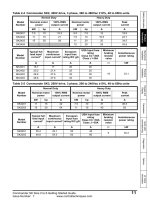
2.4
2 Type and specification of the inverter
Series type explanation
Table 2-1 series type explanation
Inverter type
(G: general with constant torque:
P: special for blower water pump)
EDS1000/1300-2S0004
Input
voltage
(V)
EDS1000/1300-2S0007
Single
phase
220V
EDS1000/1300-2S0015
Rated power
(KVA)
Rated output
current (A)
Adapted motor
(KW)
1.1
3
0.4
1.8
4.7
0.75
2.8
7.5
1.5
3.8
10
2.2
EDS1000-2S0037
5.6
17
3.7
EDS1000-2T0007
1.1
4
0.75
2.1
7
1.5
3.2
10
2.2
5.3
15
3.7
EDS1000-2T0055
7.8
24
5.5
EDS1000-2T0075
10.5
32
7.5
EDS1000/1100/1300-4T0007G/0015P
1.5/2.4
2.3/3.7
0.75/1.5
EDS1000/1100/1300-4T0015G/0022P
2.4/3.3
3.7/5
1.5/2.2
EDS1000/1100/1300-4T0022G/0037P
3.3/5.6
5/8.5
2.2/3.7
EDS1000/1100/1300-4T0037G/0055P
5.6/8.6
8.5/13
3.7/5.5
EDS1000/1100/1300-4T0055G/0075P
8.6/11
13/17
5.5/7.5
EDS1000/1100/1300-4T0075G/0110P
11/17
17/25
7.5/11
17/21.7
25/33
11/15
21.7/25.7
33/39
15/18.5
EDS1000/1100/1300-4T0185G/0220P
25.7/29.6
39/45
18.5/22
EDS1000/1100/1300-4T0220G/0300P
29.6/39.5
45/60
22/30
EDS1000/1100/1300-4T0300G/0370P
39.5/49.4
60/75
30/37
EDS1000/1100/1300-4T0370G/0450P
49.4/60
75/91
37/45
EDS1000-4T0450G/0550P
60/73.7
91/112
45/55
EDS1000-4T0550G/0750P
73.7/99
112/150
55/75
EDS1000-7T0110G/0150P
17/21.7
15/18
11/15
EDS1000-7T0150G/0185P
21.7/25.7
18/22
15/18.5
EDS1000-7T0185G/0220P
25.7/29.6
22/28
18.5/22
EDS1000-7T0220G/0300P
29.6/39.5
28/35
22/30
EDS1000-7T0300G/0370P
39.5/49.4
35/45
30/37
EDS1000-7T0370G/0450P
49.4/60
45/52
37/45
60/73.7
52/63
45/55
73.7/99
63/86
55/75
99/116
86/98
75/90
EDS1000/1300-2S0022
EDS1000-2T0015
EDS1000-2T0022
EDS1000-2T0037
EDS1000/1100/1300-4T0110G/0150P
EDS1000/1100/1300-4T0150G/0185P
EDS1000-7T0450G/0550P
EDS1000-7T0550G/0750P
EDS1000-7T0750G/0900P
Three
phase
220V
Three
phase
380V
Three
phase
690V
EDS1000-7T0900G/1100P
116/138
98/121
90/110
EDS1000-7T1100G/1320P
138/167
121/150
110/132
EDS1000-7T1320G/1600P
167/200
150/175
132/160
EDS1000-7T1600G/2000P
200/250
175/215
160/200
EDS1000-7T2000G/2200P
250/280
215/235
200/220
5
www.enc.net.cn/en Tel/Fax:86-755-26984485/26985120
2.5
2 Type and specification of the inverter
Appearance and parts name explanation
digital
potentiometer
LED display
keypad
LED display
digital potentiometer
Upper cover plate
keypad
connection terminal
Control
cable
nameplate
inlet
bottom fitting hole
ventilation hole
Control cable inlet
Power supply input end
output end
ventilation hole
Fig. 2-3 Parts name sketch
2.6
nameplate
Power supply input end
output end
Outer size and gross weight
Fig.a
Fig.b
Fig.d
H
Fig.c
D
Fig.e
Fig.2-4 Outer dimension
6
W
Fig.f
www.enc.net.cn/en Tel/Fax:86-755-26984485/26985120
Table 2-2
2 Type and specification of the inverter
EDS1000-2S0004~EDS1000-4T0750P mounting size
Fixing G.W.
A
B
W
H
D
D1
aperture
(mm) (mm) (mm) (mm) (mm) (mm) (mm) (kg)
Inverter type
(G: general; P: special)
EDS1000/1300-2S0004
EDS1000/1300-2S0007
EDS1000/1300-2S0015
EDS1000/1300-2S0022
EDS1000/EDS1100/1300-4T0007G/0015P
Fig.
110
160
125
170
123.2
135.5
4
2
Fig a
140
215
155
230
155
164
5
3.8
Fig b
EDS1000/EDS1100/1300-4T0015G/0022P
EDS1000/1100/1300-4T0022G/0037P
EDS1000-2S0037
EDS1000/1100/1300-4T0037G/0055P
EDS1000/1100/1300-4T0055G/0075P
EDS1000/1100/1300-4T0075G/0110P
EDS1000/1100/1300-4T0110G/0150P
EDS1000/1100/1300-4T0150G/0185P
EDS1000/1100/1300-4T0185G/0220P
EDS1000/1100/1300-4T0220G/0300P
EDS1000/1100/1300-4T0300G/0370P
EDS1000/1100/1300-4T0370G/0450P
EDS1000-4T0450G/0550P
EDS1000-4T0550G/0750P
EDS1000-2T0007
Inverter type
185
275
200
290
178
187
6
6.3
Fig b
135
330
218
345
210
221
7
10
Fig c
180
410
260
430
252
261
9
17
Fig c
200
485
280
505
252
261
9
23
Fig c
200
515
300
535
252
261
9
33
Fig c
EDS1000-2T0075 mounting size
A
(mm)
B
(mm)
W
(mm)
H
(mm)
D
(mm)
Fixing
D1
G.W.
aperture
(mm)
(kg)
(mm)
Fig.
110
160
125
170
123.2
135.5
4
2
Fig a
140
215
155
230
155
164
5
3.8
Fig b
185
275
200
290
178
187
6
6.3
Fig b
EDS1000-2T0007
EDS1000-2T0015
EDS1000-2T0022
EDS1000-2T0037
EDS1000-2T0055
EDS1000-2T0075
EDS1000-7T0110G~EDS1000-7T2000G mounting size
Inverter type
EDS1000-7T0110G/0150P
EDS1000-7T0150G/0185P
EDS1000-7T0185G/0220P
EDS1000-7T0220G/0300P
EDS1000-7T0300G/0370P
EDS1000-7T0370G/0450P
EDS1000-7T0450G/0550P
EDS1000-7T0550G/0750P
EDS1000-7T0750G/0900P
EDS1000-7T0900G/1100P
EDS1000-7T1100G/1320P
EDS1000-7T1320G/1600P
EDS1000-7T1600G/2000P
EDS1000-7T2000G/2200P
A
(mm)
B
(mm)
W
(mm)
H
(mm)
D
(mm)
Fixing
aperture
(mm)
Fig.
200
552
284
570
252.7
9
Fig e
280
620
420
650
300
9
Fig d
320
720
500
750
300
12
Fig d
400
790
590
820
372
12
Fig d
-
-
630
1200
500
-
Fig f
7
www.enc.net.cn/en Tel/Fax:86-755-26984485/26985120
2.7
2 Type and specification of the inverter
Outer size of keypad and its fixing box (unit: mm)
Fig.2-5 EN-KB5 outer size
Fig.2-6
EN-KB5 hole size
152.5
160
94
87.5
4
Fig.2-7 EN-KB6 outer size
2.8
EN-KB6 hole size
Product technic index and spec
Item
Rating volt., frequency
Input
Allowed work volt. range
output
8
Fig.2-8
Voltage
Item description
1 phase 220V grade, 1 phase 220V ,50Hz/60Hz;
3 phase 220V grade, 3 phase 220V ,50Hz/60Hz;
3 phase 380V grade, 3 phase 380V ,50Hz/60Hz;
3 phase 690V grade, 3 phase 690V ,50Hz/60Hz.
1 phase 220V grade: 200V~260V;
3 phase 220 V grade: 200V~260V;
3 phase 380 V grade: 320V~460V;
3 phase 690 V grade: 586V~760V
220V grade: 0~220V;
380V grade: 0~380V;
690V grade: 0~690V;
www.enc.net.cn/en Tel/Fax:86-755-26984485/26985120
Frequency
0Hz-400Hz
Over loading capacity
Control mode
Speed regulation range
Start-up torque
Running speed stable state
precision
1: 100
150% of rating torque at 1 Hz frequency
±0.5% of rating synchronous speed
Digital setting: max. frequency×±0.01% analog
setting: max.frequency×±0.5%
Analog setting
Frequency
Digital setting
resolution
Exterior impulse
precision : <100Hz 0.01Hz;
V/F curve (volt. frequency
characteristic)
0.1% of max. frequency
100Hz: 0.1Hz
0.5% of max. frequency
Automatic torque boost, manual torque boost
0.1%~12.0%
Set rating frequency randomly at range of
5~400Hz can choose constant torque, degressive
torque 1, degressive torque 2, degressive torque 3
and user-defined V/F in total 5 kinds of curve
2 modes: straight line accelerating decelerating and
S curve accelerating decelerating; 7 kinds of
Accelerating decelerating curve
accelerating decelerating time (unit minute/second
can be optioned), max. time 6000 minutes.
brake
Power consumption Interior or exterior brake resistance. 690 V grade
brake
haven’t build-in brake unit .
DC brake
Jog
Running
function
G type: 150% of rating current for1 minute 200%
of rating current for 0.5 second
P type: 120% of rating current for 1 minute
Speed sensorless slip vector control,
open loop V/F control
Frequency precision
Torque boost
Control
performance
2 Type and specification of the inverter
Optional start-up and stop action frequency 0~15Hz
action volt. 0~15% action time 0~20.0 s
Jog frequency range: 0.50Hz~50.00Hz; jog
accelerating decelerating time 0.1~60.0s can be set
Multisection speed running
Realized by interior PLC or control terminal
Interior PID controller
Be convenient to make closed-loop system
Optimize V/F curve automatically based on the load
Automatic energy save running
to realize power save running
Automatic volt. regulation
Can keep constant output volt. When power source
(AVR)
voltage varies.
Limit running current automatically to avoid
Automatic current limiting
frequent over-current which will cause trip
Key pad specified, control terminal specified, serial
Running order specified channel
port specified.
Digital provision, analog provision, impulse
Running frequency specified
provision, serial port provision, combined
channel
provision can be switched at any time by kinds of
method.
9
www.enc.net.cn/en Tel/Fax:86-755-26984485/26985120
pulse output channel
Analog output channel
Can display setting frequency, output frequency,
output voltage, output current etc.
Lock the button
Lock all or part of the buttons(analog potentiometer
can’t be locked)
Protection function
Over-current protection, over-voltage protection,
lack-voltage protection, over-heat protection,
over-load protection, etc.
Fitting parts
brake subassembly, remote-control keypad,
connecting cable for remote-control keypad etc.
ambient
configuration
!
10
Impulse square wave signal output of 0~20KHz
can realize output of physical parameter such as
setting frequency, output frequency etc.
2 channel of analog signal output thereinto AO1
channel can be 4~20mA or 0~10V and AO2
channel is 0~10V; through them the inverter can
realize output of physical parameter such as setting
frequency, output frequency etc.
LED display
keypad
note
2 Type and specification of the inverter
Use ambient
indoor not bare to sunlight no dust, no corrosive
gas, no flammable gas, no oil fog, no vapor, no
water drop or salt etc.
altitude
Lower than 1000m ,if higher than 1000m ,need to
reduce amount to use.
Ambient temperature
-10ºC~+40ºC(under ambient temperature 40ºC
~50ºC, please reduce the volume or strengthen heat
sink)
Ambient humidity
Smaller than 95%RH, no condensation water
vibration
Smaller than 5.9m/s²(0.6g)
Storage temperature
-40ºC~+70ºC
Defending grade
IP20
Cooling mode
By fan with automatic temperature control
Mounting mode
Wall hanging
To exert excellent performance of this inverter, please choose correct type and check
relevant content according to this chapter before wiring for use.
Must choose correct type, otherwise may cause abnormal running of the motor or
damage of the inverter.
www.enc.net.cn/en Tel/Fax:86-755-26984485/26985120
3
3.1
3 Installation and wiring
Installation and wiring
Installation ambient
3.1.1
Demand for installation ambient
(1) Installed in drafty indoor place ambient temperature within -10ºC~40ºC need
external compulsory heat sink or reduce the volume if temperature exceeds
40ºC.
(2) Avoid installing in place with direct sunlight, much dust, floating fibre and
metal powder.
(3) Forbid to install in place with corrosive, explosible gas.
(4) Humidity should be smaller than 95%RH without condensation water.
(5) Installed in place of plane fixing vibration smaller than 5.9m/s²(0.6g).
(6) Keep away from electromagnetic disturbance source and other electronic
apparatus sensible to electromagnetic disturbance.
3.1.2 Installation direction and space
(1) Normally the inverter should be mounted vertically, horizontal mounting will
seriously affect heat dissipation and the inverter must be used in lower
volume.
(2) Demand for minimum mounting space and distance please see Fig.3-1.
(3) When install multiple inverters up and down, must apply leading divider
between them, see fig. 3-2.
Fan
exhaust
Fan
exhaust
110mm or more
50mm
50mm
or more
or more
200mm or more
100mm
or more
100mm
or more
200mm or more
110mm or more
Fig. 3-1 mounting space
11
www.enc.net.cn/en Tel/Fax:86-755-26984485/26985120
3 Installation and wiring
inverter
Leading
divider
inverter
Fig. 3-2 mounting of multiple inverters
3.2
Parts disassembly and installation
3.2.1
Key board disassembly and installation
Mounting claw
(1) Disassembly
Let the forefinger press finger inlet on
the keypad depress fixing flexible plate
on the top lightly, draw it outward, then
Hook
Mounting claw
you can disassemble the keypad.
(2) Assembly
Fig.3-3 mounting sketch of keypad
First place the fixing hook at the bottom of keypad onto mounting claw on
keypad mounting hole, let forefinger press fixing flexible plate on top of
keypad and then push it inside, release it in proper location(after a crisp
sound), see Fig. 3-3.
3.2.2 Plastic/metal cover disassembly and installation
3.2.2.1 Plastic cover disassembly and installation:
(1) Disassembly
Put the finger into handle hole on the bottom of cover, lift it in force, till
buckle between cover and unit body off, draw the cover backward, then you
can disassemble the cover.
(2) Assembly
1> tilt the cover for 5~10 degree
2> put the mounting claw into relevant hole on the unit body and then press
downward in force, see fig. 3-4.
3.2.2.2 Metal cover disassembly and installation
12
www.enc.net.cn/en Tel/Fax:86-755-26984485/26985120
3 Installation and wiring
(1) Disassembly
First take off 2 screws at sides of the cover and move it a bit outward
horizontally, then tilt it at 15 degree and draw it outward at direction shown in
right figure, now you can take the cover off.
(2) Assembly
First put down the cover in parallel with unit body and make it just locked at
2 sides of the inverter, secondly force it ahead and make fixing part on its top
inserted into fixing slot of unit body, at last screw the cover and finish assembly
for the cover. As shown in Fig.3-5.
Fig. 3-4
disassembly and mounting
sketch
of plastic
cover
3.3 wiring
notice
points
3.3 Wiring notice points
!
Fig.3-5 disassembly and assembly
for metal cover
(1) Assure power cuf off completely for above 10 minutes before wiring otherwise have
danger of getting electric shock.
(2) Forbid connecting power wire to output U, V, W of the inverter.
(3) There is current leakage in the inverter and leak current of middle/high power inverter
is bigger than 5mA for safety reason inverter and motor must be earthed safely
commonly use 3.5mm² above copper wire as ground wire and ground resistance
smaller than 10Ω.
(4) Before shipment compression resistance test of the inverter is passed so user should
not conduct compression resistance test again.
(5) Should not assemble electromagnetic contactor and absorbing capacitance or other
absorbing device, see fig. 3-5.
(6) To be convenient to over current protect of input side and power off maintenance
inverter should be connected to power supply through relay.
(7) Connecting wire for relay input and output loop(X1~X8, OC1~OC4, FWD, REV),
should use above 0.75mm glued wire or shielding wire one shielding layer end hung
in the air, the other connected to grounding end PE or E, connecting wire shorter than
20m.
13
www.enc.net.cn/en Tel/Fax:86-755-26984485/26985120
!
3 Installation and wiring
(1) Before wiring, assure power supply is cut off completely for 10 minutes and all LED
indicator light extinguished.
(2) Before internal wiring, confirm that DC volt. Between main loop end P+ and P- fall
down to below DC36V.
(3) Wiring can only be done by professional person trained and qualified.
(4) Before electrification, check if voltage grade of the inverter is in line with that of power
supply volt. otherwise will cause personnel injured and device damaged.
EDS1000
U
V
M
W
Fig.3-6
3.4
banned magnetic control conductor and absorbing capacitance
between inverter and motor
Main loop terminal wiring
3 phase breaker
3 phase
AC power
supply
R
S
T
EDS1000
U
V
W
PE
M
Fig.3-7 main loop simple wiring
3.4.1
Connection between inverter and fitting parts
(1) Must assemble disjunction device such as isolation switch etc. between power
source and the inverter to assure personal safety when repairing the inverter
and needing compulsory power off.
(2) Power supply loop must have breaker or fuse with over current protection
function to avoid malfunction expanding caused by failure of after device.
(3) AC input reactor
If high-order harmonics between inverter and power supply is biggish which
can’t fulfil system requirement or need to improve input side power factor,
AC input reactor is needed.
(4) Magnetic control conductor only be applied to power supply control and don’t
apply magnetic control conductor to controlling on/off of the inverter.
14
www.enc.net.cn/en Tel/Fax:86-755-26984485/26985120
(5) Input side EMI filter
Can use EMI filter to inhibit
high-frequency conduction
disturbance and emission
disturbance from inverter power
supply wire.
(6) Output side EMI filter
Can use EMI filter to inhibit
emission disturbance noise and
wire leakage current from output
side.
(7) AC output reactor
Advise assembling AC output
3 Installation and wiring
R
S
T
N
Isolation switch
Breaker or fuse
AC input reactor(in option)
Magnetic control conductor
Input EMI filter(in option)
reactor to avoid motor insulation
damage, too large over current and
R S T
inverter frequent protection when
EDS1000
connecting wire from inverter to
Brake unit
(in option)
motor exceeds 50m.But voltage drop
Braking
resistor
PE U V W
of AC output reactor must be
considered. Improve input output
Output EMI filter (in option)
voltage of the inverter or let
the motor in lower volume to avoid
AC ouput reactor(in option)
burning off the motor.
(8) Complete ground wire
Inverter and motor must be earthed
M
and grounding resistor smaller than
Fig.3-8 connection of inverter and fitting parts
10 .Grounding wire should be
shorter enough and wire diameter be bigger enough(not smaller than following
standard):7.5KW or below motor: 3.5mm² above copper wire;11 15KW motor:
8mm² above copper wire. 18.5 37KW motor 14mm² above copper wire; 45
55KW motor: 22mm² above copper wire.
15
www.enc.net.cn/en Tel/Fax:86-755-26984485/26985120
3 Installation and wiring
3.4.2 Main loop terminal wiring
For main loop input output terminal, see table 3-1.
Table 3-1
main loop input output terminal description
Adapted type
EDS1000-2S0004
~
EDS1000-2S0022
Main loop terminal
L1
L2
P+
PB
L1 L2 P+ PB U
V W PE
EDS1000-2S0037
L1
EDS1000-2T0007
~
EDS1000-2T0022
L2 P+ PB P- PE U V W
S
T U V W PE
PPE
U, V, W
P+
PB
U V
PE
P+
PB
E U V W
E
U V
P+
PB
U V WE
U V W
E
R, S, T
P+
PB
R S
T P+ PB U V W PE
EDS1000-4T0037G
~
R S T P+ PB
E U V W
P+
PB
E
16
W
R S T
P+ PB R S T
U, V, W
PE
R, S, T
EDS1000-4T0150P
W
R S T
P+ PB R S T
EDS1000-4T0007G
~
EDS1000-4T0037P
U, V, W
PE
L1
L2
P+
PB
R S T
P+ PB R
EDS1000-2T0037
EDS1000-2T0055
EDS1000-2T0075
End name
Function description
Zero wire
Live wire
DC volt. positive end
Reserved end for external
braking resistance
3 phase AC output end
Grounding terminal
Zero wire
Live wire
DC volt. positive end
Reserved end for external
braking resistance
DC volt. negative end
Grounding terminal
3 phase AC output end
DC volt. positive end
Reserved end for external
braking resistance
3 phase AC220V input
terminal
3 phase AC output end
Grounding terminal
DC volt. positive end
Reserved end for external
braking resistance
3 phase AC220V input
terminal
Grounding terminal
3 phase AC output end
DC volt. positive end
Reserved end for external
braking resistance
3 phase AC220V input
terminal
3 phase AC output end
Grounding terminal
3 phase AC 380V input
terminal
DC volt. positive end
Reserved end for external
braking resistance
3 phase AC output end
Grounding terminal
3 phase AC 380V input
terminal
DC volt. positive end
Reserved end for external
braking resistance
Grounding terminal
www.enc.net.cn/en Tel/Fax:86-755-26984485/26985120
3 Installation and wiring
U, V ,W
R S T
P+
PB
EDS1000-4T0150G
EDS1000-4T0185P
R S T P+ PB P- U V W
PU V
W
R S T
note
EDS1000-4T0185G
~
EDS1000-4T0550G
EDS1000-4T0220P
~
EDS1000-4T0750P
R
EDS1000-7T0185G
~
EDS1000-7T1320G
EDS1000-7T0220P
~
EDS1000-7T1600P
P+ P P- R S
P
S T P P+ P- U V W PE P+
PU V
PE
P+
P
T
W
P-
U V W PE R S T
U V
PE
W
3 phase AC output end
3 phase AC 380V input
terminal
DC volt. positive end
Reserved end for external
braking resistance
DC volt. negative end
3 phase AC output end
Grounding terminal
3 phase AC 380V input
Terminal
Reserved terminal for
exterior DC reactor
DC volt. positive end
DC volt. negative end
3 phase AC output end
Grounding terminal
DC volt. positive end
Reserved terminal for
exterior DC reactor
DC volt. negative end
3 phase AC 690V input
Terminal
3 phase AC output end
Shield grounding terminal
(1) Can connect braking unit between P+ and P- externally if necessary.
(2) Can connect DC braking resistor between PB and P+ externally if necessary.
(3) DC reactor can be connected between P and P+ if necessary, and original
short-circuited copper bar should be removed when connecting external reactor.
(4) P and P+ are short-circuited by copper bar ex factory. The copper bar can’t be removed
if you don’t connect reactor externally, otherwise the inverter can’t work.
17
www.enc.net.cn/en Tel/Fax:86-755-26984485/26985120
3.5
3 Installation and wiring
Basic running wiring diagram
Braking unit
(external,fitting part)
Braking resistance
(external,fitting part)
breaker
3 phase
Input power
50/60Hz
Forward run/stop
Reverse run/stop
Multi-function 1
Multi-function 2
Multi-function 3
Multi-function 4
Multi-function 5
Multi-function 6
Multi-function 7
(H-speed impulse input)
Multi-function 8
(H-speed impulse input)
P+
R(L1 220V AC)
S(L2 220V AC)
T
FWD
REV
X1
X2
X3
X4
X5
X6
PU
V
W
E
M
DC amperometer
4-20mA current signal
DC voltmeter
0~10V voltage signal
GND
AO1
AO2
DO
Cymometer
Output 24V impulse
signal
COM
OC1
X7
X8
Speed command
PB
COM
+10V
0 10V
VCI
0~10V or 4~20mA
CCI
0~5V or 0~10V
YCI
OC2
open circuit
collector output
OC3
OC4
COM
+
TA
TB Malfunction relay output
TC
GND
RS485+
RS485GND
Fig. 3-9
18
basic wiring diagram
Optional RS485
communication port