Introduction to GPS the global positioning system
Bạn đang xem bản rút gọn của tài liệu. Xem và tải ngay bản đầy đủ của tài liệu tại đây (2.91 MB, 194 trang )
TE
AM
FL
Y
Introduction to GPS
The Global Positioning System
For a complete listing of the Artech House Mobile Communications Series,
turn to the back of this book.
Introduction to GPS
The Global Positioning System
Ahmed El-Rabbany
Artech House
Boston London
www.artechhouse.com
Library of Congress Cataloging-in-Publication Data
El-Rabbany, Ahmed.
Introduction to GPS: the Global Positioning System/Ahmed El-Rabbany.
p. cm.(Artech House mobile communications series)
Includes bibliographical references and index.
ISBN 1-58053-183-1 (alk. paper)
1. Global Postioning System. I. Title. II. Series.
G109.5E6 2002
910'.285dc21
2001055249
British Library Cataloguing in Publication Data
El-Rabbany, Ahmed
Introduction to GPS: the global positioning system/Ahmed El-Rabbany.
(Artech House mobile communications series)
1. Global Positioning System
I. Title
629'.045
ISBN 1-58053-183-0
Cover design by Yekatarina Ratner
© 2002 ARTECH HOUSE, INC.
685 Canton Street
Norwood, MA 02062
All rights reserved. Printed and bound in the United States of America. No part of this
book may be reproduced or utilized in any form or by any means, electronic or mechanical, including photocopying, recording, or by any information storage and retrieval system, without permission in writing from the publisher.
All terms mentioned in this book that are known to be trademarks or service marks
have been appropriately capitalized. Artech House cannot attest to the accuracy of this
information. Use of a term in this book should not be regarded as affecting the validity of
any trademark or service mark.
International Standard Book Number: 1-58053-183-0
Library of Congress Catalog Card Number: 2001055249
10 9 8 7 6 5 4 3 2 1
To the people who made significant contributions to my life
My parents, my wife, and my children
Contents
Preface . . . . . . . . . . . . . . . . . . . . . . . . . . xiii
Acknowledgments . . . . . . . . . . . . . . . . . . . . . xv
1 Introduction to GPS . . . . . . . . . . . . . . . . . . . 1
1.1
1.2
1.3
1.4
1.5
1.6
1.7
1.8
Overview of GPS. . . . . . . . . . . . . . . . . . . . . . 1
GPS segments . . . . . . . . . . . . . . . . . . . . . . . 2
GPS satellite generations . . . . . . . . . . . . . . . . . . 4
Current GPS satellite constellation . . . . . . . . . . . . . . 5
Control sites . . . . . . . . . . . . . . . . . . . . . . . 6
GPS: The basic idea . . . . . . . . . . . . . . . . . . . . 8
GPS positioning service . . . . . . . . . . . . . . . . . . . 9
Why use GPS? . . . . . . . . . . . . . . . . . . . . . . 10
References · · · · · · · · · · · · · · · · · · · · · · · · 11
vii
viii
Introduction to GPS
2 GPS Details. . . . . . . . . . . . . . . . . . . . . . . 13
2.1
2.2
2.3
2.4
2.5
2.6
2.7
2.8
GPS signal structure . . . . . . . . .
GPS modernization . . . . . . . . .
Types of GPS receivers . . . . . . .
Time systems. . . . . . . . . . . .
Pseudorange measurements . . . . .
Carrier-phase measurements . . . . .
Cycle slips . . . . . . . . . . . . .
Linear combinations of GPS observables
References · · · · · · · · · · · · ·
.
.
.
.
.
.
.
.
·
.
.
.
.
.
.
.
.
·
.
.
.
.
.
.
.
.
·
.
.
.
.
.
.
.
.
·
.
.
.
.
.
.
.
.
·
.
.
.
.
.
.
.
.
·
.
.
.
.
.
.
.
.
·
.
.
.
.
.
.
.
.
·
.
.
.
.
.
.
.
.
·
.
.
.
.
.
.
.
.
·
.
.
.
.
.
.
.
.
·
13
15
16
18
19
21
22
23
25
3 GPS Errors and Biases . . . . . . . . . . . . . . . . . 27
3.1
3.2
3.3
3.4
3.5
3.6
3.7
3.8
3.9
3.10
3.11
GPS ephemeris errors . . . . .
Selective availability . . . . . .
Satellite and receiver clock errors
Multipath error. . . . . . . .
Antenna-phase-center variation .
Receiver measurement noise . .
Ionospheric delay . . . . . . .
Tropospheric delay . . . . . .
Satellite geometry measures . .
GPS mission planning . . . .
User equivalent range error . .
References · · · · · · · · ·
.
.
.
.
.
.
.
.
.
.
.
·
.
.
.
.
.
.
.
.
.
.
.
·
.
.
.
.
.
.
.
.
.
.
.
·
.
.
.
.
.
.
.
.
.
.
.
·
.
.
.
.
.
.
.
.
.
.
.
·
.
.
.
.
.
.
.
.
.
.
.
·
.
.
.
.
.
.
.
.
.
.
.
·
.
.
.
.
.
.
.
.
.
.
.
·
.
.
.
.
.
.
.
.
.
.
.
·
.
.
.
.
.
.
.
.
.
.
.
·
.
.
.
.
.
.
.
.
.
.
.
·
.
.
.
.
.
.
.
.
.
.
.
·
.
.
.
.
.
.
.
.
.
.
.
·
.
.
.
.
.
.
.
.
.
.
.
·
28
29
31
32
34
35
36
38
39
42
44
44
4 Datums, Coordinate Systems, and Map Projections . . 47
4.1
4.2
What is a datum? . . . . . . . . . . . . .
Geodetic coordinate system . . . . . . . .
4.2.1 Conventional Terrestrial Reference System .
4.2.2 The WGS 84 and NAD 83 systems . . . .
4.3 What coordinates are obtained with GPS? . .
4.4 Datum transformations . . . . . . . . . .
4.5 Map projections . . . . . . . . . . . . .
4.5.1 Transverse Mercator projection . . . . .
.
.
.
.
.
.
.
.
.
.
.
.
.
.
.
.
.
.
.
.
.
.
.
.
.
.
.
.
.
.
.
.
.
.
.
.
.
.
.
.
.
.
.
.
.
.
.
.
.
.
.
.
.
.
.
.
.
.
.
.
.
.
.
.
48
49
50
52
53
53
55
56
Contents
4.5.2 Universal transverse Mercator projection.
4.5.3 Modified transverse Mercator projection .
4.5.4 Lambert conical projection . . . . . .
4.5.5 Stereographic double projection . . . .
4.6 Marine nautical charts . . . . . . . . . .
4.7 Local arbitrary mapping systems . . . . .
4.8 Height systems . . . . . . . . . . . . .
References · · · · · · · · · · · · · · ·
.
.
.
.
.
.
.
·
.
.
.
.
.
.
.
·
.
.
.
.
.
.
.
·
.
.
.
.
.
.
.
·
.
.
.
.
.
.
.
·
.
.
.
.
.
.
.
·
.
.
.
.
.
.
.
·
.
.
.
.
.
.
.
·
ix
.
.
.
.
.
.
.
·
57
59
60
61
62
64
65
66
5 GPS Positioning Modes . . . . . . . . . . . . . . . . 69
.
.
.
.
.
.
.
.
.
·
.
.
.
.
.
.
.
.
.
·
.
.
.
.
.
.
.
.
.
·
.
.
.
.
.
.
.
.
.
·
.
.
.
.
.
.
.
.
.
·
.
.
.
.
.
.
.
.
.
·
AM
FL
Y
GPS point positioning . . . . .
GPS relative positioning . . . .
Static GPS surveying . . . . .
Fast (rapid) static . . . . . . .
Stop-and-go GPS surveying . .
RTK GPS . . . . . . . . . .
Real-time differential GPS . . .
Real time versus postprocessing .
Communication (radio) link . .
References · · · · · · · · · ·
TE
5.1
5.2
5.3
5.4
5.5
5.6
5.7
5.8
5.9
.
.
.
.
.
.
.
.
.
·
.
.
.
.
.
.
.
.
.
·
.
.
.
.
.
.
.
.
.
·
.
.
.
.
.
.
.
.
.
·
.
.
.
.
.
.
.
.
.
·
.
.
.
.
.
.
.
.
.
·
.
.
.
.
.
.
.
.
.
·
.
.
.
.
.
.
.
.
.
·
70
71
72
74
75
77
78
80
81
83
6 Ambiguity-Resolution Techniques. . . . . . . . . . . 85
6.1
6.2
Antenna swap method . . . . . . . . . . . . . . . . . . . 87
On-the-fly ambiguity resolution. . . . . . . . . . . . . . . 88
References · · · · · · · · · · · · · · · · · · · · · · · · 90
7 GPS Data and Correction Services . . . . . . . . . . . 91
7.1
7.2
7.3
7.4
Data service . . . . . . .
DGPS radio beacon systems
Wide-area DGPS systems .
Multisite RTK system . . .
References · · · · · · · ·
.
.
.
.
·
.
.
.
.
·
.
.
.
.
·
.
.
.
.
·
.
.
.
.
·
.
.
.
.
·
.
.
.
.
·
.
.
.
.
·
.
.
.
.
·
.
.
.
.
·
.
.
.
.
·
.
.
.
.
·
.
.
.
.
·
.
.
.
.
·
.
.
.
.
·
.
.
.
.
·
92
94
95
98
99
x
Introduction to GPS
8 GPS Standard Formats . . . . . . . . . . . . . . . . 101
8.1
8.2
8.3
8.4
RINEX format. . . . . . . . . . . . .
NGS-SP3 format. . . . . . . . . . . .
RTCM SC-104 standards for DGPS services
NMEA 0183 format . . . . . . . . . .
References · · · · · · · · · · · · · ·
.
.
.
.
·
.
.
.
.
·
.
.
.
.
·
.
.
.
.
·
.
.
.
.
·
.
.
.
.
·
.
.
.
.
·
.
.
.
.
·
.
.
.
.
·
101
105
108
112
115
9 GPS Integration . . . . . . . . . . . . . . . . . . . 117
9.1
9.2
9.3
9.4
9.5
9.6
GPS/GIS integration . . . . .
GPS/LRF integration . . . . .
GPS/dead reckoning integration
GPS/INS integration . . . . .
GPS/pseudolite integration . .
GPS/cellular integration . . .
References · · · · · · · · ·
.
.
.
.
.
.
·
.
.
.
.
.
.
·
.
.
.
.
.
.
·
.
.
.
.
.
.
·
.
.
.
.
.
.
·
.
.
.
.
.
.
·
.
.
.
.
.
.
·
.
.
.
.
.
.
·
.
.
.
.
.
.
·
.
.
.
.
.
.
·
.
.
.
.
.
.
·
.
.
.
.
.
.
·
.
.
.
.
.
.
·
.
.
.
.
.
.
·
117
118
120
121
123
125
127
10 GPS Applications . . . . . . . . . . . . . . . . . . 129
10.1
10.2
10.3
10.4
10.5
10.6
10.7
10.8
10.9
10.10
10.11
10.12
10.13
10.14
10.15
GPS for the utilities industry . . . . . . .
GPS for forestry and natural resources . . .
GPS for precision farming . . . . . . . .
GPS for civil engineering applications . . .
GPS for monitoring structural deformations
GPS for open-pit mining. . . . . . . . .
GPS for land seismic surveying . . . . . .
GPS for marine seismic surveying . . . . .
GPS for airborne mapping . . . . . . . .
GPS for seafloor mapping . . . . . . . .
GPS for vehicle navigation . . . . . . .
GPS for transit systems . . . . . . . . .
GPS for the retail industry. . . . . . . .
GPS for cadastral surveying . . . . . . .
GPS stakeout (waypoint navigation) . . .
References · · · · · · · · · · · · · ·
.
.
.
.
.
.
.
.
.
.
.
.
.
.
.
·
.
.
.
.
.
.
.
.
.
.
.
.
.
.
.
·
.
.
.
.
.
.
.
.
.
.
.
.
.
.
.
·
.
.
.
.
.
.
.
.
.
.
.
.
.
.
.
·
.
.
.
.
.
.
.
.
.
.
.
.
.
.
.
·
.
.
.
.
.
.
.
.
.
.
.
.
.
.
.
·
.
.
.
.
.
.
.
.
.
.
.
.
.
.
.
·
.
.
.
.
.
.
.
.
.
.
.
.
.
.
.
·
129
131
132
133
134
135
138
139
140
142
144
146
147
149
150
151
Contents
xi
11 Other Satellite Navigation Systems . . . . . . . . . 155
11.1
11.2
11.3
11.4
11.4
GLONASS satellite system . . . . . . . . . . . . . . .
Chinese regional satellite navigation system (Beidou system)
Regional augmentations . . . . . . . . . . . . . . . .
Future European global satellite navigation system
(Galileo system) . . . . . . . . . . . . . . . . . . .
References · · · · · · · · · · · · · · · · · · · · · ·
. 155
. 157
. 157
. 158
· 159
Appendix A
GPS Accuracy and Precision Measures . . . . . . . . . 161
Reference · · · · · · · · · · · · · · · · · · · · · · · 162
Appendix B
Useful Web Sites . . . . . . . . . . . . . . . . . . . . 163
B.1
B.2
GPS/GLONASS/Galileo information and data . . . . . . . . 163
GPS manufacturers . . . . . . . . . . . . . . . . . . . 165
About the Author . . . . . . . . . . . . . . . . . . . . 167
Index. . . . . . . . . . . . . . . . . . . . . . . . . . . 169
Preface
The idea of writing an easy-to-read, yet complete, GPS book evolved during my industrial employment term during the period from 1996 to 1997.
My involvement in designing and providing short GPS courses gave me the
opportunity to get direct feedbacks from GPS users with a wide variety of
expertise and background. One of the most difficult tasks, which I encountered, was the recommendation of an appropriate GPS reference book to
the course attendees. Giving the fact that the majority of the GPS users are
faced with a very tight time, it was necessary that the selected GPS book be
complete and easy-to-read. Such a book did not exist.
Initially, I developed the vugraphs, which I used in the delivery of the
short GPS courses. I then modified the vugraphs several times to accommodate not only the various types of GPS users but also my undergraduate
students at both the University of New Brunswick and Ryerson University.
The modified vugraphs were then used as the basis for this GPS book. I
tried to address all aspects of GPS in a simple manner, avoiding any mathematics. The book also addresses more recent issues such as the modernization of GPS and the proposed European satellite navigation system known
as Galileo. As well, the book emphasizes GPS applications, which will benefit not only the GPS users but also the GPS marketing and sales personnel.
xiii
xiv
Introduction to GPS
Chapter 1 of the book introduces the GPS system and its components.
Chapter 2 examines the GPS signal structure, the GPS modernization, and
the key types of the GPS measurements. An in-depth discussion of the
errors and biases that affect the GPS measurements, along with suggestions
on how to overcome them, is presented in Chapter 3. Datums, coordinate
systems, and map projections are discussed in a simple manner in Chapter
4, offering a clear understanding of this widely misunderstood area. Chapters 5 and 6 address the various modes of GPS positioning and the issue of
the ambiguity resolution of the carrier-phase measurements. The various
GPS services available on the market and the standard formats used for the
various types of GPS data are presented in Chapters 7 and 8. Chapter 9
focuses on the integration of the GPS with other systems. The GPS applications in the various fields are given in Chapter 10. The book ends with
Chapter 11, which covers the other satellite navigation systems developed
or proposed in different parts of the world.
Acknowledgments
I would like to extend my appreciation to Dr. Alfred Kleusberg, Dr. Naser
El-Sheimy, and Dr. David Wells for reviewing and/or commenting on the
earlier version of the manuscript.
xv
1
Introduction to GPS
The Global Positioning System (GPS) is a satellite-based navigation system
that was developed by the U.S. Department of Defense (DoD) in the early
1970s. Initially, GPS was developed as a military system to fulfill U.S. military needs. However, it was later made available to civilians, and is now a
dual-use system that can be accessed by both military and civilian users [1].
GPS provides continuous positioning and timing information, anywhere in the world under any weather conditions. Because it serves an
unlimited number of users as well as being used for security reasons, GPS is
a one-way-ranging (passive) system [2]. That is, users can only receive the
satellite signals. This chapter introduces the GPS system, its components,
and its basic idea.
1.1 Overview of GPS
GPS consists, nominally, of a constellation of 24 operational satellites. This
constellation, known as the initial operational capability (IOC), was completed in July 1993. The official IOC announcement, however, was made
on December 8, 1993 [3]. To ensure continuous worldwide coverage, GPS
1
2
Introduction to GPS
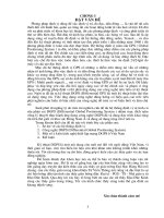
satellites are arranged so that four satellites are placed in each of six orbital
planes (Figure 1.1). With this constellation geometry, four to ten GPS satellites will be visible anywhere in the world, if an elevation angle of 10° is
considered. As discussed later, only four satellites are needed to provide the
positioning, or location, information.
GPS satellite orbits are nearly circular (an elliptical shape with a maximum eccentricity is about 0.01), with an inclination of about 55° to the
equator. The semimajor axis of a GPS orbit is about 26,560 km (i.e., the satellite altitude of about 20,200 km above the Earths surface) [4]. The corresponding GPS orbital period is about 12 sidereal hours (~11 hours, 58
minutes). The GPS system was officially declared to have achieved full
operational capability (FOC) on July 17, 1995, ensuring the availability of
at least 24 operational, nonexperimental, GPS satellites. In fact, as shown in
Section 1.4, since GPS achieved its FOC, the number of satellites in the GPS
constellation has always been more than 24 operational satellites.
1.2 GPS segments
GPS consists of three segments: the space segment, the control segment,
and the user segment (Figure 1.2) [5]. The space segment consists of the
24-satellite constellation introduced in the previous section. Each GPS satellite transmits a signal, which has a number of components: two sine
waves (also known as carrier frequencies), two digital codes, and a navigation message. The codes and the navigation message are added to the carriers as binary biphase modulations [5]. The carriers and the codes are used
mainly to determine the distance from the users receiver to the GPS
Solar panel
L-band antenna
S-band antenna
Figure 1.1 GPS constellation.
Introduction to GPS
3
Space
segment
GPS
signal
Download
(L-band)
Control segment
AM
FL
Y
Upload
(S-band)
User segment
Figure 1.2 GPS segments.
TE
satellites. The navigation message contains, along with other information, the coordinates (the location) of the satellites as a function of
time. The transmitted signals are controlled by highly accurate atomic
clocks onboard the satellites. More about the GPS signal is given in
Chapter 2.
The control segment of the GPS system consists of a worldwide network of tracking stations, with a master control station (MCS) located in
the United States at Colorado Springs, Colorado. The primary task of the
operational control segment is tracking the GPS satellites in order to determine and predict satellite locations, system integrity, behavior of the satellite atomic clocks, atmospheric data, the satellite almanac, and other
considerations. This information is then packed and uploaded into the
GPS satellites through the S-band link.
The user segment includes all military and civilian users. With a GPS
receiver connected to a GPS antenna, a user can receive the GPS signals,
which can be used to determine his or her position anywhere in the world.
GPS is currently available to all users worldwide at no direct charge.
4
Introduction to GPS
1.3 GPS satellite generations
GPS satellite constellation buildup started with a series of 11 satellites
known as Block I satellites (Figure 1.3). The first satellite in this series (and
in the GPS system) was launched on February 22, 1978; the last was
launched on October 9, 1985. Block I satellites were built mainly for experimental purposes. The inclination angle of the orbital planes of these
satellites, with respect to the equator, was 63°, which was modified in
the following satellite generations [6]. Although the design lifetime of
Block I satellites was 4.5 years, some remained in service for more than
10 years. The last Block I satellite was taken out of service on November 18,
1995.
The second generation of the GPS satellites is known as Block II/IIA
satellites (Figure 1.3). Block IIA is an advanced version of Block II, with an
increase in the navigation message data storage capability from 14 days for
Block II to 180 days for Block IIA. This means that Block II and Block IIA
satellites can function continuously, without ground support, for periods
of 14 and 180 days, respectively. A total of 28 Block II/IIA satellites were
launched during the period from February 1989 to November 1997. Of
these, 23 are currently in service. Unlike Block I, the orbital plane of Block
II/IIA satellites are inclined by 55° with respect to the equator. The design
lifetime of a Block II/IIA satellite is 7.5 years, which was exceeded by most
Block II/IIA satellites. To ensure national security, some security features,
known as selective availability (SA) and antispoofing, were added to Block
II/IIA satellites [3, 6].
A new generation of GPS satellites, known as Block IIR, is currently
being launched (Figure 1.3). These replenishment satellites will be backward compatible with Block II/IIA, which means that the changes are
transparent to the users. Block IIR consists of 21 satellites with a design life
of 10 years. In addition to the expected higher accuracy, Block IIR satellites
have the capability of operating autonomously for at least 180 days without
ground corrections or accuracy degradation. The autonomous navigation
capability of this satellite generation is achieved in part through mutual
satellite ranging capabilities. In addition, predicted ephemeris and clock
data for a period of 210 days are uploaded by the ground control segment
to support the autonomous navigation. More features will be added to the
last 12 Block IIR satellites under the GPS modernization program, which
will be launched at the beginning of 2003 [7]. As of July 2001, six Block IIR
satellites have been successfully launched.
Introduction to GPS
Block I
Block II/IIA
5
Block IIR
Figure 1.3 GPS satellite generations. (From http:\\www2.geod.hrcan.gc.ca/
~craymer/gps.html.)
Block IIR will be followed by another system, called Block IIF (for
follow-on), consisting of 33 satellites. The satellite life span will be 15
years. Block IIF satellites will have new capabilities under the GPS modernization program that will dramatically improve the autonomous GPS
positioning accuracy (see Chapter 2 for details). The first Block IIF satellite
is scheduled to be launched in 2005 or shortly after that date.
1.4 Current GPS satellite constellation
The current GPS constellation (as of July 2001) contains five Block II, 18
Block IIA, and six Block IIR satellites (see Table 1.1). This makes the total
number of GPS satellites in the constellation to be 29, which exceeds the
nominal 24-satellite constellation by five satellites [8]. All Block I satellites
are no longer operational.
The GPS satellites are placed in six orbital planes, which are labeled A
through F. Since more satellites are currently available than the nominal
24-satellite constellation, an orbital plane may contain four or five satellites. As shown in Table 1.1, all of the orbital planes have five satellites,
except for orbital plane C, which has only four. The satellites can be identified by various systems. The most popular identification systems within the
GPS user community are the space vehicle number (SVN) and the pseudorandom noise (PRN); the PRN number will be defined later. Block
II/IIA satellites are equipped with four onboard atomic clocks: two cesium
(Cs) and two rubidium (Rb). The cesium clock is used as the primary timing source to control the GPS signal. Block IIR satellites, however, use
6
Introduction to GPS
Table 1.1
GPS Satellite Constellation as of July 2001
Sequence SVN
PRN
Orbital
Plane
Clock
Sequence
SVN
PRN
Orbital
Plane
Clock
II-2
13
2
B-3
Cs
II-21
39
9
A-1
II-4
19
19
A-5
Cs
II-22
35
5
B-4
Cs
II-5
17
17
D-3
Cs
II-23
34
4
D-4
Rb
II-8
21
21
E-2
Cs
II-24
36
6
C-1
Cs
II-9
15
15
D-5
Cs
II-25
33
3
C-2
Cs
II-10
23
23
E-5
Cs
II-26
40
10
E-3
Cs
II-11
24
24
D-1
Cs
II-27
30
30
B-2
Cs
II-12
25
25
A-2
Cs
II-28
38
8
A-3
Rb
II-14
26
26
F-2
Rb
IIR-2
43
13
F-3
Rb
Cs
II-15
27
27
A-4
Cs
IIR-3
46
11
D-2
Rb
II-16
32
1
F-4
Cs
IIR-4
51
20
E-1
Rb
II-17
29
29
F-5
Rb
IIR-5
44
28
B-5
Rb
II-18
22
22
B-1
Rb
IIR-6
41
14
F-1
Rb
II-19
31
31
C-3
Cs
IIR-7
54
18
E-4
Rb
II-20
37
7
C-4
Rb
rubidium clocks only. It should be pointed out that two satellites, PRN05
and PRN06, are equipped with corner cube reflectors to be tracked by laser
ranging (Table 1.1).
1.5 Control sites
The control segment of GPS consists of a master control station (MCS),
a worldwide network of monitor stations, and ground control stations
(Figure 1.4). The MCS, located near Colorado Springs, Colorado, is the
central processing facility of the control segment and is manned at all
times [9].
There are five monitor stations, located in Colorado Springs (with the
MCS), Hawaii, Kwajalein, Diego Garcia, and Ascension Island. The positions (or coordinates) of these monitor stations are known very precisely.
Introduction to GPS
7
Colorado Springs
Hawaii
Kwajalein
Cape
Canaveral
Ascension
Island
Diego Garcia
Master control station
Ground antenna
Monitor station
Backup ground antenna
Figure 1.4 GPS control sites.
Each monitor station is equipped with high-quality GPS receivers and a
cesium oscillator for the purpose of continuous tracking of all the GPS satellites in view. Three of the monitor stations (Kwajalein, Diego Garcia, and
Ascension Island) are also equipped with ground antennas for uploading
the information to the GPS satellites. All of the monitor stations and the
ground control stations are unmanned and operated remotely from the
MCS.
The GPS observations collected at the monitor stations are transmitted
to the MCS for processing. The outcome of the processing is predicted
satellite navigation data that includes, along with other information, the
satellite positions as a function of time, the satellite clock parameters,
atmospheric data, satellite almanac, and others. This fresh navigation data
is sent to one of the ground control stations to upload it to the GPS satellites through the S-band link.