AN0729 LIN protocol implementation using PICmicro® MCUs
Bạn đang xem bản rút gọn của tài liệu. Xem và tải ngay bản đầy đủ của tài liệu tại đây (144.66 KB, 35 trang )
AN729
LIN Protocol Implementation Using PICmicro® MCUs
Authors:
ever, instead of having a clock line, each byte is marked
via start and stop bits and the individual bits are asynchronously timed like RS232.
Dan Butler
Thomas Schmidt
Thorsten Waclawczyk
Microchip Technology Inc.
ELECTRICAL CONNECTIONS
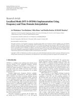
Figure 1 shows a typical LIN Protocol configuration.
INTRODUCTION
LIN Protocol was designed by a consortium of European auto manufacturers as a low cost, short distance,
low speed network. Designed to communicate changes
in switch settings and respond to switch changes, it is
intended to communicate events that happen in
"human" time (hundreds of milliseconds).
This Application Note is not intended to replace or
recreate the LIN Protocol Specification. Rather, it is
intended to provide a broad overview of the bus and
provide a high level look at how it works, how to implement a Slave node on a PICmicro® device and what it’s
designed to do. The complete LIN Protocol Specification is expected to be available via the worldwide web
at www.lin-subbus.com. However, until then, copies of
the LIN Protocol Specification may only be distributed
by Audi AG, BMW AG, DaimlerChrysler AG, Motorola,
Inc., Volcano Communication Technologies AB, Volkswagen AG, and Volvo Car Corporation.
The bus uses a single wire pulled high through a resistor with open collector drivers. A Dominant state is signaled by a ground level on the bus and occurs when
any node pulls the bus low. A Recessive state is when
the bus is at VBAT (9 - 18V) and requires that all nodes
let the bus float. In the idle state, the bus floats high,
pulled up through the resistor.
The bus operates between 9V and 18V, but parts must
survive 40V on the bus. Typically, the microcontroller is
isolated from the bus levels by a line driver/receiver.
This allows the microcontrollers to operate at 5V levels,
while the bus operates at higher levels.
The bus is terminated to VBAT at each node. The Master is terminated through a 1KΩ resistor, while the
Slaves are terminated through a 20-47KΩ resistor.
Maximum bus length is designed to be 40 meters.
At press time (early 2000), K-Line drivers are used until
true LIN drivers are available.
BUS FEATURES
LIN Protocol supports bi-directional communication on
a single wire, while using inexpensive microcontrollers
driven by RC oscillators, to avoid the cost of crystals or
ceramic resonators. Instead of paying the price for
accurate hardware, it pays the price in time and software. The protocol includes an autobaud step on every
message. Transfer rates of up to 20Kbaud are supported, along with a low power SLEEP mode, where
the bus is shut down to prevent draining the battery, but
the bus can be powered up by any node on the bus.
The bus itself is a cross between I2CTM and RS232.
The bus is pulled high via a resistor and each node
pulls it low, via an open collector driver like I2C. How-
2000 Microchip Technology Inc.
Preliminary
DS00729A-page 1
AN729
FIGURE 1:
BUS CONFIGURATION
40m
MaxiLIN Protocol
30KΩ nom
1KΩ
30KΩ nom
VBAT
VBAT
30KΩ nom
VBAT
VBAT
LIN
Transceiver
LIN
Transceiver
LIN
Transceiver
LIN
Transceiver
Master
µC
Slave 1
µC
Slave 2
µC
Slave n <16
µC
BYTE PROTOCOL
Each byte is framed by start and stop bits as shown in
Figure 2. Within each byte, data is transmitted LSb first.
The start bit is the opposite of the idle state or zero, and
the stop bit equals the idle state (1).
FIGURE 2:
BYTE PROTOCOL
bit 0
Bus Idle
Start
bit
1
2
3
4
LSb
5
6
7
MSb
Stop
bit
Each byte is framed by a start bit and stop bit, and data is transmitted Least Significant bit first.
DS00729A-page 2
Preliminary
2000 Microchip Technology Inc.
AN729
MESSAGE PROTOCOL
The Master controls the bus by polling Slaves to share
their data with the rest of the bus. Slave nodes only
transmit when commanded by the Master, which allows
bi-directional communication without further arbitration.
Message transfers start with the Master issuing a
synch break, followed by a synch field and a message
field. It also sets the clock for the entire bus by transmitting a synch field at the beginning of each message,
which is used for clock synchronization. Each Slave
must use this synch byte to adjust their baud rate.
The synch break is bus dominant, held for 13 bit times,
followed by a stop bit (recessive). This lets the Slaves
know that a message is coming. The Master and Slave
FIGURE 3:
clocks may have drifted as much as 15%. Therefore,
the synch break may be received by a Slave as only 11
bit times, or as long as 15 bit times.
The second byte of each message is an ident byte,
which tells the bus what data will follow and indicates
which node should answer and how long the answer
shall be. Only one Slave may respond to a given
command.
Slaves only transmit data on the bus when directed by
the Master. Once the data is on the bus, any node may
receive that data. Therefore, communication from one
Slave to another does not have to be directed through
the Master.
MESSAGE PROTOCOL
Message
Header
Bus Idle
Synch
Break
Synch
Field
Response
Ident
Field
Data
Byte 1
Data
Byte 2
Data
Byte 3
Checksum
Interframe Response Space
2000 Microchip Technology Inc.
Preliminary
DS00729A-page 3
AN729
CLOCK SYNCHRONIZATION
IDENTIFIER FIELD
LIN Protocol is designed to use low cost RC oscillators
on the controllers. To keep communication working as
each node’s clock drifts, Slaves must detect the Master’s baud rate on every transfer and adjust to the current baud rate. For this reason, each transaction starts
with a synch field. The synch field is a one byte 0x55
(alternating 0’s and 1’s). This allows every Slave node
to detect 8 bit times. By counting these transitions,
dividing by 8 and rounding, each Slave adjusts their
timing to the Master.
Following the synch field, is an identifier field, which
tells the bus what’s coming next. The ident field is broken up into 3 fields: 4 bits (0-3) address devices on the
bus, 2 bits (4-5) indicate the length of the message to
follow and the last 2 bits (6-7) are used for parity.
The 4 address bits can address up to 16 Slaves, and
each Slave can send a 2, 4 or 8 byte response, for a
total of 64 different messages.
The LIN Protocol Specification does not define the content of each message, except for the SLEEP command
detailed in the Lower Power Sleep section. Instead, that
is left up to the application.
Messages from one node to another may be sent
directly, as directed by the Master. The data does not
have to be received by the Master and retransmitted to
the receiving node. Instead, any message may be
received and acted upon by any node.
FIGURE 4:
SYNCH FIELD
Start
bit
Bus Idle
Start
Clock
0
1
LSb
1
1
0
2
1
0
3
1
0
MSb
Stop
bit
4
Count time for 4 successive falling edges, then divide by 8 and round, to get a single bit time. The divide
and round is easily implemented as 3 right shifts and add the carry back in.
DS00729A-page 4
Preliminary
2000 Microchip Technology Inc.
AN729
FIGURE 5:
IDENT FIELD
P1
P0
ID5
ID4
P0:
Parity bit
ID0 ⊕ ID1 ⊕ ID2 ⊕ ID4
P1:
Parity bit
ID1 ⊕ ID3 ⊕ ID4 ⊕ ID5
ID0 - 3:
Device Address
ID4 - 5:
Message Length
ID3
ID5
ID4
Date Bytes
0
0
1
1
0
1
0
1
2
2
4
8
2000 Microchip Technology Inc.
Preliminary
ID2
ID1
ID0
DS00729A-page 5
AN729
ERROR DETECTION
LIN Protocol is not directly compatible to CANBUS,
however, it is anticipated that the two will operate in
conjunction with one another. CANBUS might be used
for communication throughout the car, while LIN Protocol would only be used within a small section of the car,
say within the door.
The following errors must be detected and counted
within each node:
• Bit Errors: The transmitting node should compare
what it thinks should be on the bus against what
actually is on the bus. The controllers must wait
long enough for the bus to respond before testing
for the bit. Given the minimum edge slew rates
are 1V/uS, and the maximum bus voltage (18V),
the transmitter should wait 18µS before testing, to
see if the bit on the bus is correct.
• Checksum Errors: The data content of each message is protected by a checksum byte, which is
the inverted module-256 checksum of the data
bytes.
• Parity Errors: The command byte uses 2 parity
bits to protect the other 6. These need to be
recalculated and compared.
A CAN-LIN Protocol interface node would be necessary to connect the two busses. The interface node
would collect information from the LIN Protocol nodes
and pass that information along on CANBUS.
LOWER POWER SLEEP
The Master may direct all nodes to enter a SLEEP
mode by sending a ident code of 0x80. This is the only
message ID defined in the LIN Protocol Specification.
The content of the data bytes following the SLEEP
command is not defined. Slaves receiving the SLEEP
command should set-up for a wake-up on change from
the bus and power-down to minimum current drain. The
bus will float high and not consume current.
If there is an error, the command should be ignored and
the error logged.
Any node may wake-up the bus by sending a wake-up
signal, which is a character 0x80 (low for 7 bit times followed by 1 bit time high). When this signal is received,
all nodes should wake-up and wait for the Master to
start polling the bus in the normal fashion.
ERROR REPORTING
There is no direct error reporting mechanism. However,
each Slave node is expected to track it’s own errors.
The Master may then request error status as part of a
normal message protocol.
If the Master fails to wake up after 128 bit times
(6400uS @ 20Kbaud), the node that is attempting to
wake the Master should try again. This may be
attempted a total of 3 times before waiting 15000 bit
times (750mS @ 20Kbaud).
CANBUS INTERFACE
FIGURE 6:
SLEEP MESSAGE
SLEEP Mode Frame
Sync
Break
DS00729A-page 6
Sync
Field
SLEEP
0x80
Data
1
Data
2
Preliminary
Checksum
Any Slave
Master
Wake-up
0x80
Synch
Break
2000 Microchip Technology Inc.
AN729
DEMONSTRATION SOFTWARE
SOFTWARE FUNCTION
The code in Appendix A demonstrates communication
on the LIN Protocol. The hardware consists of 2 buttons
and 3 LEDs, as shown in Figure 7. LED #1 changes
state for every 10 button pushes of button #1. Likewise,
LED #2 changes state for every 10 presses of button
#2. In response to ID 1, the button counts are transmitted on the bus. In response to ID 4, the button counts
are updated from the bus.
In order to initialize the LIN Protocol Slave handler, the
user has to call the routine InitLinSlave. This routine initializes the RB0 interrupt pin and the TMR0.
TMR0 will be used to measure the bit length and to
generate the baudrate. After initialization, the user can
execute his code. The code will be interrupted once a
falling edge is detected on RB0. If a falling edge is
detected, the code will branch into the interrupt service
routine. All interrupts, except for TMR0 and RB0, must
be disabled to accurately time the synch field. After the
baudrate is calculated, the interrupt service routine is
exited. Upon the next interrupt on RB0, the LIN Protocol Slavehandler goes automatically into receive mode
in order to receive the identifier field or data bytes.
Once the start bit of the identifier field or data byte is
detected, where the program branches into the interrupt service routine, the identifier field is received and
decoded. Depending on the received identifier, code is
executed, for example, storing data, turn on LED, etc.
This code has to be included by the user into the subroutine DecodeIdTable after the routine is executed.
FIGURE 7:
DEMONSTRATION HARDWARE
LIN Protocol
30K nom
VBAT
PICmicro® MCU
B0
B4
B1
B2
B5
B6
LIN Protocol
Driver
B7
After the bus frame is completed, the flag FCOMPLETE
is set. This flag indicates that all data is received correctly and ready for further processing. This flag has to
be cleared by the user’s firmware.
Note:
TMR0 is used for bit time measurement and
baudrate generation. Therefore, TMR0 is
not available to application software.
SOFTWARE OPERATION
The LIN Protocol code works on the interrupt as triggered from RB0. This is necessary to implement the
SLEEP/Wake- up requirement. Once the interrupt is
triggered, it counts the length of the low bit time. Then
the synch byte is read and the local bit time is determined. This is then compared against the original bit
time to determine if the original low time was more than
10 bit times and thus, signaled a synch break, or less
than 10, signaling a wake up from SLEEP.
If it’s a wake up from SLEEP, the code exits and continues waiting for a synch break.
If it’s a synch break, it then reads in the command byte,
checks the parity bits and checks the action table to
determine it’s actions from there. The action table
defines the source or destination for the data on the
bus.
2000 Microchip Technology Inc.
Preliminary
DS00729A-page 7
AN729
ERROR DETECTION
When the Slave code detects an error, it’s recorded in
the ERRORFLAGS register as shown in figure 8, and the
message is ignored. These error flags are cleared
once a valid ident field is received.
The Slave node process detects the following errors:
•
•
•
•
•
Checksum error
Bit errors
Missing Stop bit
Parity error
Time-out errors
FIGURE 8:
ERROR FLAGS
7
Time
Out
6...
4
Not
Used
3
2
1
0
Bit
Error
CRC
Error
ID Parity
Error
No
Response
These flags are set when detected.
SOFTWARE PERFORMANCE
INTEGRATION INTO CUSTOM CODE
The LIN Protocol Slavehandler can operate up to a
speed of 20Kbaud.
The user has to edit the subroutine DecodeIDTable.
In this section, the user defines what action has to be
taken upon a certain identifier. Furthermore, the user
can define what action has to be taken upon certain
errors, (i.e., timing error or others).
The LIN Protocol Slavehandler requires 420 words of
program memory (not including program memory for
macros for the In Out IDs) and 23 bytes of data memory.
This application is ideal for Microchip’s internal RC
oscillator operating at 4MHz.
DS00729A-page 8
Preliminary
2000 Microchip Technology Inc.
2000 Microchip Technology Inc.
Software License Agreement
The software supplied herewith by Microchip Technology Incorporated (the “Company”) for its PICmicro® Microcontroller is
intended and supplied to you, the Company’s customer, for use solely and exclusively on Microchip PICmicro Microcontroller products.
The software is owned by the Company and/or its supplier, and is protected under applicable copyright laws. All rights are reserved.
Any use in violation of the foregoing restrictions may subject the user to criminal sanctions under applicable laws, as well as to civil
liability for the breach of the terms and conditions of this license.
THIS SOFTWARE IS PROVIDED IN AN “AS IS” CONDITION. NO WARRANTIES, WHETHER EXPRESS, IMPLIED OR STATUTORY, INCLUDING, BUT NOT LIMITED TO, IMPLIED WARRANTIES OF MERCHANTABILITY AND FITNESS FOR A PARTICULAR PURPOSE APPLY TO THIS SOFTWARE. THE COMPANY SHALL NOT, IN ANY CIRCUMSTANCES, BE LIABLE FOR
SPECIAL, INCIDENTAL OR CONSEQUENTIAL DAMAGES, FOR ANY REASON WHATSOEVER.
APPENDIX A: SOURCE CODE
Preliminary
MPASM 02.30.09 Intermediate
LOC OBJECT CODE
VALUE
LINSLAVE.ASM
1-27-2000
9:57:59
PAGE
1
LINE SOURCE TEXT
;
;
;
;
;
;
;
;
;
;
;
;
;
;
;
;
;
;
;
;
;
Software License Agreement
The software supplied herewith by Microchip Technology Incorporated (the "Company")
for its PICmicro® Microcontroller is intended and supplied to you, the Company’s
customer, for use solely and exclusively on Microchip PICmicro Microcontroller
products.
The software is owned by the Company and/or its supplier, and is protected under
applicable copyright laws. All rights are reserved. Any use in violation of the
foregoing restrictions may subject the user to criminal sanctions under applicable
laws, as well as to civil liability for the breach of the terms and conditions of
this license.
THIS SOFTWARE IS PROVIDED IN AN "AS IS" CONDITION. NO WARRANTIES, WHETHER EXPRESS,
IMPLIED OR STATUTORY, INCLUDING, BUT NOT LIMITED TO, IMPLIED WARRANTIES OF
MERCHANTABILITY AND FITNESS FOR A PARTICULAR PURPOSE APPLY TO THIS SOFTWARE. THE
COMPANY SHALL NOT, IN ANY CIRCUMSTANCES, BE LIABLE FOR SPECIAL, INCIDENTAL OR
CONSEQUENTIAL DAMAGES, FOR ANY REASON WHATSOEVER.
###############################################################################
filename:
LINSLAVE.ASM
AN729
DS00729A-page 9
00001
00002
00003
00004
00005
00006
00007
00008
00009
00010
00011
00012
00013
00014
00015
00016
00017
00018
00019
00020
00021
00022
00023
00024
00025
00026
00027
00028
00029
00030
00031
00032
00033
00034
00035
00036
00037
00038
00039
00040
00041
00042
00043
00044
00045
00046
00047
00048
00049
00050
00051
00052
00053
00054
00055
00056
00057
00058
00059
00060
00061
00062
00063
00064
00065
00066
00067
00068
;
LIN ( Local Interconnect Network ) SpecRev 1.0
;
; ###############################################################################
;
;
Author:
Thorsten Waclawczyk
;
Company:
Arizona Microchip Technology GmbH
;
;
Revision:
1.7
;
Date:
18-JAN-2000
;
Assembled using
MPASM 2.30.07
;
;################################################################################
;
;
include files:
;
p16C622.inc
Rev 1.01
;
;################################################################################
;
;
Implements the LIN slave handler conforming the LIN spec revision 1.0 with
;
using the external interupt INTE and TMR0 as an interrupt based system.
;
;
LIN HANDLER DESCRIPTION
;
;
The linslave handler must be initialized before starting the main task
;
by calling the routine "InitLinSlave".
;
;
After initialization the interrupt based LIN handler waits on first falling
;
and a second rising edge to measure the length of synchbreak lowtime.
;
Then the LIN handler waits for the next falling edge to count the processor
;
cycles between the next four falling edge detections.
;
;
This result is divided by 8 to get the bitlength. To make sure that
;
this is the header sequence, the bitlength is multiplied by 10 and
;
compared to the initial synchbreak count. If the synchbreak count is
;
longer, we know it was a synchbreak.
;
;
After that the LIN handler is set in receive mode to read the identifier
;
by using the bitlength value set into the timer0.
;
When the byte has received it will be checked and decoded in the subroutine
;
"CheckIdentifierByte" so that the LIN handler can handle the incoming or
;
outgoing resonse frame.
;
;
The timing and error checking will be handled by the LIN handler so that
;
the only thing the user has to do is define the DecodeIdTable.
;
This gives an action to each of the 16 possible IDs that may come across
;
from the master. Three actions are possible:
MacroLstMode, listen but
;
take no action on the data. MacroRsMode, which provides a buffer for
AN729
DS00729A-page 10
Preliminary
2000 Microchip Technology Inc.
2007
3FFB
00069
00070
00071
00072
00073
00074
00075
00076
00077
00078
00079
00080
00081
00082
00083
00084
00085
00086
00087
00088
00089
00090
00091
00092
00093
00094
00095
00096
00097
00098
00099
00100
00101
00102
00103
00104
00105
00106
00107
00001
00002
00165
00108
00109
00110
00111
00112
2000 Microchip Technology Inc.
Preliminary
_CP_OFF & _WDT_OFF & _RC_OSC
Microchip Technology, Inc.
; #### defines ##################################################################
__CONFIG
#include
LIST
; P16C622.INC Standard Header File, Version 1.01
LIST
LIST p=16C622,F=INHX8M
;
recieving data. MacroTxMode while sets up a buffer to transmit from.
;
;
When a complete message frame has been done a flag "COMFLAGS,FCOMPLETE"
;
is set. So after that the user can process the data in the buffer
;
if there are no errors. After data is processed the complete flag must
;
be cleared by the user to signal that the data has been processed.
;
;
DEMO PROGRAM DESCRIPTION
;
;
The slave node has two buttons and three LEDs. The buttons are read in
;
and counted. The button counts are transmitted in response to ID1.
;
;
LEDs 1 and 2 change state when the value of the register corresponding
;
counter (COMPLED1 or COMPLED2) matches the delimiter value, currently
;
set to 10.
;
;
ID4 updates the counters via the LIN bus.
;
;
LED3 toggles each time it detects a complete message frame.
;
; ###############################################################################
;
;
what’s changed
;
;
changes
date of changes
;
;
; ###############################################################################
;
;
program and data usage
;
program
:
0x0420
;
data
:
0x24
;
stacklevel
:
2
;
; ###############################################################################
AN729
DS00729A-page 11
DS00729A-page 12
Preliminary
000000A0
00000027
00000029
0000002B
0000002C
0000002D
0000002E
0000002F
00000030
00000031
00000032
00000033
0000003B
00000043
00000024
00000025
00000022
00000020
00000021
00113
00114
00115
00116
00117
00118
00119
00120
00121
00122
00123
00124
00125
00126
00127
00128
00129
00130
00131
00132
00133
00134
00135
00136
00137
00138
00139
00140
00141
00142
00143
00144
00145
00146
00147
00148
00149
00150
00151
00152
00153
00154
00155
00156
00157
00158
00159
0x20
#define LINSLAVERAM
; startadress
; PB0 connected to the receive line
; PB4 connected to the send line
EQU
(COPYWREG + 80h)
bitposition and bitlength
numbers of send/receive block
carries the id field bits5..0
carries the ID_number
protocols communication errors
linbus communication bits
; reserve RAM location on page1
; checksum over xmit / rcsv block
; data transmission buffer
; data receive block buffer
;
;
;
;
;
;
; temporary highbyte for TMR0
; and timeout counter
;
; software counter for baudrate
; holds a copy of WREG
; holds a copy of STATUS
7
3
2
1
#define FTIMEOUT
#define FBITERROR
#define FCRCERROR
#define FIDPARITYERROR
; #### bit defines #
; defines for the errorflag variable
;
;
;
;
;
no communication on receive / transmit
an outgoing bit value is
different than the line value
CRC isn’t correct
parity over ID not correct
#define LINSLAVEBLOCKLENGTH (DUMMY+1 - LINSLAVERAM)
#define LINBLOCKEND
(DUMMY+1)
;#############################################################
;
; calculate the needed RAM
; space by LINslave
MIRRCOPYWREG
SYNCLENGTH:0,SYNCLENGTHLO,SYNCLENGTHHI
BITREG:0,BITNBR,BITLENGTH
DATABLOCKLENGTH
PREIDNUMBER
IDNUMBER
ERRORFLAGS
COMFLAGS
BUFFERPTR
COMBUFFER
DATACRC
TXDATAFIELD:8
RSDATAFIELD:8
DUMMY:2
ENDC
COUNTEDGES
COUNTVALUE:0,COUNTVALUELO,COUNTVALUEHI
HICOUNT:0,TIMEOUTLO,TIMEOUTHI
CBLOCK LINSLAVERAM
COPYWREG
COPYSTATUS
; ---- RAM location used by LINSLAVE modul --------------------------------------
0
4
#define RSLINEPIN
#define TXLINEPIN
AN729
2000 Microchip Technology Inc.
2000 Microchip Technology Inc.
Preliminary
00000047
00000048
00000049
00000046
00000045
0000003B
0000003C
00000033
00000034
00203
00204
00205
00160
00161
00162
00163
00164
00165
00166
00167
00168
00169
00170
00171
00172
00173
00174
00175
00176
00177
00178
00179
00180
00181
00182
00183
00184
00185
00186
00187
00188
00189
00190
00191
00192
00193
00194
00195
00196
00197
00198
00199
00200
00201
00202
0
FSYNCHBREAK
FID
FRSDATA
FTXDATA
FCOMDATA
FLISTENONLY
FCOMPLETE
FSLEEPMODE
0
1
2
3
4
5
6
7
;
;
;
;
;
;
;
;
synch_break detected
ID byte receives as next byte
data block read
data block to be sent
communication is running
ID byte is a command only for
communication completed
sleep-mode frame
; no echo on bus
B2FILTER
DEBOUNCECOUNTER
COPYPORTB
B1FILTER
CBLOCK LINBLOCKEND+1
COMPERATOR
; define global variables used by the main task
; debouncefilter button2
; contains the delimiter to
; switch on/off the LEDs
; debouncefilter button1
; register used by ID4
;
CBLOCK RSDATAFIELD
COMPLED1
COMPLED2
ENDC
; input
; register used by ID1
;
1
2
#define BUTTON1
#define BUTTON2
; Toggles after 10 presses of button 1
; toggles after 10 presses of button 2
; indicates complete message frame
CBLOCK TXDATAFIELD
BUTTONPRESSED1
BUTTONPRESSED2
ENDC
5
6
7
#define LED1
#define LED2
#define LED3
; ###############################################################################
; #### main task declaration ####################################################
;
;
at this point used variables for the demo program will be defined
;
#define
#define
#define
#define
#define
#define
#define
#define
; defines for the comflag variable
#define FNORESPONSE
AN729
DS00729A-page 13
DS00729A-page 14
Preliminary
0004
0004
0005
0006
0007
0008
0008
0000
0000
1D0B
00A0
0803
1283
00A1
29A9
0000004A
00206
00207
00208
00209
00210
00211
00212
00213
00214
00215
00216
00217
00218
00219
00220
00221
00222
00223
00224
00225
00226
00227
00228
00229
00230
00231
00232
00233
00234
00235
00236
00237
00238
00239
00240
00241
00242
00243
00244
00245
00246
00247
00248
00249
00250
00251
00252
BUFFERPTR
0
BUFFERPTR
0
0
;
;
;
;
;
;
;
;
;
;
;
;
indicates the receive mode
without saving the received data
this is necessary to have
a correct jump table length
indicates the transmission mode
get the wanted ram location
where the data will read from
and initialize the pointer
indicates the receive mode
get the wanted ram location
where the data will stored
and initialize the pointer
goto
Main
org
0x0000
; reset-vector
INTvector
movwf
movf
bcf
movwf
TMR0int
btfss
INTCON,T0IF
org
0x0004
COPYWREG
STATUS,W
STATUS,RP0
COPYSTATUS
; save the used registers WREG
;
; switch to bank0
; save STATUS in page0
; #### INTvector ################################################################
RESET
; #### RESETvector ##############################################################
nop
nop
retlw
ENDM
MacroLstMode MACRO
bsf
COMFLAGS,FLISTENONLY
movwf
retlw
ENDM
MacroTxMode MACRO
StartAddrOfPtr
bsf
COMFLAGS,FTXDATA
movlw
StartAddrOfPtr
movwf
retlw
ENDM
MacroRsMode MACRO
StartAddrOfPtr
bsf
COMFLAGS,FRSDATA
movlw
StartAddrOfPtr
; #### declare MODE macros ######################################################
; ###############################################################################
;################################################################################
EDGEDETECT
ENDC
AN729
2000 Microchip Technology Inc.
2815
00253
goto
ExtInt
; if timer int enabled
00254
000A
0AA2
00255
incf
HICOUNT,F
; increment highbyte is also
000B
1D03
00256
btfss
STATUS,Z
; the lowbyte of timeout counter
000C
2810
00257
goto
TMR0Int1
00258
000D
0AA3
00259
incf
TIMEOUTHI,F
; timeout sequence after
000E
19A3
00260
btfsc
TIMEOUTHI,3
; 3000 * 256 cycles
000F
17AE
00261
bsf
ERRORFLAGS,FTIMEOUT
; signal the timeout
00262
0010
00263 TMR0Int1
0010
110B
00264
bcf
INTCON,T0IF
; clear overflow flag
0011
192F
00265
btfsc
COMFLAGS,FRSDATA
; check if receiver mode
0012
2881
00266
goto
GetData
00267
0013
19AF
00268
btfsc
COMFLAGS,FTXDATA
; check if transmit mode
0014
28BE
00269
goto
PutData
00270
0015
00271 ExtInt
0015
1E0B
00272
btfss
INTCON,INTE
; check if external interupt
0016
28F8
00273
goto
IntrEnd
; is eanabled and
0017
1C8B
00274
btfss
INTCON,INTF
; possibly occured
0018
28F8
00275
goto
IntrEnd
00276
0019
3026
00277
movlw
0x26
; +12 cycles
001A
052F
00278
andwf
COMFLAGS,W
; if next byte is ID or falling
001B
1D03
00279
btfss
STATUS,Z
; edge of startbit initialize
001C
286D
00280
goto
GetDataInit
; reading a byte from bus
00281
001D
182F
00282
btfsc
COMFLAGS,FSYNCHBREAK
; was it a synch_break?
001E
2832
00283
goto
CountSynchByte
; yes : then the sequence to measure
00284
; the synch_byte will be expected
001F
1683
00285
bsf
STATUS,RP0
Message[302]: Register in operand not in bank 0. Ensure that bank bits are correct.
0020
1B01
00286
btfsc
OPTION_REG,INTEDG
; is rising edge selected
0021
2827
00287
goto
CopySyncBreakLength
; then save the count of synchbreak
Message[302]: Register in operand not in bank 0. Ensure that bank bits are correct.
0022
1701
00288
bsf
OPTION_REG,INTEDG
; else set rising edge sensitivity
0023
1283
00289
bcf
STATUS,RP0
00290
0024
0181
00291
clrf
TMR0
; initialize the used counter
0025
01A2
00292
clrf
HICOUNT
; to measure the synch break
0026
28F8
00293
goto
IntrEnd
; and now wait for rising edge int
00294
0027
00295 CopySyncBreakLength
Message[302]: Register in operand not in bank 0. Ensure that bank bits are correct.
0027
1301
00296
bcf
OPTION_REG,INTEDG
; set the falling edge sensitivity
0009
AN729
2000 Microchip Technology Inc.
Preliminary
DS00729A-page 15
DS00729A-page 16
0824
1D03
2837
0181
01A2
0032
0032
0033
0034
0035
0036
Preliminary
190B
0AA2
0801
00AA
1003
0CA2
0CAA
1003
0CA2
0CAA
1003
0CA2
0CAA
082A
3C31
1924
283B
0AA4
28F8
01A4
142F
28F8
002F
0030
0031
0037
0037
0038
0039
003A
003B
003B
003C
003D
003E
003F
0040
0041
0042
0043
0044
0045
0046
0047
0048
0049
1283
0801
00A7
0822
00A8
1903
2868
0028
0029
002A
002B
002C
002D
002E
00297
00298
00299
00300
00301
00302
00303
00304
00305
00306
00307
00308
00309
00310
00311
00312
00313
00314
00315
00316
00317
00318
00319
00320
00321
00322
00323
00324
00325
00326
00327
00328
00329
00330
00331
00332
00333
00334
00335
00336
00337
00338
00339
00340
00341
00342
00343
COUNTEDGES
COMFLAGS,FSYNCHBREAK
IntrEnd
STATUS,RP0
TMR0,W
SYNCLENGTH
HICOUNT,W
SYNCLENGTH+1
STATUS,Z
LowerSynchLength
;
;
;
;
;
;
if the hibyte is cleared the
received value was no synch break
sequence so start another
loop to detect a synch break
otherwise initialize the synch
byte detection and measurement
; to detect the startbit of
; the identifier byte
; save the counter value
CountSynchEdges
btfsc
goto
incf
goto
GetSynchLength
btfsc
incf
movf
movwf
bcf
rrf
rrf
bcf
rrf
rrf
bcf
rrf
rrf
movf
sublw
INTCON,T0IF
HICOUNT,F
TMR0,W
BITLENGTH
STATUS,C
HICOUNT,F
BITLENGTH,F
STATUS,C
HICOUNT,F
BITLENGTH,F
STATUS,C
HICOUNT,F
BITLENGTH,F
BITLENGTH,W
.49
COUNTEDGES,2
GetSynchLength
COUNTEDGES,F
IntrEnd
; result is in bitlength
;
; BITLENGTH lower than fastest
; dividing the 16Bit result by 8
; if all edges counted in
; calculate actual bitlength in
; cycle counts by
; wait for next falling edge
; else check count of passed edges
; ---- CountSynchByte ----------------------------------------------------------;
;
Counts the cycles between five falling edges to calculate single bitlength
;
for communicating with the master. The first falling edge clears the count
;
registers. After the fifth edge, the bitlength is calculated by dividing
;
the count by 8 and rounding.
;
CountSynchByte
; uses 17 cycles to arrive
movf
COUNTEDGES,W
btfss
STATUS,Z
; if first falling edge then
goto
CountSynchEdges
clrf
TMR0
;initialize bytelength couter
clrf
HICOUNT
clrf
bsf
goto
bcf
movf
movwf
movf
movwf
btfsc
goto
AN729
2000 Microchip Technology Inc.
2000 Microchip Technology Inc.
Preliminary
01C4
082A
00C3
1003
0DC3
0DC4
0DC3
0DC4
0DC3
0DC4
07C3
1803
0AC4
07C3
1803
0AC4
0844
0228
1C03
2868
1D03
286B
0843
0227
1C03
2868
1D03
286B
01AF
160B
28F8
004C
004C
004D
004E
004F
0050
0051
0052
0053
0054
0055
0056
0057
0058
0059
005A
005B
005C
005D
005E
005F
0060
0061
0062
0063
0064
0065
0066
0067
0068
0068
0069
006A
006B
1803
2868
004A
004B
00344
00345
00346
00347
00348
00349
00350
00351
00352
00353
00354
00355
00356
00357
00358
00359
00360
00361
00362
00363
00364
00365
00366
00367
00368
00369
00370
00371
00372
00373
00374
00375
00376
00377
00378
00379
00380
00381
00382
00383
00384
00385
00386
00387
00388
00389
00390
STATUS,C
LowerSynchLength
; bitrate
HigherSyncLength
LowerSynchLength
clrf
COMFLAGS
bsf
INTCON,INTE
goto
IntrEnd
CheckSynchBreakLength
clrf
DUMMY+1
movf
BITLENGTH,W
movwf
DUMMY
bcf
STATUS,C
rlf
DUMMY,F
rlf
DUMMY+1,F
rlf
DUMMY,F
rlf
DUMMY+1,F
rlf
DUMMY,F
rlf
DUMMY+1,F
addwf
DUMMY,F
btfsc
STATUS,C
incf
DUMMY+1,F
addwf
DUMMY,F
btfsc
STATUS,C
incf
DUMMY+1,F
movf
DUMMY+1,W
subwf
SYNCLENGTH+1,W
btfss
STATUS,C
goto
LowerSynchLength
btfss
STATUS,Z
goto
HigherSyncLength
movf
DUMMY,W
subwf
SYNCLENGTH,W
btfss
STATUS,C
goto
LowerSynchLength
btfss
STATUS,Z
goto
HigherSyncLength
first check the highbytes
bitlength *10 < synch length
yes -> no header detected
bitlength *10 = synch length
no -> header detected
highbytes are equal
check the lowbytes
; reset the linslave
; allow external interrupt
; to dedicate first faling edge
;
;
;
;
;
;
;
; and add bitlength value
; twice to multiply by 10
; multiply bitlengh with 8
;
; no -> do synch break length
; store bitlength
; ---- CheckSynchBreakLength ---------------------------------------------------;
;
Multiplies the counted bitlength by 10 to see if the synch break
;
is longer than a normal data byte. A normal data byte contains a dominant
;
startbit, 8 databits and a recessive stopbit, so if the measured lowtime
;
of the synchbreak is longer than 10 bitlength times it’s a synchbreak.
;
btfsc
goto
AN729
DS00729A-page 17
14AF
28F8
01B1
01A9
132F
082A
3CA6
1C03
2879
1003
0AA9
0C2A
072A
287A
0C2A
3AFF
3E3E
0081
3020
008B
152F
28F8
006B
006C
006D
006D
006E
006F
0070
0071
0072
0073
0074
0075
0076
0077
0078
0079
0079
007A
007A
007B
007C
007D
007E
007F
0080
00391
00392
00393
00394
00395
00396
00397
00398
00399
00400
00401
00402
00403
00404
00405
00406
00407
00408
00409
00410
00411
00412
00413
00414
00415
00416
00417
00418
00419
00420
00421
00422
00423
00424
00425
00426
00427
00428
00429
00430
00431
00432
00433
00434
00435
00436
00437
COMFLAGS,FID
IntrEnd
; next databyte comming in is the
; identifier byte
DS00729A-page 18
Preliminary
STATUS,C
BITNBR,F
BITLENGTH,W
BITLENGTH,W
GetDataInitEnd
BITLENGTH,W
.166
STATUS,C
SetHalfStartbitLength
COMBUFFER
BITNBR
COMFLAGS,FCOMPLETE
0xff
(.62)
TMR0
0x20
INTCON
COMFLAGS,FRSDATA
IntrEnd
clear input buffer
and the bit counter
clear communication complete
indicator
check if baudrate is less than
ca. 6 kBd
if higher then
set center position into startbit
; INTE off,T0IE on, clear flags
; set interrupts
; indicates receive mode
; build complement for timer
; correct timer to center stopbit
; center stopbit
; else center position into
; first databit by calculating
; one and a half bitlength
;
;
;
;
;
;
;
;
; ---- GetData ------------------------------------------------------------------
GetDataInitEnd
xorlw
addlw
movwf
movlw
movwf
bsf
goto
SetHalfStartbitLength
rrf
BITLENGTH,W
bcf
incf
rrf
addwf
goto
movf
sublw
btfss
goto
GetDataInit
clrf
clrf
bcf
; ---- GetDataInit -------------------------------------------------------------;
;
This function initializes the bitlength timer (TMR0) when the falling
;
edge of an start bit is detected so reading the bit takes place in the
;
center of the bit time.
;
;
For typical communication speeds 9600 to 19.2kbaud, we can set timer 0
;
to 1.5 bit times so we skip the remainder of the start bit and wake up
;
midway through the 1st data bit. However for slow baud rates, slower
;
than about 6 kbaud, 1.5 bit times may overflow the 8 bit timer. In
;
this case we set timer 0 to a half bit time so we’ll wake up mid way
;
through the start bit and adjust the bit counter to account for the
;
extra bit.
;
bsf
goto
AN729
2000 Microchip Technology Inc.
2000 Microchip Technology Inc.
Preliminary
3009
0629
1903
2891
1C06
1003
1806
1403
0CB1
0AA9
092A
0087
0088
0089
008A
008B
008C
008C
008D
01A2
01A3
0081
0081
0082
0083
0083
0084
0085
0086
00438
00439
00440
00441
00442
00443
00444
00445
00446
00447
00448
00449
00450
00451
00452
00453
00454
00455
00456
00457
00458
00459
00460
00461
00462
00463
00464
00465
00466
00467
00468
00469
00470
00471
00472
00473
00474
00475
00476
00477
00478
00479
00480
00481
00482
00483
00484
The received byte is a data byte of the response frame.
The data is stored in the receive buffer and the value is added
with the previous carry to build a modulo 256 checksum. The
last byte is the message checksum, which is compared with the
calculated checksum to check for message integrity.
2.
GetDataSetTMR
incf
comf
btfss
bcf
btfsc
bsf
rrf
BITNBR,F
BITLENGTH,W
PORTB,RSLINEPIN
STATUS,C
PORTB,RSLINEPIN
STATUS,C
COMBUFFER,F
; count received bit
; and center TMR0 to next bit
; shift carry into the buffer
; copy portvalue in data buffer
; using the Carryflag
; how many bits left
; stopbit received ?
; no : copy receive pin value
; delay of 13 cycles
; reset the timeout counter
The received byte is the identifier byte. At this point the
routine analyzes the byte to either set up the receive buffer,
transmit buffer or neither as designated by the function
"DecodeIDTable".
1.
We sample after TMR0 overflows, the routine copies the pin value into the
communication buffer and at checks the stopbit level to see if the data
is correct. After receiving all bits of a byte there are two possibilities.
If it was an identifier byte, we call DecodeIDTable to figure out what
to do next (Recieve message, transmit message or ignore message).
If it was a data byte, it is stored in the buffer previously set up by
the call to DecodeIDTable. When the all data has been received, the
checksum is calculated and compared against the transmitted value. If
there are no errors, the FCOMPLETE flag is set to signal that the
buffer should be processed.
Timer 0 has been set up to return here in time to test the incoming bit
midway through the bit time. This function samples the bit and rotates
the bit value into the data buffer.
clrf
TIMEOUTLO
clrf
TIMEOUTHI
CheckBitPosition
movlw
.9
xorwf
BITNBR,W
btfsc
STATUS,Z
goto
GetStopbit
GetData
;
;
;
;
;
;
;
;
;
;
;
;
;
;
;
;
;
;
;
;
;
;
;
;
;
;
;
;
AN729
DS00729A-page 19
DS00729A-page 20
Preliminary
082E
1D03
28A5
1AAF
28A5
0830
0084
0831
0080
07B2
1803
0AB2
0099
009A
009B
009C
009D
009E
009F
00A0
00A1
00A2
00A3
00A4
1AAF
28B7
032B
1903
28A7
03AB
0095
0096
0097
0098
00A7
00A7
00A8
18AF
28AF
0093
0094
0AB0
28B0
1C06
15AE
0091
0091
0092
00A5
00A5
00A6
3E1F
0081
28BD
008E
008F
0090
00485
00486
00487
00488
00489
00490
00491
00492
00493
00494
00495
00496
00497
00498
00499
00500
00501
00502
00503
00504
00505
00506
00507
00508
00509
00510
00511
00512
00513
00514
00515
00516
00517
00518
00519
00520
00521
00522
00523
00524
00525
00526
00527
00528
00529
00530
00531
BUFFERPTR,W
FSR
COMBUFFER,W
INDF
COMFLAGS,FLISTENONLY
SetNextLoc
ERRORFLAGS,W
STATUS,Z
SetNextLoc
DATABLOCKLENGTH,W
STATUS,Z
GetCheckCRC
DATABLOCKLENGTH,F
COMFLAGS,FID
GetAction
PORTB,RSLINEPIN
ERRORFLAGS,FBITERROR
(.31)
TMR0
GetDataEnd
if identifier byte is received
check this byte to initialize
the commanded slave mode
else if all bytes came in
;
;
;
;
get pointer
and point to location
catch the actual data
and ship it into the block
; or if slave monitors line
; ignore the next steps
; check if there are no errors
; if an error has detected
; don’t store the value
; the last byte is the Checksum
; else wait for the next byte
;
;
;
;
; check polarity of stopbit
; if low level set error flag
; with the correct value
addwf
btfsc
incf
COMFLAGS,FLISTENONLY
GetDataFinish
; ignore checksum calculation
; if slave reads only messages
; point to next location
; add new data into CRC
; add carry if mod 256
; produces an overflow
;
; generate sum of inverted mod 256 over data block plus CRC is 0xFF
; calculate 0xFF - SUM[RSDATAFIELD] = received CRC
GetCheckCRC
btfsc
goto
BUFFERPTR,F
InitGetData
DATACRC,F
STATUS,C
DATACRC,F
caluclate the checksum over received data bytes with MOD256
DATACRC = DATACRC + COMBUFFER + Carry
SetNextLoc
incf
goto
;
;
;
;
movf
movwf
movf
movwf
btfsc
goto
movf
btfss
goto
decf
btfsc
goto
decf
btfsc
goto
GetStopbit
btfss
bsf
addlw
movwf
goto
AN729
2000 Microchip Technology Inc.
2000 Microchip Technology Inc.
Preliminary
212C
01A9
1DAF
28BA
120B
092A
0081
28BD
30C0
05AF
172F
3010
008B
0181
00AF
00AF
00B0
00B0
00B1
00B2
00B3
00B4
00B5
00B6
00B7
00B7
00B8
00B9
00BA
00BB
00BC
01A2
01A3
0829
1003
00BE
00BE
00BF
00C0
00C1
00BD
28F8
0631
1D03
152E
28B7
00AB
00AC
00AD
00AE
00BD
30FF
0632
00A9
00AA
00532
00533
00534
00535
00536
00537
00538
00539
00540
00541
00542
00543
00544
00545
00546
00547
00548
00549
00550
00551
00552
00553
00554
00555
00556
00557
00558
00559
00560
00561
00562
00563
00564
00565
00566
00567
00568
00569
00570
00571
00572
00573
00574
00575
00576
00577
00578
INTCON,T0IF
IntrEnd
0xC0
COMFLAGS,F
COMFLAGS,FCOMPLETE
0x10
INTCON
TMR0
INTCON,INTE
BITLENGTH,W
TMR0
GetDataEnd
BITNBR
COMFLAGS,FTXDATA
GetDataFinish+3
CheckIdentifierByte
COMBUFFER,W
STATUS,Z
ERRORFLAGS,FCRCERROR
GetDataFinish
0xFF
DATACRC,W
;
;
;
;
clear all flags used bits
indicates receive mode complete
no T0IE, set INTE, clear flags
wait for next falling synch break
; disable external interrupt
; do a delay before sending data
; clear register for next action
; if next action transmission
; initialize only the interrupts
; decode and check the ID byte
; check received CRC with
; calculated CRC
; set flag if not identical
; do the complement of CRC
PutData
movf
bcf
clrf
clrf
BITNBR,W
STATUS,C
TIMEOUTLO
TIMEOUTHI
; if first call set startbit
; ---- PutData -----------------------------------------------------------------;
;
This routine shifts out all wanted databits including a start and stopbit
;
By setting the stopbit the routine will calulate the mod256 checksum
;
and after all outgoing databit the checksum byte will be sent out.
;
GetDataEnd
;
bcf
goto
GetDataFinish
movlw
andwf
bsf
movlw
movwf
clrf
bcf
comf
movwf
goto
InitGetData
clrf
btfss
goto
GetAction
call
xorwf
btfss
bsf
goto
movlw
xorwf
AN729
DS00729A-page 21
DS00729A-page 22
Preliminary
0CB1
0806
39EF
1803
3810
0086
0DC3
0606
3901
1D03
15AE
092A
3E27
0081
28F7
1206
0830
0084
0800
00B1
00C8
00C8
00C9
00CA
00CB
00CC
00CD
00CE
00CE
00CF
00D0
00D1
00D2
00D3
00D3
00D4
00D5
00D6
00D7
00D7
00D8
00D9
00DA
00DB
07B2
1803
0AB2
092A
3E2E
0081
28F7
0829
3A09
1903
28E3
00C4
00C5
00C6
00C7
00DC
00DC
00DD
00DE
00DF
00E0
00E1
00E2
1903
28D7
00C2
00C3
00579
00580
00581
00582
00583
00584
00585
00586
00587
00588
00589
00590
00591
00592
00593
00594
00595
00596
00597
00598
00599
00600
00601
00602
00603
00604
00605
00606
00607
00608
00609
00610
00611
00612
00613
00614
00615
00616
00617
00618
00619
00620
00621
00622
00623
00624
00625
;
; generate CRC
;
CalculateTxCRC
addwf
btfsc
incf
comf
addlw
movwf
goto
SetStartbit
bcf
movf
movwf
movf
movwf
PutDataSetTMR0
comf
addlw
movwf
goto
CheckBitPending
rlf
xorwf
andlw
btfss
bsf
ShiftDatabitOut
rrf
movf
andlw
btfsc
iorlw
movwf
movf
xorlw
btfsc
goto
btfsc
goto
shift carry into variable
test polarity of incomming bit
maskout of the indicated bit
if same polarity it’s okay
else copy bits into C
get Portvalue
clear used bit
and then set txline value
if nessasary
; and point to it
; fetch the actual data
; preload timer with bitlength
; correct the timer
;
;
;
;
;
;
;
;
;
; if all bits are out
; do the stopbit
DATACRC,F
STATUS,C
DATACRC,F
BITLENGTH,W
(.46)
TMR0
PutDataEnd
;
;
;
;
;
create checksum
add Carry onto data_CRC
if overflow occurs
preload timer with bitlength
correct the timer
with MOD 256 -> DATACRC = COMBUFFER + DATACRC + Carry
PORTB,TXLINEPIN
BUFFERPTR,W
FSR
INDF,W
COMBUFFER
BITLENGTH,W
(.39)
TMR0
PutDataEnd
DUMMY,F
PORTB,W
(1<
ERRORFLAGS,FBITERROR
COMBUFFER,F
PORTB,W
((1<
(1<
BITNBR,W
.9
STATUS,Z
SetStopbit
STATUS,Z
SetStartbit
AN729
2000 Microchip Technology Inc.
2000 Microchip Technology Inc.
Preliminary
0AA9
00F7
00F7
0821
01AF
172F
160B
00F4
00F4
00F5
00F6
00FB
3032
00B0
28F7
00F1
00F2
00F3
30F0
058B
168B
30FF
06B2
00EF
00EF
00F0
00F8
00F8
00F9
00FA
30FF
00A9
1606
0181
0AB0
03AB
082B
1903
28F4
3A01
1D03
28F7
00E3
00E3
00E4
00E5
00E6
00E7
00E8
00E9
00EA
00EB
00EC
00ED
00EE
00626
00627
00628
00629
00630
00631
00632
00633
00634
00635
00636
00637
00638
00639
00640
00641
00642
00643
00644
00645
00646
00647
00648
00649
00650
00651
00652
00653
00654
00655
00656
00657
00658
00659
00660
00661
00662
00663
00664
00665
00666
00667
00668
00669
00670
00671
00672
-1
BITNBR
PORTB,TXLINEPIN
TMR0
BUFFERPTR,F
DATABLOCKLENGTH,F
DATABLOCKLENGTH,W
STATUS,Z
PutDataFinish
.1
STATUS,Z
PutDataEnd
prepare for clearing reg
set line for stopbit
wait 1*Tbit + x us
array ptr to next cell
all data bytes xmit ?
; no : okay wait for the next bit
; all data bytes out include
; the CRC byte ?
; no : is there only the CRC byte ?
;
;
;
;
;
BITNBR,F
COMFLAGS
COMFLAGS,FCOMPLETE
INTCON,INTE
DATACRC
BUFFERPTR
PutDataEnd
0xFF
DATACRC,F
reset communication flags
indicate the complete flag
and new start with
synchbreak detection
; set bitcounter to zero
;
;
;
;
; get adress of checksum reg
; and save value
; generate correct checksum
IntrEnd
movf
movlw
andwf
bsf
COPYSTATUS,W
0xF0
INTCON,F
INTCON,T0IE
; restore status
; and set timer0 overflow int
; clear all pending int flags
; ---- IntrEnd -----------------------------------------------------------------;
;
Restore the saved registers and clear the interrupt flags, return from
;
interrupt.
PutDataEnd
incf
PutDataFinish
clrf
bsf
bsf
movlw
movwf
goto
SetPtr2CRC
movlw
xorwf
;
; generate inverted MOD256 Checksum
; COMBUFFER = DATACRC XOR 0xFF, so SUM(TxData_field)+DATACRC = 0xFF
;
SetStopbit
movlw
movwf
bsf
clrf
incf
decf
movf
btfsc
goto
xorlw
btfss
goto
AN729
DS00729A-page 23
0083
0EA0
0E20
0009
00673
movwf
STATUS
00674
swapf
COPYWREG,F
; and fetch old W from further
00675
swapf
COPYWREG,W
; ram bank
00676
retfie
00677
00678
00679 ; #### subroutines ##############################################################
00680 ;
00681 ;
00682 ; #### init_LinSlave ############################################################
00683 ;
00684 ;
clears all ram locations which are used from the linslave and initializes
00685 ;
the portpins and interruptflags
00686 ;
00687
0100
00688 InitLinSlave
0100
3020
00689
movlw
LINSLAVERAM
0101
0084
00690
movwf
FSR
0102
3024
00691
movlw
LINSLAVEBLOCKLENGTH
0103
00692 ClearLINusedRAM
0103
0180
00693
clrf
INDF
; clear register
0104
0A84
00694
incf
FSR,F
; point to next cell
0105
0804
00695
movf
FSR,W
0106
3C44
00696
sublw
(LINSLAVEBLOCKLENGTH+LINSLAVERAM)
0107
1D03
00697
btfss
STATUS,Z
; all done well?
0108
2903
00698
goto
ClearLINusedRAM
; no : next loop
00699
0109
1606
00700
bsf
PORTB,TXLINEPIN
; Portpin is high on programstart
010A
1683
00701
bsf
STATUS,RP0
010B
1406
00702
bsf
PORTB,RSLINEPIN
; receive line as input
010C
1206
00703
bcf
PORTB,TXLINEPIN
; and transmit line as output
010D
3008
00704
movlw
0x08
; set TMR0 as counter driven
Message[302]: Register in operand not in bank 0. Ensure that bank bits are correct.
010E
0081
00705
movwf
OPTION_REG
; with internal clock
Message[302]: Register in operand not in bank 0. Ensure that bank bits are correct.
010F
1301
00706
bcf
OPTION_REG,INTEDG
0110
1283
00707
bcf
STATUS,RP0
0111
108B
00708
bcf
INTCON,INTF
0112
160B
00709
bsf
INTCON,INTE
0113
178B
00710
bsf
INTCON,GIE
0114
0008
00711
return
00712
00713 ; #### InitWakeupLIN ############################################################
00714 ;
00715 ;
This wakes up the bus by pulling the bus low for 7 bit times followed by
00716 ;
a high stop bit. This would be used after the bus had been put to sleep,
00717 ;
and the node needs to wake up the bus. One the bus has reawakened, the
00FC
00FD
00FE
00FF
AN729
DS00729A-page 24
Preliminary
2000 Microchip Technology Inc.
2000 Microchip Technology Inc.
Preliminary
30A0
008B
19AF
2923
13AF
0121
0122
0123
0124
0125
0126
0126
012C
012C
012D
012E
012F
0130
0127
0127
0128
0181
0120
01AF
0831
3A80
1903
29A0
0782
3403
3409
0008
082A
1903
2926
3001
00AB
3080
00B2
3032
00B0
01A9
15AF
0115
0115
0116
0117
0118
0119
011A
011B
011C
011D
011E
011F
0xA0
INTCON
COMFLAGS,FTXDATA
$-1
COMFLAGS,FSLEEPMODE
TMR0
; wait to end wakeup sequence
; do a delay before sending out the
; wakeup sequence
; set TMR0 int
; and start transmission
; initialize data pointer onto CRC
; realize a one byte data block using
; the CRC reg as data container
; if there was no further communication
; do not do this function
; yes : break the function
; clear all flags
; get identifier field
; and test if there is a SLEEP command
; byte is at the end of the data array
; #### CheckIdentifierByte ######################################################
;
;
this function is called by interrupt after the synch break and synch byte
;
is detected and the bitlength is calculated.
;
The identifier byte is read from bus and at this point the byte will be
;
checked if odd/even parity bis are correct, then extract the blocklength
;
and ID number and in dependence of the ID the handler mode will be set.
;
;
DataBlockLengthTable
; decoder table for receive
addwf
PCL,F
; byte length
DT
3,3,5,9
; there is one byte more for the checksum
movlw
movwf
btfsc
goto
bcf
InitWakeupEnd
return
clrf
BITLENGTH,W
STATUS,Z
InitWakeupEnd
.1
DATABLOCKLENGTH
0x80
DATACRC
DATACRC
BUFFERPTR
BITNBR
COMFLAGS,FTXDATA
master starts polling the slaves to find out why.
InitWakeupLIN
movf
btfsc
goto
movlw
movwf
movlw
movwf
movlw
movwf
clrf
bsf
;
;
00756
00757
00758 CheckIdentifierByte
00759
clrf
COMFLAGS
00760
movf
COMBUFFER,W
00761
xorlw
0x80
00762
btfsc
STATUS,Z
00763
goto
ActionBusSleep
00718
00719
00720
00721
00722
00723
00724
00725
00726
00727
00728
00729
00730
00731
00732
00733
00734
00735
00736
00737
00738
00739
00740
00741
00742
00743
00744
00745
00746
00747
00748
00749
00750
00751
00752
00753
00754
3403 3405 00755
AN729
DS00729A-page 25