AN0739 an in depth look at the MCP2510
Bạn đang xem bản rút gọn của tài liệu. Xem và tải ngay bản đầy đủ của tài liệu tại đây (220.84 KB, 20 trang )
AN739
An In-depth Look at the MCP2510
Author:
Pat Richards
Microchip Technology Inc.
INTRODUCTION
The MCP2510 is a low pincount stand-alone CAN controller which interfaces to a microcontroller via a standard Serial Peripheral Interface (SPI™).
The feature set of the MCP2510 makes it very versatile. It would be impossible to document every way the
MCP2510 can be configured and used. Therefore, this
application note will provide examples and discussions
on some typical configurations.
This application note focuses on “using” the MCP2510
and sections include:
• Minimal configuration necessary to enable the
CAN node
• Features and how they may be implemented
• A detailed discussion of many of the registers
• Potential pitfalls during implementation
The code examples are for training purposes. Therefore, they are not necessarily optimized or fully
debugged. For instance, it may be noticed that interrupts are not used and the MCP2510 is polled for
received messages. The code would be more optimized if interrupts were used. However, for this application note, the code segments serve their purpose.
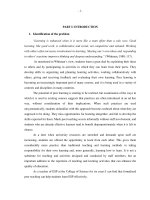
A very simple HLP is used in the example and the message format is indicated in Figure 1. The HLP uses
standard messages which contain eleven bit identifiers.
The upper three bits are ZERO which simplifies the
description to eight bits (e.g., ID = b’000 1010 0010’
becomes ID = b’1010 0010’ or A2h).
FIGURE 1:
BIT
10
MESSAGE FORMAT
BIT
0
0 0 0 NNNN 0 0 T T
N = NODE DESCRIPTION
T = MESSAGE TYPE
TT
00
01
10
11
ON BUS MSG
MOTOR CONTROL
AMBIENT LIGHT
MOTOR CURRENT
BASIC CONFIGURATION
While the MCP2510 is a relatively simple device to use,
the first time user may benefit from assistance in setting up the device for minimal configuration. With the
minimal configuration, designers can rapidly get on the
CAN bus and use the minimal configuration as a base
for the complete node design. This section will describe
a typical minimal configuration (not necessarily in
order) using example ‘C’ code to get the MCP2510 on
the CAN bus (i.e., transmitting and receiving messages
at the correct bit rate). The example does not discuss
the Higher Layer Protocol (HLP) in any detail as it is
beyond the scope of this document.
EXAMPLE 1:
Resetting the MCP2510
The first thing to do after device power-up is to reset the
MCP2510 and then wait the required oscillator startup
time (128 osc cycles). This step is good programming
practice to ensure that the MCP2510 is in a known
state. Reset forces the MCP2510 into the Configuration
mode. The MCP2510 must be in Configuration mode to
set the bit timing, masks and filters. Example 1 shows
sample code for issuing an MCP2510 Reset command
via the SPI interface bus.
RESET FUNCTION
void SPI_Reset(){
unsigned char SPIDummy;
SPI_CS = 0;
SSPBUF = SPI_RESET;
while (!STAT_BF;)
SPIDummy = SSPBUF;
SPI_CS = 1;
//Lower chip select
//Send the RESET command
// wait for ssp
for(SPIDummy = 0;SPIDummy < 128;SPIDummy ++);
//wait for OST
//Raise chip select
}
SPI™ is a trademark of Motorola Inc.
2001 Microchip Technology Inc.
DS00739A-page 1
AN739
Set Bit Timing
The bit timing is set via the three CNF registers. The
CNF registers can only be modified while in Configuration mode, which is automatically entered on power-up
or Reset. Example 2 shows sample code for setting the
MCP2510 to 125 kbps using a 16 MHz oscillator and
8 TQ.
EXAMPLE 2:
SET BIT TIMING
/* Set physical layer configuration
Fosc
= 16MHz
BRP
= 7 (divide by 8)
Sync Seg
= 1TQ
Prop Seg
= 1TQ
Phase Seg1
= 3TQ
Phase Seg2
= 3TQ
TQ = 2 * (1/Fosc) * (BRP+1)
Bus speed = 1/(Total # of TQ)*TQ = 125 kb/s
*/
SPI_Write(CNF1,0x07); //BRP = div by 8
SPI_Write(CNF2,0x90); //PSeg = 1TQ, PS1 = 3TQ
SPI_Write(CNF3, 0x02);//PS2 = 3TQ
fier field of the incoming message. Mask and filter
configuration plays a key role in implementing the
Higher Layer Protocol (HLP) that every CAN system
must have.
Some things that should be considered when configuring the masks and filters for the HLP are:
1.
2.
3.
Determine which message(s) will be received
for both standard and extended message types.
Determine which buffer each of the messages
will be loaded into.
Determine which filter will match each message.
This is particularly important if the message type
is determined by the filter that is matched. Filter
matching is done so the received message type
is known immediately without having to interrogate the ID (which takes time). This is demonstrated in Example 3, which shows filter
matching for different message types. Filter 2
receives LED status, filter 3 receives motor
speed, filter 4 receives ambient light conditions,
and filter 5 receives motor current.
Set Masks and Filters
MASKS AND FILTERS EXAMPLE
The masks and filters are used to determine if a message is accepted by the MCP2510, and if so, which
receive buffer will contain the message. This is accomplished by applying the masks and filters to the identi-
Example 3 illustrates a minimal mask and filter configuration required to communicate on the CAN bus. Keep
in mind that this example represents a very simple HLP.
In practice, HLPs can get much more complicated.
EXAMPLE 3:
SETTING MASKS AND FILTERS
/* Configure Receive buffer 0 Mask and Filters */
/* Receive buffer 0 will not be used */
SPI_Write(RXM0SIDH, 0xFF); // Set to all ‘1’s so filter
SPI_Write(RXM0SIDL, 0xFF); // Set to all ‘1’s so filter
SPI_Write(RXF0SIDH, 0xFF); // Set Filters to all ‘1’s
SPI_Write(RXF0SIDL, 0xFF); // The EXIDE bit is also set
SPI_Write(RXF1SIDH, 0xFF);
SPI_Write(RXF1SIDL, 0xFF); // The EXIDE bit is also set
must match every bit
must match every bit
to filter on extended msgs only
to filter on extended msgs only
/* Configure Receive Buffer 1 Mask and Filters */
SPI_Write(RXM1SIDH, 0xFF); // RXB1 matches all filters for Standard messages
SPI_Write(RXM1SIDL, 0xE0); //
//----------Receives LED message-----------------SPI_Write(RXF2SIDH, 0xA0); // Initialize Filter 2 (will receive only b'1010 0000 000' message)
SPI_Write(RXF2SIDL, 0x00); // Make sure EXIDE bit (bit 3) is set correctly in filter also
//----------Receives motor speed message ---------SPI_Write(RXF3SIDH, 0xA1); // Initialize Filter 3 (will receive only b'1010 0001 000' message)
SPI_Write(RXF3SIDL, 0x00); // Make sure EXIDE bit (bit 3) is set correctly in filter also
//----------Receives ambient light message ---------SPI_Write(RXF4SIDH, 0xA2); // Initialize Filter 4 (will receive only b'1010 0010 000' message)
SPI_Write(RXF4SIDL, 0x00); // Make sure EXIDE bit (bit 3) is set correctly in filter also
//----------Receives motor current message ---------SPI_Write(RXF5SIDH, 0xA3); // Initialize Filter 5 (will receive only b'1010 0011 000' message)
SPI_Write(RXF5SIDL, 0x00); // Make sure EXIDE bit (bit 3) is set correctly in filter also
DS00739A-page 2
2001 Microchip Technology Inc.
AN739
The HLP requirements for this example:
Note: A transmit buffer cannot be modified while
a message is either pending transmission
or currently transmitting from that buffer.
The corresponding TXREQ bit must be
clear prior to attempting to write to the
transmit buffer. The TXREQ bit is cleared
automatically when no messages are
pending transmission. Example 5 shows
the TXREQ bits for all three buffers being
checked [while(SPI_ReadStatus() &
0x54);] prior to entering the transmit load
loop.
• Will receive four different standard messages.
• Will use Receive Buffer 1 only (i.e., mask and filters for Buffer 0 are set to reject ALL messages).
• Each filter matches only one message. The message type will be determined by the filter hit bits
(FILHIT) instead of reading the identifier.
Note: The mask and filter for Receive Buffer 0
were set to all ‘1’s. This was done to effectively turn off Receive Buffer 0 from
receiving any messages, as incoming
message identifiers are applied to
Receive Buffer 0 mask and filters first, followed by Receive Buffer 1. The only way
for a message to be accepted by Receive
Buffer 0 would be if it was an extended
message with all ‘1’s for the identifier. The
filters apply to only extended IDs because
the extended identifier enable (EXIDE) bit
in RXFnSIDL is set to filter on extended
messages only and reject standard IDs
(see Figure 1).
Transmit Messages
Example 5 demonstrates transmitting both timed messages and event-driven messages.
As shown in Figure 1, there are four message types.
Two messages are timed transmissions and two are
event-driven:
On Bus Message → Timed → TXB0
Motor Control → Event-driven → TXB1
Ambient Light → Event-driven → TXB2
Motor Current → Timed →TXB0
Set Normal Mode
•
•
•
•
The MCP2510 can be placed in Normal mode once the
proper bit rate is set and the masks and filters are configured. This is accomplished by configuring the
REQOP bits in the CANCTRL register to the proper
value (REQOP<2:0> = b’000’).
The two event driven messages utilize their own transmit buffer and the identifier is set only once, while the
two timed messages share a transmit buffer. Therefore,
the identifiers are reconfigured as needed in the transmit loop.
Normal mode is the standard operating mode for communicating on the CAN bus. The MCP2510 then
acknowledges messages, applies the masks and filters, generates errors, etc.
Receive and Process Messages
Note: The operation mode must be confirmed
after requesting a mode. This is accomplished by reading CANSTAT.OPMOD
bits.
Set Transmit Buffers
The transmit buffers can be set before or after going to
Normal mode and only need to be configured once for
the portions of the message that remain constant. For
example, the identifier field may remain a constant
because it contains the message description, whereas
the data field may change due to varying peripherals.
Example 5 demonstrates both fixed and variable ID
fields.
There are four different messages that need to be sent
which requires one transmit buffer to contain two different identifiers. Transmit buffers one and two have fixed
identifiers and data length codes (DLCs) and are configured only once outside the transmit loop. Transmit
Buffer 0 sends two different messages. Thus, the identifiers are configured inside the transmit loop.
2001 Microchip Technology Inc.
The application must be set up to check for and process received messages that match the masks and filters. One method is illustrated in Example 5 where a
specific message is received into Receive Buffer 1 by
matching specific filters. Message reception is checked
by performing an SPI “Read Status” command. Since
only one message can match one filter, the filter hit bits
(FILHIT) can be used to determine the message type.
The RXB1SIDL register could just as easily be read
(RXB1SIDH will be the same) with the same end result.
Figure 5 contains the function “Check_RX()” which is
called in the function “Communicate()”. Again, the
reception of messages could utilize interrupts instead
of polling.
Note: The SPI “Read Status” command is a
quick two byte command that is very useful for checking for received messages.
As shown in Figure 5, a Read Status command:
[if(SPI_ReadStatus() & 0x02)] is
used to poll for a received message and
exits the function if the receive flag is
clear.
DS00739A-page 3
AN739
EXAMPLE 4:
TRANSMIT BUFFERS AND THE TRANSMIT LOOP
void Communicate(void)
{
unsigned char POTold, POTnew, CDSold, CDSnew, count, x;
/********************************************************************
*
Set up the identifiers for TX buffers 1 and 2 outside the
*
*
while() loop because they will never change. TX buffer 0
*
*
will change and so will need to be set up inside the loop.
*
*********************************************************************/
//---------Set up ’B1’ identifiers (TXB1) (ID remains constant)-----------SPI_Write(TXB1SIDH, 0xB1);
//Send ’B1’ type message
SPI_Write(TXB1SIDL, 0x00);
//Send ’B1’ type message
SPI_Write(TXB1DLC, 0x01);
//ONE data byte
//---------Set up ’B2’ identifiers (TXB2) (ID remains constant)----------SPI_Write(TXB2SIDH, 0xB2);
//Send ’B2’ type message
SPI_Write(TXB2SIDL, 0x00);
//Send ’B2’ type message
SPI_Write(TXB2DLC, 0x01);
//ONE data byte
//--------Note:
TXB0 identifiers will change and so must be set in the loop below---
while(1)
{
// Main control loop goes here
/************************************
*
Transmit the Messages
*
*************************************/
//----Wait for all buffers to complete transmission. This insures that ALL
//
buffers get sent each time through the loop.
while(SPI_ReadStatus() & 0x54);
//Wait for non-pending message (ALL BUFFERS)
//-Transmit Message ’B0’ ID once every 256 times through the loop (On Bus message)if(x == 0)
//has ’x’ overflowed??
{
SPI_Write(TXB0SIDH, 0xB0);
//Send ’B0’ type message
SPI_Write(TXB0SIDL, 0x00);
//Send ’B0’ type message
SPI_Write(TXB0DLC, 0x00);
//ZERO data bytes
SPI_Rts(RTS0);
//Transmit buffer 0
}
x++;
Check_RX();
//check for received msg
//-------Transmit ’B1’ type message
POTnew = Read_ADC(POT);
if(POTnew != POTold)
{
SPI_Write(TXB1D0, POTnew);
SPI_Rts(RTS1);
POTold = POTnew;
}
(motor control)-----------------/
//Read POT
//has POT value changed??
Check_RX();
//check for received msg
//-------Transmit ’B2’ type message
CDSnew = Read_ADC(CDS);
if(CDSnew != CDSold)
{
SPI_Write(TXB2D0, CDSnew);
SPI_Rts(RTS2);
CDSold = CDSnew;
}
(lamp control)-----------------/
Check_RX();
//check for received msg
//-------Transmit ’B3’ type message
while(SPI_ReadStatus() & 0x04);
SPI_Write(TXB0SIDH, 0xB3);
SPI_Write(TXB0SIDL, 0x00);
SPI_Write(TXB0DLC, 0x01);
SPI_Write(TXB0D0, Read_ADC(MCS));
SPI_Rts(RTS0);
(Motor current) (ID changes)----------------/
//Wait for non-pending message (TXB0)
//Send ’B3’ type message
//Send ’B3’ type message
//ONE data byte
//Read motor curret, send value
//Transmit buffer 2
Check_RX();
//send motor speed
//Transmit buffer 1
//has CDS changed??
//Read CDS, send light level
//Transmit buffer 2
//update CDSold
//check for received msg
}; //END while()
}
DS00739A-page 4
2001 Microchip Technology Inc.
AN739
EXAMPLE 5:
PROCESSING RECEIVED MESSAGES
void Check_RX(void)
{
unsigned char filter;
if(SPI_ReadStatus() & 0x02)
{
filter = SPI_Read(RXB1CTRL) & 0x07;
//ID: A0 = >On Bus message
if(filter == 2)
LED1 = !LED1;
//ID: A1 => Set motor speed
else if(filter == 3)
{
Update_PWM2(SPI_Read(RXB1D0));
}
//ID: A2 => Set lamp to ambient light
else if(filter == 4)
{
Update_PWM1(SPI_Read(RXB1D0));
}
//ID: A3 => display motor current
else if(filter == 5)
{
BarGraph_Level(SPI_Read(RXB1D0));
}
SPI_BitMod(CANINTF, RX1IF, 0);
}
}
2001 Microchip Technology Inc.
//Was a message received into buffer 1??
//Read FILHIT bits
//Filter hit 2 ??
//Toggle LED1
//Filter hit 3 ??
//Set motor speed to contents of data byte 0
//Filter hit 4 ??
//Set lamp brightness to contents of data byte 0
//Filter hit 5 ??
//Show motor current to contents of data byte 0
//Clear receive buffer 1 interrupt
DS00739A-page 5
AN739
ADDITIONAL MCP2510 DETAILS
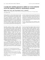
FIGURE 2:
The previous section discussed a minimal configuration of the MCP2510 to communicate on the CAN bus.
The feature set of the MCP2510 allows the designer to
customize the MCP2510 configuration for optimal performance to the application. This section discusses
some of the other configurations possible with the
MCP2510. The last part of this section discusses the
SPI commands. Another section later in this document
contains more details on the registers. A designer
should be able to use some of these configurations to
maximize the performance of the MCP2510.
Resetting the MCP2510
There are two methods to reset the MCP2510:
1.
2.
Software SPI Reset command as done in
Example 1.
Hardware Reset pin.
Both of these Reset methods have identical end results
and must wait the 128 Tosc time for the oscillator startup timer (OST).
Setting Bit Timing
When configuring the bit timing, several things must be
considered for the MCP2510 to function properly. This
section does not discuss the physical layer considerations, but only the bit timing requirements as needed
by the CAN module.
SOME BACKGROUND
SYNC
SEG PROPSEG
1 TQ
Synchronization Segment (SyncSeg).
Propagation Segment (PropSeg).
Phase Segment 1 (PS1).
Phase Segment 2 (PS2).
Each of these segments are made up of integer units
called Time Quanta (TQ). The base TQ is defined as 2
Tosc. The TQ time can be modified by changing the
“Baud Rate Prescaler”.
DS00739A-page 6
PS2
1 - 8 TQ
2 - 8 TQ
There are additional definitions that are needed to
understand the bit timing settings:
• Information Processing Time (IPT) - The time it
takes to determine the value of the bit. The IPT
occurs after the sample point and is fixed at 2 TQ.
• Synchronization Jump Width (SJW) - Can be
programmed from 1 - 4 TQ and is the amount that
PS1 can lengthen or PS2 can shorten so the
receiving node can maintain synchronization with
the transmitter.
• Bus Delay Times (TDELAY) - This delay time is
the physical delays as a result of the physical
layer (length, material, transceiver characteristics,
etc).
RULES FOR SETTING THE BIT TIME
There are four rules that must be adhered to when programming the timing segments:
1.
2.
3.
The sample point occurs between PS1 and PS2 and is
the point where the bit level is sampled to determine
whether it is dominant or recessive.
By changing the TQ number in the bit segments and/or
the baud rate prescaler, it is possible to change the bit
length and move the sample point around in the bit.
Figure 2 shows the components of a bit.
1 - 8 TQ
PS1
Sample
Point
Every bit time is made up of four segments:
1.
2.
3.
4.
CAN BIT COMPONENT
4.
PS2 ≥ IPT: Phase Segment 2 must be greater
than or equal to the Information Processing
Time (IPT) so that the bit level can be determined and processed by the CAN module
before the beginning of the next bit in the
stream. The IPT = 2 TQ so PS2(min) = 2 TQ.
PropSeg + PS1 ≥ PS2: This requirement
ensures the sample point is greater than 50% of
the bit time.
PS2 > SJW: PS2 must be larger than the SJW
to avoid shortening the bit time to before the
sample point. For example, if PS2 = 2 and
SJW = 3, then a resynchronization to shorten
the bit would place the end of the bit time at 1 TQ
before the sample point.
PropSeg + PS1 ≥ TDELAY: This requirement
ensures there is adequate time before the sample point. In fact, the PropSeg should be set to
compensate for physical bus delays.
2001 Microchip Technology Inc.
AN739
Setting Masks and Filters
3.
The earlier example demonstrates only one way to lock
out a receive buffer by setting the mask and filter bits to
all ‘1’s. Two other ways to reject all messages from
being received into a specified buffer. Register 1 shows
the two other registers that control message filtering/
acceptance.
1.
2.
Configure RXBnCTRL.RXM bits. Instead of writing all ‘1’s to the mask and filter bits for a specified buffer, as shown in the example code, the
RXM bits can be configured to accept or reject
message types. For example, the RXM bits for
Buffer 0 could be configured to receive only.
extended identifiers that match mask and filter
criteria (RXM = b’10’). This would effectively lock
out message reception for receive Buffer 0
because only standard identifiers are used in the
example.
Configure the Extended Identifier Enable
(EXIDE) bit for each filter that is to reject messages to the opposite identifier type that is on
the CAN bus. Each filter is applied to either
extended or standard messages and is controlled by the EXIDE bit which is contained in the
RXFnSIDL registers. By setting the mask and filter bits in the example, the EXIDE bit is also set
which prevents standard messages from being
filtered on.
The MCP2510 has five modes of operation:
2.
Configuration Mode - Automatically entered
upon power-up or reset. This is the only mode
that can write all writable registers. The bit timing registers and the masks and filters can only
be modified while the MCP2510 is in Configuration mode.
Normal Mode - As the name implies, this is the
normal mode of operation. The MCP2510 can
actively communicate on the bus in this mode.
REGISTER 1:
Note 1: The CLKOUT pin stops functioning during Sleep mode.
2: The SPI interface remains active during
Sleep mode.
4.
Listen-only Mode - This mode allows the
MCP2510 to monitor the bus without disturbing
it (i.e., it cannot send messages, acknowledges,
or error frames on the bus).
Masks and filters work in this mode as does the
ability to accept all messages, including those with
errors (RXBnCTRL.RXM<1:0> = b’11’).
Listen-only mode can be used for auto baud rate
detection by empirically changing to different baud
rates and listening for an error-free message.
5.
Loopback Mode - This mode internally disconnects the TXCAN and RXCAN pins and connects them to each other. In this way, CAN traffic
can be simulated by sending messages to itself.
This mode has few practical uses in customer
designed applications.
The Transmit Buffers
Modes of Operation
1.
Sleep Mode - This mode is used to minimize
current consumption. Sleep mode would typically be used during long bus idle times although
it could also be used to put the device to sleep
during bus activity by disabling the interrupt
enable (CANINTE.WAKIE).
As discussed in the previous example, the transmit
buffers can be set to a fixed ID or can be changed
dynamically, allowing more than one identifier to be
used in conjunction with a buffer.
The MCP2510 does not have to be in Configuration
mode to modify the buffers. However, the associated
transmit request (TXREQ) bit must be cleared before
the transmit buffer can be modified. The TXREQ bit is
cleared automatically whenever a buffer is not pending/
sending a message.
CONTROLLING MESSAGE FILTERING
---
RXB0CTRL
RXM1
RXM0
---
RXRTR
BUKT
BUKT1
bit 7
---
RXB1CTRL
bit 0
RXM1
RXM0
---
RXRTR
FILHIT2 FILHIT1 FILHIT0
bit 7
RXFnSIDL
SID2
bit 7
2001 Microchip Technology Inc.
FILHIT0
bit 0
SID1
SID0
---
EXIDE
---
EID17
EID16
bit 0
DS00739A-page 7
AN739
Transmitting a Message
There are three methods to request transmission of a
message (two software and one hardware):
1.
2.
3.
Request to Send via SPI RTS command. This is
a single byte command used to initiate transmission of one or more buffers simultaneously. In
the event multiple buffers are requested at the
same time, the buffers will be sent according to
the buffer priority (discussed later in more
detail).
Set a TXREQ bit in a TXBnCTRL register via a
SPI Write command or a SPI Bit Modify command. This method is not as efficient as the SPI
RTS command as it requires three bytes (SPI
Write) or four bytes (Bit Modify) via the SPI. Furthermore, the Bit Modify command should be
used if the other writable bits are not to be disturbed.
Provide a falling edge on the appropriate
TXnRTS pin assuming the pin is configured as
an RTS input. This can be used to quickly
request a preconfigured buffer to be transmitted.
BUFFER PRIORITY
If more than one buffer is requesting transmission
(TXREQ) at the same time, the message with the highest buffer priority gets sent first. The buffer priority is
not to be confused with the inherent message priority
contained in the identifier field. Buffer priority is set via
TxBnCTRL.TXP. If multiple buffers have the same priority setting, the buffer with the highest buffer number
will be sent first.
There are several methods for processing received
messages. This section discusses these methods individually; some of them may be combined as required
by the designer.
DETERMINING IF A MESSAGE HAS BEEN
RECEIVED
There are two main methods for determining if a message has been received by the MCP2510:
1.
Check the receive
INTF.RXnIF).
buffer
flags
(CAN-
The methods to accomplish this are:
a.
b.
Performing an SPI “Read Status” command.
This method gives the ability to quickly read the
two RXnIF bits and is the preferred method.
Directly reading the receive flag bits (RXnIF) in
the CANINTF register.
Note: The associated enable bit (RXnIE) in the
CANINTE register does not need to be set
for the flag bits to function. CANINTE is
used to enable the INT pin for hardware
interrupts.
2. Hardware interrupt using the INT pin.
The MCP2510 has eight sources of interrupts, two of
which indicate message reception. For interrupts to be
enabled, the two CANINTE.RXnIE bits must be set.
The associated flag bit conditions will be reflected in
the CANINTF register.
PROCESSING RECEIVED MESSAGES
This buffer prioritization occurs if two or more buffers
are requested to transmit, and every time the
MCP2510 arbitrates (i.e., if a message loses arbitration
and must rearbitrate, the MCP2510 will check for
higher priority buffers that became pending).
Once a message has been received, it must be processed to determine which buffer received the message and what the message type is. There are many
different combinations that can be used for processing
received messages. These descriptions only identify
the common methods.
Receiving and Processing Messages
There are numerous ways to determine which buffer
contains the message:
The message acceptance filters and masks are used to
determine if a message in the message assembly
buffer (MAB) should be loaded into either receive
buffer. Once a valid message has been loaded into the
MAB, the identifier fields of the message are compared
to the filter values. If a match occurs, the message is
moved into the appropriate receive buffer.
Note: The mask and filters for Receive Buffer 0
are compared first. If there is a match, the
message is moved into Receive Buffer 0
and Receive Buffer 1 filters are not
checked. This implies that the message
will be received into a maximum of one
buffer only.
DS00739A-page 8
• Perform an SPI “Read Status” command. This
command provides the status of the two receive
flags (among others).
• Directly read CANINTF for RXnIF status.
• Read the ICOD bits in CANSTAT. This method
requires the associated enables in CANINTE be
set.
• Check the level of the RXnBF pins. This requires
the two pins to be configured as buffer interrupts
(BFPCTRL register).
After the location of the received message is known, it
is necessary to determine the purpose of the message.
Assuming that more than one message type will be
received into a given buffer, there are a few methods to
determine the message type:
2001 Microchip Technology Inc.
AN739
• Read the identifier. There are up to four registers
that make up the ID field (two for standard messages and four for extended messages). One or
all registers may need to be read to determine the
message type, depending on how the higher layer
protocol was implemented.
• Read the FILHIT bits. The FILHIT bits are contained in RXB0CTRL and RXB1CTRL. The
FILHIT bits can be used to quickly determine the
message type (providing only one message ID
per filter).
• Some systems may be set to receive only one
message ID into a given receive buffer. In this
case, it is only necessary to determine if the message was received into that buffer and then the
message type known.
THE SERIAL PERIPHERAL
INTERFACE (SPI)
Communications with the MCP2510 is performed via
an SPI interface. The MCP2510 supports both modes
0,0 and 1,1. It also contains several commands to efficiently access the MCP2510.
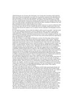
Modes 0,0 and 1,1
The two SPI modes supported by the MCP2510 are
almost identical. The only difference is the idle state of
the serial clock (SCK). The idle state of SCK for mode
0,0 is LOW and the idle state for mode 1,1 is HIGH.
Both modes are the same in that data is latched into the
MCP2510 (SI pin) on the rising edge of SCK and
clocked out (SO pin) on the falling edge of SCK.
Figure 3 illustrates the SPI timing for the two modes of
operation.
FIGURE 3:
SPI TIMING
SPI Reset
The SPI Reset command performs the same function
as a hardware reset. Thus, all of the registers will be initialized to their default state and the MCP2510 will be
held in reset for 128 oscillator cycles. It is important to
wait the 128 oscillator cycles before attempting any
more SPI commands.
SPI Read
This command reads one or more registers in the
device register map. SPI Reads can be byte or sequential. Sequential reads are performed simply by holding
Chip Select (CS) LOW and continuing to clock SCK.
The address pointer will increment after each byte is
clocked out.
SPI Write
This command writes data to one or more registers in
the device register map. SPI Writes can be byte or
sequential. Sequential writes are performed simply by
holding Chip Select (CS) LOW and continuing to clock
data into SI. The address pointer will increment after
each byte of data is clocked in.
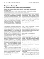
Request to Send (RTS)
The RTS command is a quick one byte method for initiating transmit requests. The RTS command sets the
TXREQ bit for one or more transmit buffers by setting
the appropriate bit(s) as shown in Figure 4.
FIGURE 4:
SPI RTS COMMAND
1000 0nnn
Request to send
for TXB2
Request to send
for TXBO
Request to send for TXB1
CS
SPI Read Status
Mode 1,1
SCK
SI
SO
Mode 0,0
Data in
Data out
Chip Select (CS)
The CS line must be brought high at the end of every
command. This allows the next command to be recognized as the 1st byte after the CS is asserted. With
some commands (e.g. read, write), after the command
sequence is completed, the internal address pointer is
incremented and the next byte may be read or write.
2001 Microchip Technology Inc.
The Read Status command offers a quick method for
reading some of the often used bits in the MCP2510.
The transmit flag bits (TXnIF) and the receive flag bits
(RXnIF) are mapped from the CANINTF register, as are
the transmit request bits (TXREQ) from the TXBnCTRL
registers.
Using the Read Status command to check for receive
status/buffers and for checking for pending transmit
buffers is very useful. As shown in Example 5, a simple
“if()” statement can be used to check for received messages. Also shown in Example 4 is a “while()” statement that waits for the transmit buffers to be nonpending before attempting to write to them. Recall that
the transmit buffers cannot be modified while a message is pending or transmitting from the buffer in question.
DS00739A-page 9
AN739
REGISTER DISCUSSION
Refer to the MCP2510 Datasheet (DS21291) for more
information on the registers and associated bits.
The previous sections discussed specific methods for
performing functions on the MCP2510. This section is
devoted to looking at many of the registers in the
MCP2510 and discussing their features, along with the
more important bits or the bits which are most likely to
generate questions.
REGISTER 2:
TXBNCTRL REGISTER
---
ABTF
MLOA
TXERR
TXREQ
--
TXP1
bit 7
TXP0
bit 0
TXERR - An error frame (from the MCP2510 or a receiver) was generated while the MCP2510 was transmitting
a message.
TXREQ - Setting this bit initiates a request for transmission. The actual transmission may occur later than when
the bit was initially set to avoid violating the CAN protocol. The bit will clear after the buffer finishes a successful
transmission.
TXPn - Sets the transmit buffer priority. If multiple buffers are requested simultaneously for transmission, the
higher priority buffer will be sent first.
11 = Highest.
10 = High intermediate.
01 = Low intermediate.
00 = Lowest.
In the event that multiple buffers have the same priority, the higher buffer number will be the higher priority.
For example, TxB2 has a higher priority than TxB1 and TxB0.
REGISTER 3:
TXRTSCTRL REGISTER
---
--
B2RTS
B1RTS
B0RTS B2RTSM B1RTSM B0RTSM
bit 7
bit 0
BnRTS - Reflects the state of the associated pin while configured as a digital input; otherwise reads as a ZERO.
BnRTSM - Configures the pins as either digital input or as buffer request-to-transmit. Messages are initiated on
the falling edge of the associated enabled TXnRTS pin.
Note:
The pins have a nominal 100 kΩ nominal pull-up resistor.
REGISTER 4:
TXBNSIDL REGISTER
SID2
SID1
SID0
---
EXIDE
---
bit 7
EID17
EID16
bit 0
EXIDE - Selects whether the transmitted message is standard or extended.
DS00739A-page 10
2001 Microchip Technology Inc.
AN739
REGISTER 5:
RXBNCTRL REGISTER
---
RXM1
RXM0
---
RXRTR
BUKT
BUKT1
FILHIT0
bit 7
bit 0
---
RXM1
RXM0
---
RXRTR
FILHIT2
FILHIT1
FILHIT0
bit 7
bit 0
RXMn - Determine the masks and filters operating mode. These bits can be configured:
11 = Turn mask and filters off; receive any message.
10 = Filter on only extended messages, reject standard messages.
01 = Filter on only standard messages, reject extended messages.
00 = filter on both standard and extended messages.
RXRTR - Indicates if the message was a Remote Frame (RTR).
BUKT - If set, will enable messages destined for receive buffer 0 (RXB0) to be rolled over into receive buffer 1
(RXB1), if RXB0 is full and RXB1 is empty.
FILHITn - Indicates which filter matched the last received message. Useful for determining the message type
without reading the identifier, if each filter only matches one message type.
Note: Care must be taken when setting the RXFnSIDL.EXIDE bit and the RXBnCTRL.RXM bits to insure
proper operation. For example, if the EXIDE bit is configured to filter on standard frames, then the
RXM bits must not be configured to receive only extended frames (RXM<1:0> = 10) or no messages will be received.
Note: Setting RXM<1:0> = 11 turns masks and filters off to allow reception of all messages, including messages with errors. If an error occurs on the bus, the portion of the message up to the error will be
loaded into the receive buffer.
REGISTER 6:
BFPCTRL REGISTER
---
---
B1BFS
B0BFS
B1BFE
B0BFE
B1BFM
bit 7
B0BFM
bit 0
BnBFS - Sets the pin state, if the pin is enabled and configured as an output.
BnBFE - Enables/disables the pin (The mode is set with the BnBFM bits).
BnBFM - Sets the pin mode to either digital output or RX buffer interrupt (must be enabled with the BnBFE).
2001 Microchip Technology Inc.
DS00739A-page 11
AN739
REGISTER 7:
RXBNSIDL REGISTER
SID2
SID1
SID0
SRR
IDE
---
EID17
bit 7
EID16
bit 0
SRR - Indicates if a standard remote frame was received (the indicator for extended remote frames is contained in RXBnDLC).
IDE - If set, indicates that the received message was an extended frame.
REGISTER 8:
RXBNDLC REGISTER
---
RTR
RB1
RB0
DLC3
DLC2
DLC1
DLC0
bit 7
bit 0
RTR - Indicates if an extended remote frame was received (the indicator for standard remote frames is contained in RXBnSIDL).
REGISTER 9:
RXFNSIDL REGISTER
SID2
SID1
SID0
---
EXIDE
---
EID17
bit 7
EID16
bit 0
EXIDE - Determines whether the filter applies to standard or extended frames.
Note: Care must be taken when setting the RXFnSIDL.EXIDE bit and the RXBnCTRL.RXM bits to
insure proper operation. For example, if the EXIDE bit is configured to filter on standard frames,
then the RXM bits must not be configured to receive only extended frames (RXM<1:0> = 10) or
no messages will be received.
DS00739A-page 12
2001 Microchip Technology Inc.
AN739
REGISTER 10:
CNF1, CNF2 AND CNF3 REGISTERS
SJW1
SJW0
BRP5
BRP4
BRP3
BRP2
BRP1
BRP0
bit 0
bit 7
SJW<1:0> - Sets the Synchronization Jump Width. The SJW is the number of TQ the bit time will be lengthened
or shortened due to resynchronization during message reception. SJW is programmable from 1 - 4 TQ.
BRP <5:0> - Sets the length of each TQ. Programmable from 2 - 128 Tosc using the formula:
TQlength = 2*(BRP + 1) * Tosc; where BRP = the value programmed into CNF1.BRP<5:0>.
BTLMODE
SAM
PHSEG12 PHSEG11 PHSEG10 PRSEG2
PRSEG1
PRSEG0
bit 0
bit 7
BTLMODE - Determines if Phase Segment 2 (PS2) is set by the bits in CNF3 or the value of Phase Segment 1
(PS1) or the Information Processing Time (IPT). This bit must be SET to program PS2 via CNF3, otherwise PS2
will be set to the greater of PS1 or the IPT.
SAM - Sets the number of times (one or three) the bus level will be sampled within each bit. If set to three, the
bus sampled three times at 0.5 TQ intervals staring 1 TQ before PS2. The value is determined by the majority
level. Sampling three times was intended to compensate for noisy busses and should only be used at slower
bus rates.
PHSEG1<2:0> - Programs Phase Segment 1 (PS1) from 1 - 8 TQ.
PRSEG<2:0> - Programs the Propagation Segment from 1 - 8 TQ.
---
WAKFIL
---
---
---
PHSEG22 PHSEG21 PHSEG20
bit 7
bit 0
WAKFIL - Enables/disables the wake-up noise filter. When enabled, noise pulses of less than 50 ns on the
RXCAN pin are filtered out, while the MCP2510 is in Sleep mode.
PHSEG2<2:0> - Programs Phase Segment 2 (PS2) from 2 - 8 TQ.
2001 Microchip Technology Inc.
DS00739A-page 13
AN739
REGISTER 11:
CANINTE AND CANINTF REGISTERS (INTERRUPT ENABLES AND FLAGS)
MERRE
WAKIE
ERRIE
TX2IE
TX1IE
TX0IE
RX1IE
RX0IE
bit 0
bit 7
MERRF
WAKIF
ERRIF
TX2IF
TX1IF
TX0IF
RX1IF
RX0IF
bit 0
bit 7
Note: CANINTE contains the interrupt enables which causes a hardware interrupt and maps to the
CANSTAT.ICOD bits if the associated flag bit is set.
CANINTF contains the flag bits which are set regardless of the value of the associated enable
bit. The flag bits are both readable and writable, so care must be taken when modifying this register. The SPI “Bit Modify” command works well with these registers.
MERRE/F - Message error interrupt/flag will be set if the MCP2510 sees a transmit or receive error on the bus.
WAKIE/F - Indicates the MCP2510 woke up from Sleep.
ERRIE/F - Indicates a flag in the EFLG register was set.
TXnIE/F - Indicates the successful transmission of a message. The flag does not need to be cleared to reload
and transmit a message.
RXnIE/F - Indicates a message reception. The flag MUST be cleared by the MCU in order to receive a message. This acts as a positive lockout to keep incoming message from overwriting a received message.
REGISTER 12:
CANCTRL REGISTER
REQOP2
REQOP1
REQOP0
ABAT
---
CLKEN
CLKPRE1 CLKPRE0
bit 0
bit 7
REQOP<2:0> - Requests the operating mode of the MCP2510. The current mode of operation MUST be
checked using CANSTAT.OPMOD not with the REQOP bits.
ABAT - Requests abort of all pending transmit buffers. This bit MUST be cleared to transmit further messages.
CLKEN - Enables/disables the CLKOUT pin.
CLKPRE<1:0> - Sets the CLKOUT prescaler to Fosc/1, Fosc/2, Fosc/4, or Fosc/8.
Note:
On power-up, the REQOP bits will read b’111’ indicating Configuration mode was requested. At
all other times, this value is invalid and unexpected results will occur if set to this value. To
request Configuration mode REQOP = b’100’.
DS00739A-page 14
2001 Microchip Technology Inc.
AN739
REGISTER 13:
CANSTAT REGISTER
OPMOD2 OPMOD1 OPMOD0
---
ICOD2
ICOD1
ICOD0
---
bit 0
bit 7
OPMOD<2:0> - Reflects the current operating mode. These bits are checked (not CANCTRL.REQOP) for the
current operating mode.
ICOD<2:0> - The interrupt code bits reflect the highest priority pending interrupt. If multiple interrupts are pending and the highest is cleared, the next highest will be rejected.
SUMMARY
REFERENCES
While this application note does not cover all methods
for configuring and operating the MCP2510, it can be a
reference to help operate the device in a suitable manner for a given application. There are a some main
points to remember when using the MCP2510:
Robert Bosch GmbH, CAN Specification Version 2.0,
1991.
• Wait 128 OSC cycles after performing a Reset.
• Must be in Configuration mode to modify the bit
timing registers (CNFn) and the masks and filters.
• Make sure the receive mode (RXBnCTRL.RXM)
matches the masks and filters settings. The
default is “Receive all valid messages (standard
and extended) that match masks and filters”.
• Configure interrupt enables as needed (CANINTE).
• Set Normal mode before attempting to communicate on the bus.
• Use the SPI “Bit Modify” command where applicable to avoid disturbing bits unintentionally.
• The transmit buffers cannot be modified when its
respective TXREQ bit is set indicating the buffer is
pending or is currently transmitting.
• Use SPI “Read Status” to check received messages and pending transmit buffers.
• Entering Sleep mode disables the CLKOUT pin.
• The SPI interface is still active when the
MCP2510 is in Sleep mode.
• The TX0RTS, TX1RTS, TX2RTS pins have
100 kΩ nominal pull-up resistors.
2001 Microchip Technology Inc.
MCP2510 Data
Technology, Inc.
Sheet,
DS21291,
Microchip
Lawrenz, Wolfhard, CAN Systems Engineering From
Theory to Practical Applications, Springer, 1997.
DS00739A-page 15
AN739
NOTES:
DS00739A-page 16
2001 Microchip Technology Inc.
AN739
NOTES:
2001 Microchip Technology Inc.
DS00739A-page 17
AN739
NOTES:
DS00739A-page 18
2001 Microchip Technology Inc.
AN739
“All rights reserved. Copyright © 2001, Microchip
Technology Incorporated, USA. Information contained
in this publication regarding device applications and the
like is intended through suggestion only and may be
superseded by updates. No representation or warranty
is given and no liability is assumed by Microchip
Technology Incorporated with respect to the accuracy
or use of such information, or infringement of patents or
other intellectual property rights arising from such use
or otherwise. Use of Microchip’s products as critical
components in life support systems is not authorized
except with express written approval by Microchip. No
licenses are conveyed, implicitly or otherwise, under
any intellectual property rights. The Microchip logo and
name are registered trademarks of Microchip
Technology Inc. in the U.S.A. and other countries. All
rights reserved. All other trademarks mentioned herein
are the property of their respective companies. No
licenses are conveyed, implicitly or otherwise, under
any intellectual property rights.”
Trademarks
The Microchip name, logo, PIC, PICmicro,
PICMASTER, PICSTART, PRO MATE, KEELOQ,
SEEVAL, MPLAB and The Embedded Control
Solutions Company are registered trademarks of
Microchip Technology Incorporated in the U.S.A. and
other countries.
Total Endurance, ICSP, In-Circuit Serial Programming,
FilterLab, MXDEV, microID, FlexROM, fuzzyLAB,
MPASM, MPLINK, MPLIB, PICDEM, ICEPIC,
Migratable Memory, FanSense, ECONOMONITOR,
SelectMode and microPort are trademarks of
Microchip Technology Incorporated in the U.S.A.
Serialized Quick Term Programming (SQTP) is a
service mark of Microchip Technology Incorporated in
the U.S.A.
All other trademarks mentioned herein are property of
their respective companies.
© 2001, Microchip Technology Incorporated, Printed in
the U.S.A., All Rights Reserved.
Microchip received QS-9000 quality system
certification for its worldwide headquarters,
design and wafer fabrication facilities in
Chandler and Tempe, Arizona in July 1999. The
Company’s quality system processes and
procedures are QS-9000 compliant for its
PICmicro® 8-bit MCUs, KEELOQ® code hopping
devices, Serial EEPROMs and microperipheral
products. In addition, Microchip’s quality
system for the design and manufacture of
development systems is ISO 9001 certified.
2001 Microchip Technology Inc.
DS00739A-page 19
WORLDWIDE SALES AND SERVICE
AMERICAS
New York
Corporate Office
150 Motor Parkway, Suite 202
Hauppauge, NY 11788
Tel: 631-273-5305 Fax: 631-273-5335
2355 West Chandler Blvd.
Chandler, AZ 85224-6199
Tel: 480-792-7200 Fax: 480-792-7277
Technical Support: 480-792-7627
Web Address:
Rocky Mountain
2355 West Chandler Blvd.
Chandler, AZ 85224-6199
Tel: 480-792-7966 Fax: 480-792-7456
Atlanta
500 Sugar Mill Road, Suite 200B
Atlanta, GA 30350
Tel: 770-640-0034 Fax: 770-640-0307
Austin
Analog Product Sales
8303 MoPac Expressway North
Suite A-201
Austin, TX 78759
Tel: 512-345-2030 Fax: 512-345-6085
Boston
2 Lan Drive, Suite 120
Westford, MA 01886
Tel: 978-692-3848 Fax: 978-692-3821
Boston
Analog Product Sales
Unit A-8-1 Millbrook Tarry Condominium
97 Lowell Road
Concord, MA 01742
Tel: 978-371-6400 Fax: 978-371-0050
Chicago
333 Pierce Road, Suite 180
Itasca, IL 60143
Tel: 630-285-0071 Fax: 630-285-0075
Dallas
4570 Westgrove Drive, Suite 160
Addison, TX 75001
Tel: 972-818-7423 Fax: 972-818-2924
Dayton
Two Prestige Place, Suite 130
Miamisburg, OH 45342
Tel: 937-291-1654 Fax: 937-291-9175
Detroit
Tri-Atria Office Building
32255 Northwestern Highway, Suite 190
Farmington Hills, MI 48334
Tel: 248-538-2250 Fax: 248-538-2260
Los Angeles
18201 Von Karman, Suite 1090
Irvine, CA 92612
Tel: 949-263-1888 Fax: 949-263-1338
Mountain View
Analog Product Sales
1300 Terra Bella Avenue
Mountain View, CA 94043-1836
Tel: 650-968-9241 Fax: 650-967-1590
ASIA/PACIFIC (continued)
Korea
Microchip Technology Korea
168-1, Youngbo Bldg. 3 Floor
Samsung-Dong, Kangnam-Ku
Seoul, Korea
Tel: 82-2-554-7200 Fax: 82-2-558-5934
San Jose
Microchip Technology Inc.
2107 North First Street, Suite 590
San Jose, CA 95131
Tel: 408-436-7950 Fax: 408-436-7955
Singapore
Microchip Technology Singapore Pte Ltd.
200 Middle Road
#07-02 Prime Centre
Singapore, 188980
Tel: 65-334-8870 Fax: 65-334-8850
Toronto
6285 Northam Drive, Suite 108
Mississauga, Ontario L4V 1X5, Canada
Tel: 905-673-0699 Fax: 905-673-6509
Taiwan
Microchip Technology Taiwan
11F-3, No. 207
Tung Hua North Road
Taipei, 105, Taiwan
Tel: 886-2-2717-7175 Fax: 886-2-2545-0139
ASIA/PACIFIC
Australia
Microchip Technology Australia Pty Ltd
Suite 22, 41 Rawson Street
Epping 2121, NSW
Australia
Tel: 61-2-9868-6733 Fax: 61-2-9868-6755
EUROPE
China - Beijing
Denmark
Microchip Technology Beijing Office
Unit 915
New China Hong Kong Manhattan Bldg.
No. 6 Chaoyangmen Beidajie
Beijing, 100027, No. China
Tel: 86-10-85282100 Fax: 86-10-85282104
Microchip Technology Denmark ApS
Regus Business Centre
Lautrup hoj 1-3
Ballerup DK-2750 Denmark
Tel: 45 4420 9895 Fax: 45 4420 9910
France
China - Shanghai
Microchip Technology Shanghai Office
Room 701, Bldg. B
Far East International Plaza
No. 317 Xian Xia Road
Shanghai, 200051
Tel: 86-21-6275-5700 Fax: 86-21-6275-5060
Hong Kong
Microchip Asia Pacific
RM 2101, Tower 2, Metroplaza
223 Hing Fong Road
Kwai Fong, N.T., Hong Kong
Tel: 852-2401-1200 Fax: 852-2401-3431
India
Microchip Technology Inc.
India Liaison Office
Divyasree Chambers
1 Floor, Wing A (A3/A4)
No. 11, O’Shaugnessey Road
Bangalore, 560 025, India
Tel: 91-80-2290061 Fax: 91-80-2290062
Japan
Microchip Technology Intl. Inc.
Benex S-1 6F
3-18-20, Shinyokohama
Kohoku-Ku, Yokohama-shi
Kanagawa, 222-0033, Japan
Tel: 81-45-471- 6166 Fax: 81-45-471-6122
Arizona Microchip Technology SARL
Parc d’Activite du Moulin de Massy
43 Rue du Saule Trapu
Batiment A - ler Etage
91300 Massy, France
Tel: 33-1-69-53-63-20 Fax: 33-1-69-30-90-79
Germany
Arizona Microchip Technology GmbH
Gustav-Heinemann Ring 125
D-81739 Munich, Germany
Tel: 49-89-627-144 0 Fax: 49-89-627-144-44
Germany
Analog Product Sales
Lochhamer Strasse 13
D-82152 Martinsried, Germany
Tel: 49-89-895650-0 Fax: 49-89-895650-22
Italy
Arizona Microchip Technology SRL
Centro Direzionale Colleoni
Palazzo Taurus 1 V. Le Colleoni 1
20041 Agrate Brianza
Milan, Italy
Tel: 39-039-65791-1 Fax: 39-039-6899883
United Kingdom
Arizona Microchip Technology Ltd.
505 Eskdale Road
Winnersh Triangle
Wokingham
Berkshire, England RG41 5TU
Tel: 44 118 921 5869 Fax: 44-118 921-5820
01/30/01
All rights reserved. © 2001 Microchip Technology Incorporated. Printed in the USA. 3/01
Printed on recycled paper.
Information contained in this publication regarding device applications and the like is intended through suggestion only and may be superseded by
updates. It is your responsibility to ensure that your application meets with your specifications. No representation or warranty is given and no liability is
assumed by Microchip Technology Incorporated with respect to the accuracy or use of such information, or infringement of patents or other intellectual
property rights arising from such use or otherwise. Use of Microchip’s products as critical components in life support systems is not authorized except with
express written approval by Microchip. No licenses are conveyed, implicitly or otherwise, except as maybe explicitly expressed herein, under any intellectual property rights. The Microchip logo and name are registered trademarks of Microchip Technology Inc. in the U.S.A. and other countries. All rights
reserved. All other trademarks mentioned herein are the property of their respective companies.
DS00739A-page 20
2001 Microchip Technology Inc.