AN0740 decoding the HCS101 for non secure applications
Bạn đang xem bản rút gọn của tài liệu. Xem và tải ngay bản đầy đủ của tài liệu tại đây (221.35 KB, 18 trang )
AN740
Decoding the HCS101 for Non-Secure Applications
FIGURE 1:
Reston Condit
Microchip Technology, Inc.
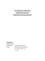
DECODER PIN-OUT
PDIP, SOIC
OVERVIEW
VDD
1
This application note describes the working of a
decoder for the HCS101 fixed-code encoder. The
decoder is implemented on Microchip’s smallest 8-pin
microcontroller
with
internal
EEPROM,
the
PIC12CE518.
LED
2
LEARN
3
STREAM
4
PIC12CE518
Author:
8
Vss
7
S2
6
S1
5
S0
KEY FEATURES
•
•
•
•
•
Stand alone decoder
Three function outputs
Capable of learning a single transmitter
Automatic baud rate detection
Internal RC oscillator
TABLE 1:
INTRODUCTION TO THE HCS101
FUNCTIONAL INPUTS AND
OUTPUTS
Mnemonic
Pin
Number
I/O/P
Type
STREAM
4
I
Demodulated
PWM Signal from
RF Receiver
LEARN
3
I
Input to enter
LEARN Mode
LED
2
O
Output to show the
status of the
LEARN Process
S0, S1, S2
5,6,7
O
Function Outputs,
correspond to
Encoder Input pin
VDD
1
PWR
5V Power Supply
VSS
8
GND
Common Ground
2001 Microchip Technology Inc.
Function
The HCS101 is a fixed-code encoder, designed for
remote control systems. It was developed to compliment Microchip's KEELOQ® family of encoders. The
HCS101 does not contain code hopping technology
and is, therefore, intended for applications that don’t
involve a high level of security (i.e., remote indoor lighting, remote sprinkler operation, etc.). The HCS101 was
designed to be easily upgradable to a Hopping Code
KEELOQ encoder, should the need arise for a more
secure encoder in the same application. As a result, the
HCS101 is pin compatible with the following Microchip
KEELOQ encoders:
•
•
•
•
•
•
•
•
HC200
HC201
HC300
HC301
HC320
HC360
HC361
HC362
Preliminary
DS00740A-page 1
AN740
Code Word Transmission Format
Code Word Organization
The key to receiving data from the HCS101 encoder is
understanding its code word transmission format
(Figure 2). There are four distinct parts to every
HCS101 code word transmission:
The code word organization of the HCS101 makes it a
candidate for most remote needs. Figure 3 shows the
code word organization. In very simple applications
(like the one detailed in this application note), only the
first two bytes of the code word need be received and
operated on. Within these two bytes, the 10-bit serial
number provides transmitter recognition and the function bits provide functionality. For greater versatility, the
16-bit counter can be received as well. This counter
gives the HCS101 added security (a decoder can make
sure all transmissions are consecutive) and more functionality (a button pressed consecutively in a certain
amount of time can be made to produce a different output from the decoder, than if it was pressed just once).
The whole code word can be utilized for the most complex applications.
•
•
•
•
Preamble
Header
Data
Guard Time
The preamble starts the transmission and consists of
repeating low and high phases each of length TE, the
elemental time period. The header consists of a low
phase which has a length 10*TE. Next, come 66 data
bits. The data bits are Pulse Width Modulated (PWM).
As seen in Figure 2, a logic one is equivalent to a high
of length TE, followed by a low of length 2*TE. A logic
zero is equivalent to a high of length 2*TE, followed by
a low of length TE. The final part of the code word transmission is the guard time. This is the spacing before
another code word is transmitted.
FIGURE 2:
CODE WORD TRANSMISSION FORMAT
TE
Logic ‘0’
Logic ‘1’
Data bit
Period
Preamble
Tp
Guard
Time
Tg
Data bits
Td
Header
Th
Start Pulse
(TE)
FIGURE 3:
‘1’
(1-bit)
CODE WORD ORGANIZATION
VLOW
(1-bit)
Function
(0/4-bits)
Serial Number 1
(32/28-bits)
Counter
(16-bits)
Function
(4-bits)
‘00’
(2-bits)
Serial Number 3
(10-bits)
S2 S1 S0 S3
Serial Number 2
(32-bits)
S2 S1 S0 S3
Transmission Direction
LSb first
DS00740A-page 2
Preliminary
2001 Microchip Technology Inc.
AN740
HCS101 Baud Rates
The decoder was implemented in the circuit shown in
Figure 4. As seen, the decoder drives three outputs,
corresponding to S0, S1, and S2 on the encoder. The
LEARN button is used to enter LEARN mode and the
LEARN LED indicates the decoder status (for an explanation of LEARN, see section SOFTWARE IMPLEMENTATION: LEARN). The RF module receives
transmitter data and feeds it into the decoder [pin 4].
The HCS101 can be configured for two baud rates, one
with TE equivalent to 400 µS and the other, equivalent
to 200 µS. When the faster baud rate is used, alternate
code words are blanked out. This allows the user to
transmit at twice the amplitude of the 400 µS signal, still
within FCC regulations (this may not apply outside the
United States).
Note 1: When first developing or debugging such
a system, the encoder can be directly
wired to the decoder, in order to isolate
software issues from receiver performance issues. RF components can be
substituted in later, when the decoder is
working in a satisfactory manner.
HARDWARE IMPLEMENTATION
The decoder is implemented on Microchip’s
PIC12CE518 microcontroller. The controller has an
operating frequency of 4 MHz. An internal RC oscillator
supplies this frequency. The PIC12CE518 is ideal for
use as a decoder because it contains 16 bytes of
onboard EEPROM, which is used to store the 10-bit
serial number of the transmitter.
FIGURE 4:
2: The RF receiver module, specified in
Figure 4, is made by Telecontrolli, part
number RR6-434 (www.telecontrolli.com).
DECODER CIRCUIT
Antenna
VCC
1
2
3
4
5
6
7
8
9
10
11
12
13
14
15
0.1 µF
S2
R1
7
470 Ω
S1
R2
6
470 Ω
S0
LEARN
R3
5
470 Ω
R4
470 Ω
2
GP0
1
VDD
GP1
GP3
GP2
GP4
3
LEARN
GP5
VSS
PIC12CE518 8
2001 Microchip Technology Inc.
4
R5
RF Receiver
Module
10 k
Preliminary
DS00740A-page 3
AN740
SOFTWARE IMPLEMENTATION
The software for the decoder has the following program
segments:
• MAIN loop routine
• RECEIVE routine
• LEARN routine
Note:
Please refer frequently to the source code,
Appendix A, as it will clarify the following
descriptions.
MAIN Loop
The MAIN loop is where the decoder program spends
most of its time. On every cycle through the MAIN loop,
three functions are always called:
• INITIAL routine
• TIMER routine
• CLOCK routine
The INITIAL routine simply initializes the I/O pins of
the microcontroller and sets the TMR0 prescaler.
The other two functions relate to timing in the decoder.
The PIC12CE518 only has one hardware timer, TMR0.
Because several timers are needed and only one hardware timer exists, several software timers are created.
These timers are based on the principle of a person
checking his or her watch. TMR0 is allowed to run
freely without ever being reset. The functions TIMER
and CLOCK refer to TMR0 every time the MAIN loop is
run though, thereby constantly updating their respective timers, based on the change in TMR0 since they
were last called. The TIMER function updates the lower
and higher bytes (SX1TMR, SX2TMR) of the timer that
determines the length of time the LEDS are turned on.
The CLOCK function updates the lower and higher order
bytes (TMRLOW, TMRHIGH) of the timer that measures
data pulse widths.
The MAIN loop plays an important role in the RECEIVE
routine. Only one part of the RECEIVE routine need be
run through at any point in time. Therefore, MAIN
directs a state machine for the RECEIVE routine, based
on the program state, STATECNTR. As the program
advances through the RECEIVE subroutines,
STATECNTR is altered.
RECEIVE Routine
The RECEIVE routine gathers the first 32 bits of incoming encoder transmissions. It starts by essentially waiting for the data bus to go high. Once this occurs, it waits
for a valid header. As mentioned before, the header is
ten times the pulse element length, TE. Depending on
the encoder's baud rate, TE is either 200 µS or 400 µS.
Assuming uncalibrated encoders, TE could vary from
150 µS to 500 µS. This gives the header a length,
ranging from 1.5 mS to 5 mS. Therefore, the RECEIVE
routine's first task is to look for a low period which has
DS00740A-page 4
a length in this range. Once the header is detected, the
program advances the RECEIVE routine to begin deciphering the ensuing code word.
Rather than detect what baud rate is being used and
then measure pulses accordingly, a simpler approach
is used. Because the data bits in the code word are
pulse width modulated, a data bit equivalent to a one
has a 1:2 high to low ratio. Inversely, a data bit equivalent to a zero has a 2:1 high to low ratio (refer to
Figure 3). Therefore, the RECEIVE routine simply measures the length of the high phase and compares it to
the low phase, in order to determine if the data bit is
logic 1 or 0.
After receiving the first 32-bits of the 64-bit code word,
the RECEIVE routine waits for the guard time. This is
done so that the routine will not begin detecting another
code word before the completion of the immediate one.
The serial number within the received data is then validated against the serial number stored in EEPROM.
Should the serial number be valid, the function bits are
implemented. This results in the corresponding LED
being turned on.
LEARN Routine
LEARN is the method in which the decoder gets associated with a specific transmitter. During the LEARN routine, a decoder waits for a transmission from an
encoder and then memorizes the serial number in the
transmission. Once this process is completed, the
decoder will only perform commands that it receives
from that specific encoder.
LEARN mode is initialized by pushing the LEARN button.
At this point, the LEARN routine turns the LEARN LED
on. The decoder then waits for the reception of a transmission, or until LEARN mode times out (after 8 seconds). If the decoder receives a transmission while in
LEARN mode, the serial number from the transmitter is
stored in EEPROM and LEARN mode is exited. Refer to
section PROGRAM DEVELOPMENT: Helpful Files, for
information on the EEPROM read and write functions.
PROGRAM DEVELOPMENT
Experienced programmers, familiar with Microchip
products, might skip this section. However, a programmer just introduced to the Microchip product line may
find this section saves them time and headaches, while
developing software for a decoder.
Preliminary
2001 Microchip Technology Inc.
AN740
FIGURE 5:
Helpful Files
Microchip provides an abundance of files to aid in timely
code development. Template files for all Microchip
microcontrollers are available in MPLAB® Simulator and
at Microchip’s website, ().
These files make it necessary for a software developer
to enter only the body of the code. All microcontroller
specific calibration and configuration is at the head of
each template. Each template also has an #include
statement for including the file containing the processor
specific variable definitions. The template file for the
PIC12CE518 is e518temp.asm. The variable definitions are in a file named p12ce518.inc.
CYCLE
0
400
800
1200
1600
2000
2400
2800
3200
3600
HCS101 PREAMBLE WITH
400 µS ELEMENT LENGTH
GP3
0
1
0
1
0
1
0
1
0
1
.
Source code for the functions that read and write data
to the internal EEPROM is available on Microchip's
website as well. The files named fl51xinc.asm and
flash51x.asm contain the code for these functions.
These functions are made available in the decoder program by either including fl51xinc.asm, or by linking
flash51x.asm.
Indirect Referencing
Understanding indirect referencing is essential to writing more efficient software. Indirect referencing is used
extensively in the software for this decoder. Two special function registers in all Microchip microcontrollers
were created in hardware primarily for this purpose.
These registers are the FSR and the INDF registers.
The FSR register is an indirect address pointer. In other
words, the address of the register whose contents is
desired for operation on, is moved into the FSR register. The INDF register essentially refers to the contents
of the register pointed to by FSR. Indirect referencing is
very useful in the LEARN and VALIDATE portions of
the decoder software, because of the ease with which
it allows consecutive registers to be operated on.
Note:
GP3 is the data input pin for the decoder.
CONCLUSION
As seen in this application note, implementing a
decoder on the PIC12CE518 for Microchip's HCS101
encoder can be done in a very timely manner. The
resulting decoder and transmitter can be used in a wide
variety of remote applications and is cost efficient. For
remote applications that do not involve a high level of
security, Microchip's HCS101 fixed-code encoder is an
ideal choice.
MEMORY USAGE
In the PIC12CE518, the following memory was used:
Data Memory:
14 bytes
Program Memory: 334 bytes
EEPROM:
2 bytes
REFERENCES
AN659, Simple Code Hopping Decoder (DS00659)
Simulating a Code Word
Within MPLAB's simulation environment (MPLAB SIM),
a stimulus file (.sti) can be created that exactly models
a code word being sent from the encoder. This modeled code word can be used to test the robustness of a
decoder's RECEIVE routine. Although a stimulus file is
just a simple text file, it is recommended that the stimulus file be created in a spreadsheet. This way, files
that model both HCS101 baud rates can be created
with minimal effort. See Figure 5 for an example of a
pin stimulus file.
Note:
AN665, Using KEELOQ to Generate Hopping
Passwords (DS00665)
PIC12C5XX Data Sheet (DS40139)
HCS101 Data Sheet (DS41115)
In the case of the decoder, 1 cycle = 1 µS
(1 cycle = (1/4 MHz)/4).
2001 Microchip Technology Inc.
Preliminary
DS00740A-page 5
AN740
APPENDIX A:
SOURCE CODE
Software License Agreement
The software supplied herewith by Microchip Technology Incorporated (the “Company”) for its PICmicro® Microcontroller is
intended and supplied to you, the Company’s customer, for use solely and exclusively on Microchip PICmicro Microcontroller products.
The software is owned by the Company and/or its supplier, and is protected under applicable copyright laws. All rights are reserved.
Any use in violation of the foregoing restrictions may subject the user to criminal sanctions under applicable laws, as well as to civil
liability for the breach of the terms and conditions of this license.
THIS SOFTWARE IS PROVIDED IN AN “AS IS” CONDITION. NO WARRANTIES, WHETHER EXPRESS, IMPLIED OR STATUTORY, INCLUDING, BUT NOT LIMITED TO, IMPLIED WARRANTIES OF MERCHANTABILITY AND FITNESS FOR A PARTICULAR PURPOSE APPLY TO THIS SOFTWARE. THE COMPANY SHALL NOT, IN ANY CIRCUMSTANCES, BE LIABLE FOR
SPECIAL, INCIDENTAL OR CONSEQUENTIAL DAMAGES, FOR ANY REASON WHATSOEVER.
;*********************************************************************
;
;
Filename:
decode02.asm
;
Date:
10/6/00
;
File Version:
Rev -;
Assembled using:
MPASM v2.50.02
;
;
Author:
Reston A. Condit
;
Company:
Microchip Technologies Inc.
;
;
;*********************************************************************
;
;
Files required:
;
p12ce518.inc
; standard header file
;
fl51xinc.asm
; EEPROM function file (available on
;
Microchip’s website)
;*********************************************************************
;
;
Notes:
;
;
;
;
;*********************************************************************
list
#include
__CONFIG
p=12ce518,r=dec
; list directive to define processor
; processor specific variable
;
definitions
_CP_OFF & _WDT_ON & _MCLRE_OFF & _IntRC_OSC
;****************** VARIABLE DEFINITIONS *****************************
cblock
DATA0
DATA1
DATA2
DATA3
ORIGIN
SX1TMR
SX2TMR
TMRLOW
TMRHIGH
DS00740A-page 6
0x07
;
;
;
;
;
;
;
;
;
1st byte of received data
2nd byte of received data
3rd byte of received data
4th byte of received data
a reference used to increment TMRLOW
LED timer (low order)
LED timer (high order)
pulse width timer (low order)
pulse width timer (high order)
Preliminary
2001 Microchip Technology Inc.
AN740
HIGHWDTH
LOWWDTH
STATECNTR
BITCNTR
FLAGS
endc
COUNTR equ
;
;
;
;
;
BITCNTR
high pulse width
low pulse width
program state counter
data stream bit counter
flags
; misc. counter
;************************ DEFINE STATEMENTS **************************
; PIC12CE518 setup parameters
#define GP_INITIAL B’011000’
#define PRESCL
B’10000001’
;
;
;
;
;
inputs: GP3, GP4
outputs: GP0, GP1, GP2, GP5
1 TMR0 per 4 instruction cycles
Cycle Frequency = 4 MHz/4 = 1 MHz
TMR0 increment = 1us * 4 = 4us
; input and output definitions
#define
#define
#define
#define
#define
#define
S2
S1
S0
STREAM
LRN
LED
GPIO,0
GPIO,1
GPIO,2
GPIO,3
GPIO,4
GPIO,5
; DATA stream
; learn button
; learn LED
; Lables for the status counter
#define
#define
#define
#define
#define
#define
#define
#define
#define
#define
BEGN
BEGN1
HEADR
HEADR1
HIGHP
LOWP
RECRD
WAIT
VALID
IMPLMNT
0x00
0x01
0x02
0x03
0x04
0x05
0x06
0x07
0x08
0x09
; FLAGS is parced as follows
#define LERN
FLAGS, 0
#define TOGGLE
FLAGS, 1
#define HIGHLOW FLAGS, 2
; this flag is set when in learn mode
;******************** Start of Program *******************************
org
0x1FF
; processor reset vector
; Internal RC calibration value is placed at location 0x1FF by
; Microchip as a movlw k, where the k is a literal value.
org
movwf
0x000
OSCCAL
; coding begins here
; update register with factory cal val
goto
RESET
; initialize the program
2001 Microchip Technology Inc.
Preliminary
DS00740A-page 7
AN740
;NOTE: The following include file is available on Microchip’s webpage.
;
FL51XINC.ASM includes the necessary functions for reading and
;
writing to the internal EEPROM of the PIC12CE518.
#include <fl51xinc.asm>; EEPROM functions
;*********************************************************************
; RESET
; Resets the PIC12CE518
;
;
Input Variables:
;
none
;
Output Variables:
;
none
;*********************************************************************
RESET
clrf
clrf
movlw
movwf
goto
FLAGS
GPIO
BEGN
STATECNTR
MAIN
; clear flags
; initialize inputs and outputs
; setup the state counter to call BEGIN
; goto MAIN
;*********************************************************************
; MAIN
;
The program continually loops in MAIN, calling out the
;
necessary functions when needed.
;
;
Input Variables:
;
LRN -- learn button
;
Output Variables:
;
none
;*********************************************************************
MAIN
call
call
call
INITIAL
TIMER
CLOCK
movlw
andwf
btfss
call
B’000111’
GPIO, W
STATUS, Z
SXON
; check if S0, S1, or S2 is set
; if set call SXON
btfsc
call
LRN
LRNDTCT
; if learn button is pushed call
;
LRNDTCT
btfsc
call
LERN
LEARN
; if in learn mode call LEARN
movf
andlw
addwf
goto
goto
goto
goto
goto
goto
STATECNTR, W
B’00001111’
PCL, F
BEGIN
BEGIN1
HEADER
HEADER1
HIGHPLSE
LOWPULSE
; Mask out the high order bits of
;
STATECNTR (a noise guard)
; The program clock (PCL) is incre;
mented by STATECNTR in order
;
to go to the appropiate routine
DS00740A-page 8
Preliminary
2001 Microchip Technology Inc.
AN740
goto
goto
goto
goto
goto
goto
goto
goto
goto
goto
RECORD
WAIT4END
VALIDATE
IMPLEMNT
RESET
RESET
RESET
RESET
RESET
RESET
; These RESET commands correct
;
erronious values of STATECNTR
;
not caught by the mask above.
;*********************************************************************
; INITIAL
;
This routine is continually called, initializing the OPTION
;
and GPIO registers in addition to clearing the watchdog timer.
;
This is done to insure that over the lifetime up the chip,
;
these vital registers will never change due to noise.
;
;
Output Variables: none
;
Input Variables: none
;*********************************************************************
INITIAL
clrwdt
; clear the watchdog timer
movlw
tris
GP_INITIAL
GPIO
; setup the input and output pins
movlw
option
PRESCL
; setup TMR0 prescaler
retlw
0
;*********************************************************************
; SETWATCH
;
Initialize the pulse width timer registers.
;
;
Input Variables:
;
none
;
Output Variables:
;
ORIGIN
;*********************************************************************
SETWATCH
movf
movwf
clrf
clrf
retlw
TMR0, W
ORIGIN
TMRLOW
TMRHIGH
0
; record TMR0’s value in ORIGIN
; clear the low and high order timers
;*********************************************************************
; CLOCK
;
Continually updates TMRLOW and TMRHIGH.
;
;
Input Variables:
;
ORIGIN
;
Output Variables:
;
TMRLOW
;
TMRHIGH
2001 Microchip Technology Inc.
Preliminary
DS00740A-page 9
AN740
;*********************************************************************
CLOCK
movf
subwf
addwf
btfsc
incf
nop
nop
nop
movlw
subwf
movwf
retlw
ORIGIN, W
TMR0, W
TMRLOW, F
STATUS, C
TMRHIGH, F
; TMRLOW is updated based on time
;
passed since ORIGIN was set.
; TMRLOW resolution ~= 4us (like TMR0)
; TMRLOW overflow ~= 1ms (2^8*4ms)
; TMRHIGH resolution ~= 1ms
; TMRHIGH overflow ~= 0.24sec (2^8*1ms)
;
; Nop and subtraction commands ensure
2
;
ORIGIN equals TMR0 as called upon
TMR0, W
;
in line 2 of CLOCK. (ORIGIN must
ORIGIN
;
be updated to equal the value
0
;
of TMR0 at time of operation with
;
ORIGIN.)
;*********************************************************************
; TIMER
;
Continually updates two higher order timers (SX1TMR and
;
SX2TMR) for use in LED timing.
;
;
Input Variables:
;
none
;
Output Variables:
;
SX1TMR
;
SX2TMR
;*********************************************************************
btfss
goto
movlw
addwf
btfss
retlw
bcf
incfsz
retlw
incf
retlw
TOGGLE
TIMER1
B’01111111’
TMR0, W
STATUS, C
0
TOGGLE
SX1TMR, F
0
SX2TMR, F
0
;
;
;
;
;
;
;
;
;
;
;
movlw
addwf
btfsc
retlw
bsf
retlw
B’01111111’
TMR0, W
STATUS, C
0
TOGGLE
0
; Timer routine spends half its time
;
in TIMER1 waiting to set TOGGLE
;
to one again
TIMER
TOGGLE forces this routine to spend
1/2 of TMR0 in TIMER and 1/2 in
TIMER1.
TOGGLE toggles back and forth to a
one the rate TMR0 overflows.
TMR0 overflow ~= 1ms (2^8*4us)
SX1TMR
SX1TMR
SX2TMR
SX2TMR
resolution ~= 1ms
overflow ~= 0.25sec (2^8*1ms)
resolution ~= 0.25sec
overflw ~= 1min (2^8*0.23sec)
TIMER1
;*********************************************************************
; SXON
;
Turns all outputs (S0, S1, S2) off when they timeout.
;
;
Input Variables:
;
SX2TMR
;
Output Variables:
;
S0
;
S1
;
S2
DS00740A-page 10
Preliminary
2001 Microchip Technology Inc.
AN740
;*********************************************************************
SXON
btfss
retlw
bcf
bcf
bcf
retlw
SX2TMR, 0
0
S0
S1
S2
0
; When SX1TMR overflows, SX2TMR
;
will increment to 1. Recall this
;
will occur at 0.25 seconds
;
(2^8*1ms) after SX1TMR is
;
initiated.
;*********************************************************************
; LRNDTCT
;
When the LEARN button is pushed this function places the
;
program in LEARN mode by setting the LERN flag.
;
;
Input Variables:
;
none
;
Output Variables:
;
LED
;
LERN
;*********************************************************************
LRNDTCT
btfsc
retlw
movlw
movwf
bsf
bsf
clrf
clrf
retlw
LERN
0
BEGN
STATECNTR
LERN
LED
SX1TMR
SX2TMR
0
; LEARN mode is initiated by setting
;
the LERN flag high, setting the
;
State Counter to BEGN, turning the
;
learn LED on and clearing the
;
higher order timers, SX1TMR and
;
SX2TMR.
;*********************************************************************
; LEARN
;
This routine learns the first two bytes of data received from
;
the transmitter by storing these bytes in its internal EEPROM.
;
;
Input Variables:
;
none
;
Output Variables:
;
none
;*********************************************************************
LEARN
btfss
goto
bcf
bcf
goto
SX2TMR, 5
LEARN1
LERN
LED
MAIN
; If no valid reception is completed
;
within 8 seconds (2^5*0.25sec)
;
then exit LEARN mode, else goto
;
LEARN 1.
movlw
xorwf
btfss
retlw
movlw
movwf
movlw
VALID
STATECNTR, W
STATUS, Z
0
0x00
EEADDR
DATA0
; If the State Counter currently holds
;
the value for exectuting the
;
VALIDATE function, then a success;
ful reception has occurred.
; Setup the EEADDR register to write
;
to the first EEPROM byte.
; Move DATA0’s address into the FSR
LEARN1
2001 Microchip Technology Inc.
Preliminary
DS00740A-page 11
AN740
movwf
movlw
movwf
FSR
2
BITCNTR
;
;
register. (See 12CE518 data sheet
for indirect referensing.
LEARN2
movf
movwf
INDF, W
EEDATA
; Move contents of address specified
;
by FSR into EEDATA.
LEARN3
call
btfss
goto
incf
incf
decfsz
goto
bcf
bcf
movlw
movwf
retlw
WRITE_BYTE
PC_OFFSET, 7
LEARN3
EEADDR, F
FSR, F
BITCNTR, F
LEARN2
LED
LERN
BEGN
STATECNTR
0
; write to EEPROM
; If an error occurred while writing,
;
try again.
; perform write sequence for two bytes
; exit learn mode
;*********************************************************************
; BEGIN
;
This function looks for a possible start to the data stream.
;
;
Input Variables:
;
STREAM
;
Output Variables:
;
none
;*********************************************************************
BEGIN
btfsc
incf
goto
STREAM
STATECNTR, F
MAIN
btfsc
goto
call
incf
goto
STREAM
MAIN
SETWATCH
STATECNTR, F
MAIN
; Make state BEGIN1
BEGIN1
; Make state HEADER
;*********************************************************************
; HEADER
;
Detects a valid header.
;
;
Input Variables:
;
STREAM
;
Output Variables:
;
none
;*********************************************************************
HEADER
btfsc
goto
btfss
goto
movlw
andwf
btfsc
DS00740A-page 12
STREAM
RESTART
TMRHIGH, 0
MAIN
D’64’
TMRLOW, W
STATUS, Z
; The program loops here until 1.25ms
;
passes and if the data is still
;
low. If both hold true -> HEADER1.
; 1.25ms occurs when:
;
TMRHIGH = 1 ~= 2^8*4us = 1ms
;
TMRLOW = 64 ~= 64*4us = 0.25ms
Preliminary
2001 Microchip Technology Inc.
AN740
goto
incf
goto
MAIN
STATECNTR, F
MAIN
movlw
subwf
btfss
goto
goto
D’6’
TMRHIGH, W
STATUS, C
HEADER2
RESTART
btfss
goto
call
movlw
movwf
incf
goto
STREAM
MAIN
SETWATCH
D’32’
BITCNTR
STATECNTR, F
MAIN
; Make state HEADER1
HEADER1
; If the data goes high before 6ms
;
then the header is valid, else
;
restart.
; TMRHIGH = 6 = 6*1ms = 6ms
HEADER2
; Initiate BITCNTR to 32 in order to
;
receive 32 bits of the data stream.
; Make state HIGHPLSE
;*********************************************************************
; HIGHPLSE
;
Times the width of high pulses.
;
;
Input Variables:
;
STREAM
;
Output Variables:
;
none
;*********************************************************************
HIGHPLSE
btfsc
goto
btfsc
goto
movf
movwf
call
incf
goto
TMRHIGH, 0
RESTART
STREAM
MAIN
TMRLOW, W
HIGHWDTH
SETWATCH
STATECNTR, F
MAIN
; If TMRLOW overflows then RESTART
; Move the pulse width value to
;
HIGHWDTH for later calculations.
; Make state LOWPULSE
;*********************************************************************
; LOWPULSE
;
Times the width of low pulses.
;
;
Input Variables:
;
none
;
Output Variables:
;
none
;*********************************************************************
LOWPULSE
btfsc
goto
btfss
goto
movf
movwf
call
incf
TMRHIGH, 0
LOW2
STREAM
MAIN
TMRLOW, W
LOWWDTH
SETWATCH
STATECNTR, F
2001 Microchip Technology Inc.
; If TMRLOW overflows then make
;
state HEADER.
; Move the pulse width value to
;
LOWWDTH for later calculations.
; Make state RECORD
Preliminary
DS00740A-page 13
AN740
goto
MAIN
movlw
movwf
goto
HEADR
STATECNTR
MAIN
LOW2
; Make state HEADER if lowpulse is too
;
long.
;*********************************************************************
; RECORD
;
Records each bit as it comes in from the data stream.
;
;
Input Variables:
;
STREAM
;
Output Variables:
;
DATA0
;
DATA1
;
DATA2
;
DATA3
;*********************************************************************
RECORD
movf
subwf
rrf
rrf
rrf
rrf
movlw
movwf
decfsz
goto
movlw
movwf
movlw
movwf
HIGHWDTH, W
LOWWDTH, W
DATA3, F
DATA2, F
DATA1, F
DATA0, F
HIGHP
STATECNTR
BITCNTR, F
MAIN
D’4’
COUNTR
DATA0
FSR
movlw
xorwf
btfss
goto
incf
decfsz
goto
goto
0xFF
INDF, W
STATUS, Z
RECORD2
FSR, F
COUNTR, F
RECORD1
RESTART
movlw
movwf
goto
WAIT
STATECNTR
MAIN
; The state of the carry bit after
;
this operation reflects the data
;
logic. This is then rotated
;
into the storage bytes.
; Starting here and including RECORD1
;
a check is made to make sure that
;
the data is not composed entirely
;
of 1s.
RECORD1
; Use indirect referencing (see the
;
12CE518 data sheet) to point to
;
DATA0 -- DATA3 on subsequent loops
;
in RECORD1.
RECORD2
; Make state WAIT4END
;*********************************************************************
; WAIT4END
;
Wait for the guard time at the end of the code word before
;
attempting to receive another code word.
;
;
Input Variables:
;
STREAM
;
Output Variables:
;
none
;*********************************************************************
DS00740A-page 14
Preliminary
2001 Microchip Technology Inc.
AN740
WAIT4END
btfsc
goto
btfsc
goto
call
bsf
HIGHLOW
WAIT1
STREAM
MAIN
SETWATCH
HIGHLOW
btfss
goto
bcf
goto
STREAM
WAIT2
HIGHLOW
MAIN
btfss
goto
bcf
incf
goto
TMRHIGH, 3
MAIN
HIGHLOW
STATECNTR, F
MAIN
; HIGHLOW is set to indicate that the
;
data has transitioned from a high
;
to a low.
WAIT1
WAIT2
; If the low period is greater than
;
8ms (2^3*1ms) then the guard time
;
has been reached.
; Make state VALIDATE
;*********************************************************************
; VALIDATE
;
Checks that the transmission received is from the valid
;
transmitter.
;
;
Input Variables:
;
DATA0
;
DATA1 (only the first two bits)
;
Output Variables:
;
none
;*********************************************************************
VALIDATE
VAL1
VAL2
movlw
movwf
movlw
movwf
0x00
EEADDR
DATA0
FSR
call
btfss
goto
movf
xorwf
btfss
goto
incf
incf
READ_RANDOM
PC_OFFSET, 7
VAL1
INDF, W
EEDATA, W
STATUS, Z
RESTART
FSR, F
EEADDR, F
call
btfss
goto
movf
xorwf
btfsc
goto
btfsc
goto
incf
goto
READ_RANDOM
PC_OFFSET, 7
VAL2
INDF, W
EEDATA, F
EEDATA, 0
RESTART
EEDATA, 1
RESTART
STATECNTR, F
MAIN
2001 Microchip Technology Inc.
; Use indirect addressing to check the
;
stored SN against the received.
; Read first stored byte
; Repeat read if it fails
; If first byte checks out then
;
continue, else restart
; Read second stored byte
; Repeat read if it fails
; Check that the 2 least significant
;
bits check out
; Make state IMPLEMENT
Preliminary
DS00740A-page 15
AN740
;*********************************************************************
; IMPLEMNT
;
Implements the outputs specified by the received code word.
;
;
Input Variables:
;
DATA1
;
Output Variables:
;
S0
;
S1
;
S2
;*********************************************************************
IMPLEMNT
btfsc
DATA1, 7
; set outputs in accordance with code
bsf
S2
;
word
btfss
DATA1, 7
bcf
S2
btfsc
DATA1, 6
bsf
S1
btfss
DATA1, 6
bcf
S1
btfsc
DATA1, 5
bsf
S0
btfss
DATA1, 5
bcf
S0
clrf
SX1TMR
; initialize the timers for the
clrf
SX2TMR
;
outputs
goto
RESTART
;*********************************************************************
; RESTART
;
Sets the State Counter to BEGIN so that the receive sequence
;
is restarted.
;
;
Input Variables:
;
none
;
Output Variables:
;
none
;*********************************************************************
RESTART
movlw
movwf
goto
BEGN
STATECNTR
MAIN
; restart receive sequence and return
;
to MAIN
;*********************************************************************
end
DS00740A-page 16
; directive ’end of program’
Preliminary
2001 Microchip Technology Inc.
“All rights reserved. Copyright © 2001, Microchip Technology
Incorporated, USA. Information contained in this publication
regarding device applications and the like is intended through
suggestion only and may be superseded by updates. No representation or warranty is given and no liability is assumed by
Microchip Technology Incorporated with respect to the accuracy or use of such information, or infringement of patents or
other intellectual property rights arising from such use or otherwise. Use of Microchip’s products as critical components in
life support systems is not authorized except with express
written approval by Microchip. No licenses are conveyed,
implicitly or otherwise, under any intellectual property rights.
The Microchip logo and name are registered trademarks of
Microchip Technology Inc. in the U.S.A. and other countries.
All rights reserved. All other trademarks mentioned herein are
the property of their respective companies. No licenses are
conveyed, implicitly or otherwise, under any intellectual property rights.”
Trademarks
The Microchip name, logo, PIC, PICmicro, PICMASTER, PICSTART, PRO MATE, KEELOQ, SEEVAL, MPLAB and The
Embedded Control Solutions Company are registered trademarks of Microchip Technology Incorporated in the U.S.A. and
other countries.
Total Endurance, ICSP, In-Circuit Serial Programming, FilterLab, MXDEV, microID, FlexROM, fuzzyLAB, MPASM,
MPLINK, MPLIB, PICDEM, ICEPIC, Migratable Memory,
FanSense, ECONOMONITOR, SelectMode and microPort
are trademarks of Microchip Technology Incorporated in the
U.S.A.
Serialized Quick Term Programming (SQTP) is a service mark
of Microchip Technology Incorporated in the U.S.A.
All other trademarks mentioned herein are property of their
respective companies.
© 2001, Microchip Technology Incorporated, Printed in the
U.S.A., All Rights Reserved.
Microchip received QS-9000 quality system
certification for its worldwide headquarters,
design and wafer fabrication facilities in
Chandler and Tempe, Arizona in July 1999. The
Company’s quality system processes and
procedures are QS-9000 compliant for its
PICmicro® 8-bit MCUs, KEELOQ® code hopping
devices, Serial EEPROMs and microperipheral
products. In addition, Microchip’s quality
system for the design and manufacture of
development systems is ISO 9001 certified.
2001 Microchip Technology Inc.
Preliminary
DS00740A - page 17
WORLDWIDE SALES AND SERVICE
AMERICAS
New York
Corporate Office
150 Motor Parkway, Suite 202
Hauppauge, NY 11788
Tel: 631-273-5305 Fax: 631-273-5335
2355 West Chandler Blvd.
Chandler, AZ 85224-6199
Tel: 480-792-7200 Fax: 480-792-7277
Technical Support: 480-792-7627
Web Address:
Rocky Mountain
2355 West Chandler Blvd.
Chandler, AZ 85224-6199
Tel: 480-792-7966 Fax: 480-792-7456
Atlanta
ASIA/PACIFIC (continued)
San Jose
Microchip Technology Inc.
2107 North First Street, Suite 590
San Jose, CA 95131
Tel: 408-436-7950 Fax: 408-436-7955
Toronto
6285 Northam Drive, Suite 108
Mississauga, Ontario L4V 1X5, Canada
Tel: 905-673-0699 Fax: 905-673-6509
500 Sugar Mill Road, Suite 200B
Atlanta, GA 30350
Tel: 770-640-0034 Fax: 770-640-0307
ASIA/PACIFIC
Austin
Australia
Analog Product Sales
8303 MoPac Expressway North
Suite A-201
Austin, TX 78759
Tel: 512-345-2030 Fax: 512-345-6085
Boston
2 Lan Drive, Suite 120
Westford, MA 01886
Tel: 978-692-3848 Fax: 978-692-3821
Boston
Analog Product Sales
Unit A-8-1 Millbrook Tarry Condominium
97 Lowell Road
Concord, MA 01742
Tel: 978-371-6400 Fax: 978-371-0050
Microchip Technology Australia Pty Ltd
Suite 22, 41 Rawson Street
Epping 2121, NSW
Australia
Tel: 61-2-9868-6733 Fax: 61-2-9868-6755
China - Beijing
Microchip Technology Beijing Office
Unit 915
New China Hong Kong Manhattan Bldg.
No. 6 Chaoyangmen Beidajie
Beijing, 100027, No. China
Tel: 86-10-85282100 Fax: 86-10-85282104
China - Shanghai
333 Pierce Road, Suite 180
Itasca, IL 60143
Tel: 630-285-0071 Fax: 630-285-0075
Dallas
Hong Kong
4570 Westgrove Drive, Suite 160
Addison, TX 75001
Tel: 972-818-7423 Fax: 972-818-2924
Microchip Asia Pacific
RM 2101, Tower 2, Metroplaza
223 Hing Fong Road
Kwai Fong, N.T., Hong Kong
Tel: 852-2401-1200 Fax: 852-2401-3431
Dayton
Two Prestige Place, Suite 130
Miamisburg, OH 45342
Tel: 937-291-1654 Fax: 937-291-9175
Detroit
Tri-Atria Office Building
32255 Northwestern Highway, Suite 190
Farmington Hills, MI 48334
Tel: 248-538-2250 Fax: 248-538-2260
Los Angeles
18201 Von Karman, Suite 1090
Irvine, CA 92612
Tel: 949-263-1888 Fax: 949-263-1338
Mountain View
Analog Product Sales
1300 Terra Bella Avenue
Mountain View, CA 94043-1836
Tel: 650-968-9241 Fax: 650-967-1590
Singapore
Microchip Technology Singapore Pte Ltd.
200 Middle Road
#07-02 Prime Centre
Singapore, 188980
Tel: 65-334-8870 Fax: 65-334-8850
Taiwan
Microchip Technology Shanghai Office
Room 701, Bldg. B
Far East International Plaza
No. 317 Xian Xia Road
Shanghai, 200051
Tel: 86-21-6275-5700 Fax: 86-21-6275-5060
Chicago
Korea
Microchip Technology Korea
168-1, Youngbo Bldg. 3 Floor
Samsung-Dong, Kangnam-Ku
Seoul, Korea
Tel: 82-2-554-7200 Fax: 82-2-558-5934
India
Microchip Technology Inc.
India Liaison Office
Divyasree Chambers
1 Floor, Wing A (A3/A4)
No. 11, O’Shaugnessey Road
Bangalore, 560 025, India
Tel: 91-80-2290061 Fax: 91-80-2290062
Japan
Microchip Technology Intl. Inc.
Benex S-1 6F
3-18-20, Shinyokohama
Kohoku-Ku, Yokohama-shi
Kanagawa, 222-0033, Japan
Tel: 81-45-471- 6166 Fax: 81-45-471-6122
Microchip Technology Taiwan
11F-3, No. 207
Tung Hua North Road
Taipei, 105, Taiwan
Tel: 886-2-2717-7175 Fax: 886-2-2545-0139
EUROPE
Denmark
Microchip Technology Denmark ApS
Regus Business Centre
Lautrup hoj 1-3
Ballerup DK-2750 Denmark
Tel: 45 4420 9895 Fax: 45 4420 9910
France
Arizona Microchip Technology SARL
Parc d’Activite du Moulin de Massy
43 Rue du Saule Trapu
Batiment A - ler Etage
91300 Massy, France
Tel: 33-1-69-53-63-20 Fax: 33-1-69-30-90-79
Germany
Arizona Microchip Technology GmbH
Gustav-Heinemann Ring 125
D-81739 Munich, Germany
Tel: 49-89-627-144 0 Fax: 49-89-627-144-44
Germany
Analog Product Sales
Lochhamer Strasse 13
D-82152 Martinsried, Germany
Tel: 49-89-895650-0 Fax: 49-89-895650-22
Italy
Arizona Microchip Technology SRL
Centro Direzionale Colleoni
Palazzo Taurus 1 V. Le Colleoni 1
20041 Agrate Brianza
Milan, Italy
Tel: 39-039-65791-1 Fax: 39-039-6899883
United Kingdom
Arizona Microchip Technology Ltd.
505 Eskdale Road
Winnersh Triangle
Wokingham
Berkshire, England RG41 5TU
Tel: 44 118 921 5869 Fax: 44-118 921-5820
01/30/01
All rights reserved. © 2001 Microchip Technology Incorporated. Printed in the USA. 2/01
Printed on recycled paper.
Information contained in this publication regarding device applications and the like is intended through suggestion only and may be superseded by
updates. It is your responsibility to ensure that your application meets with your specifications. No representation or warranty is given and no liability is
assumed by Microchip Technology Incorporated with respect to the accuracy or use of such information, or infringement of patents or other intellectual
property rights arising from such use or otherwise. Use of Microchip’s products as critical components in life support systems is not authorized except with
express written approval by Microchip. No licenses are conveyed, implicitly or otherwise, except as maybe explicitly expressed herein, under any intellectual property rights. The Microchip logo and name are registered trademarks of Microchip Technology Inc. in the U.S.A. and other countries. All rights
reserved. All other trademarks mentioned herein are the property of their respective companies.
DS00740A-page 18
Preliminary
2001 Microchip Technology Inc.