AN0747 communicating with daisy chained MCP42XXX digital potentiometers
Bạn đang xem bản rút gọn của tài liệu. Xem và tải ngay bản đầy đủ của tài liệu tại đây (132.98 KB, 8 trang )
M
AN747
Communicating with Daisy Chained MCP42XXX
Digital Potentiometers
Authors:
COMMUNICATION
Craig L. King & Ezana Haile
Microchip Technology Inc.
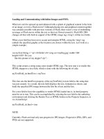
Daisy chaining allows multiple devices to share the
same clock and chip select line, freeing I/O pins on the
microcontroller. Figure 1 shows connections for three
devices. Note that the SO pin is connected to the SI pin
of the next device in the chain. It is not recommended
to use the single-channel MCP41XXX at the beginning
or middle of a daisy chain, because this device does
not have an SO pin. However, the MCP41XXX device
can be connected at the end of the chain as shown in
Figure 1. The waveforms in Figure 2 illustrates that
data will be clocked out of the SO pin on the falling
edge of the clock.
OVERVIEW
The MCP41XXX and MCP42XXX family of digital
potentiometers allow for daisy chaining of multiple
devices on a single SPI™ bus. It is possible to communicate to multiple devices using one 3-wire data bus
(CS, CLK and DATA), by connecting the SO pin on one
device to the SI pin of the next device in the chain. This
application note details one example of source code
that is used to communicate with eight daisy chained
devices.
CS
SCK
Microcontroller SO
CS
SCK
PIC16F876
FIGURE 1:
SI
CS
SCK
CS
SCK
SO
SI
SO
SI
Device 1
Device 2
Device 3
MCP42010
MCP42050
MCP41100
Connections For Daisy Chained Devices
Data Registers for all
devices are loaded
on rising edge of CS
CS
1 2 3 4 5 6 7 8 9 10 11 12 13 14 15 16
1 2 3 4 5 6 7 8 9 10 11 12 13 1415 16
1 2 3 4 5 6 7 8 9 10 11 12 13 14 15 16
SCK
Command Byte
for Device 3
SI
Data Byte
for Device 3
X X C C X X P P D D D D D D D D
First 16 bits shifted out
will always be zeros
Data Byte
for Device 2
Command Byte
for Device 1
Data Byte
for Device 1
X X C C X X P P D D D D D D D D
X X C C X X P P D D D D D D D D
Command and Data for Device 3
start shifting out after the first 16 clocks
Command and Data for Device 2
start shifting out after the first 32 clocks
X X C C X X P P D D D D D D D D
SO
FIGURE 2:
Command Byte
for Device 2
X X C C X X P P D D D D D D D D
Protocol For Daisy Chained Devices
SPI™ is a trademark of Motorola Inc.
2001 Microchip Technology Inc.
DS00747A-page 1
AN747
On power-up and the rising edge of Chip Select (CS),
the shift register of each device is automatically loaded
with zeros. Because of this, the first 16 bits that come
out of the SO pin after the CS line goes low will always
be zeros. Consequently, the first command that is
loaded into a device in the daisy chain will invoke a
NOP command into the next device in the chain. This
feature makes it necessary only to send command and
data bytes to the device farthest down the chain that
needs a new command. For example, if there are three
devices in a daisy chain and the device in the middle
(second device) requires an update, four bytes need to
be transmitted from the controller. The first two bytes
are the command and data bytes for the second device
and the last two bytes are the command and data bytes
for the first device. The first device does not need to be
updated, therefore, the command byte for this device
should be ’XX00XXXX’. The last device in the chain
will have a NOP loaded from the previous device so no
registers will be affected when the CS pin is raised to
execute the command. The user must always ensure
that multiples of 16 clock cycles are always provided
(while CS is low), otherwise, commands will be
ignored.
IMPLEMENTATION
Appendix A shows absolute assembly code communicating to the daisy chained devices. The communication is accomplished using the hardware SPI module.
The command and data bytes required by the digital
potentiometers are stored orderly in the program memory using a lookup table. The table order is formed so
that the device at the end of the chain (device 8) has its
command and data bytes at the top of the lookup table
as shown in Figure 3.
0x20
0x21
0x22
0x23
0x24
0x25
0x26
0x27
0x28
0x29
0x2A
0x2B
0x2C
0x2D
0x2E
0x2F
FIGURE 3:
Data
0x11
0xFF
0x12
0x80
0x13
0x40
0x21
0x00
0x22
0x00
0x13
0xFF
0x13
0x80
0x13
0x40
A call to the TRANSMIT routine transmits the content of
the W register to the digital potentiometer through SPI.
Then counter is incremented and the data byte fetching
and transmission routine repeats. After the completion
of the data byte transmission, the counter is incremented and checked for end-of-table.
The loop repeats for the next device (the seventh
device). Once the first device in the chain is programmed with the corresponding byte, transmission is
terminated by pulling Chip Select High. It is important
to note that Chip Select is not pulled high until the command and data bytes for all eight devices on the chain
have been transmitted.
MEMORY USAGE
This application uses a PIC16F876 to communicate
with eight MCP42XXX devices on a single daisy chain.
The MXDEV™ Analog/Mixed Signal Evaluation System hardware was used to test the code. The driver
board was connected to the MCP42XXX digital potentiometer evaluation board and the additional seven digital potentiometers were interfaced by hardwiring to a
breadboard.
Address
The source code initializes the Synchronous Serial Port
(SSP) module on the PIC16F876 device to communicate in the SPI mode. A counter is used as a pointer to
the program memory table. Initially, the counter is
cleared and communication is initiated by pulling chip
select low. Then the contents of the counter is transferred to the Working Register (W) and a call to the
TABLE is executed to fetch the first command byte
which is targeted to the 8th device. This command byte
is transferred to the W register upon return from the
call.
Command Byte
for Device 8
Data Byte
for Device 8
In the MCP41XXX/42XXX Digital Potentiometer, the
following memory was used:
Program Memory:
48 bytes
Data Memory:
0 bytes
EEPROM Memory:
0 bytes
REFERENCES
MCP41XXX/42XXX Single/Dual Digital Potentiometer
with SPI Interface, Microchip Technology Inc.,
DS11195, 2000.
KEYWORDS
1
Potentiometer
2
Digital Potentiometers
3
MCP4XXXX
4
MCP41XXX
5
MCP42XXX
6
SPI
7
Daisy chain
Command Byte
for Device 1
Data Byte
for Device 1
Potentiometer Data Structure In RAM
DS00747A-page 2
2001 Microchip Technology Inc.
AN747
Software License Agreement
The software supplied herewith by Microchip Technology Incorporated (the “Company”) for its PICmicro® Microcontroller is intended
and supplied to you, the Company’s customer, for use solely and exclusively on Microchip PICmicro Microcontroller products.
The software is owned by the Company and/or its supplier, and is protected under applicable copyright laws. All rights are reserved.
Any use in violation of the foregoing restrictions may subject the user to criminal sanctions under applicable laws, as well as to civil
liability for the breach of the terms and conditions of this license.
THIS SOFTWARE IS PROVIDED IN AN “AS IS” CONDITION. NO WARRANTIES, WHETHER EXPRESS, IMPLIED OR STATUTORY, INCLUDING, BUT NOT LIMITED TO, IMPLIED WARRANTIES OF MERCHANTABILITY AND FITNESS FOR A PARTICULAR PURPOSE APPLY TO THIS SOFTWARE. THE COMPANY SHALL NOT, IN ANY CIRCUMSTANCES, BE LIABLE FOR
SPECIAL, INCIDENTAL OR CONSEQUENTIAL DAMAGES, FOR ANY REASON WHATSOEVER.
APPENDIX A:
SOURCE CODE FOR COMMUNICATING WITH DAISY CHAINED
DEVICES
;*******************************************************************************************
;
;
COMMUNICATING WITH EIGHT DAISY CHAINED MCP42XXX DIGITAL POTENTIOMETERS
;
;
- THIS PROGRAM IS ABSOLUTE ASSEMBLY USING THE HARDWARE
;
SPI MODULE TO PROGRAM THE DIGITAL POTENTIOMETERS
;
;*******************************************************************************************
;
;
;
Filename:
MCP42_Dzy.ASM
;
Date:
01.30.2001
;
File Version:
1.00
;
;
Assembler:
MPASM
VERSION 2.50
;
;
PROGRAMER:
PRO MATE DEVICE PROGRAMMER, VERSION 5.30.00
;
;
File Required:
PIC16F876.inc
;
;
Author:
Ezana Haile/Craig L. King
;
Company:
Microchip Technology Incorporated
;
;
;*******************************************************************************************
;
;
;
This code demonstrates how to communicate to daisy-chained MCP42xxx digital
;
potentiometers. The potentiometers require a serial communication to program
;
the command byte and the data byte. This MCU (PIC16F876) has a built-in
;
Serial Peripheral Interface (SPI) which can be used to program the Pot
;
effectively. There are eight daisy-chained digital Pots. This code programs
;
all at once and terminates. User would have to change the command and data
;
bytes from the table below and reprogarm the MCU.
;
;
;*******************************************************************************************
*
*
*
*
*
*
*
*
*
*
*
*
*
*
*
*
*
*
*
*
*
*
*
*
*
*
*
*
*
*
*
*
*
#include
ERRORLEVEL -302
__CONFIG _BODEN_OFF & _PWRTE_OFF & _CP_OFF & _WDT_OFF & _XT_OSC
2001 Microchip Technology Inc.
DS00747A-page 3
AN747
;*******************************************************************************************
;******************** EQUATES ************************************************************
;*******************************************************************************************
CS
EQU
H’00’
;CHIP SELECT PIN
COUNTER
RES
1
;COUNTER
;*******************************************************************************************
;******************** PROGRAM ORIGIN *****************************************************
;*******************************************************************************************
ORG
0X00
;------------------------------------------------------------------------------------------;-------------------- PORTB AND SPI SETTING ---------------------------------------------;-------------------------------------------------------------------------------------------
BSF
MOVLW
MOVWF
MOVWF
BCF
STATUS, RP0
H’00’
TRISA
TRISC
STATUS, RP0
;SPECIFY BANK 1
;SET PORTA AS AN OUTPUT
;SET PORTC AS AN OUTPUT
;SPECIFY BANK 0
CLRF
CLRF
MOVLW
MOVWF
PCLATH
INTCON
0x30
SSPCON
;ENSURE PCLATH BIT 3 IS CLEARED
;ENSURE ALL INTERRUPTS ARE DISABLED
;
;SET SYNC SERIAL PORT CONTROL REGISTER
;------------------------------------------------------------------------------------------;---------------------- PROGRAM ALL POTs USING LOOKUP TABLE ------------------------------;-------------------------------------------------------------------------------------------
LOOP
DS00747A-page 4
CLRF
COUNTER
;SET THE COUNTER
BCF
PORTA, CS
;INITIATE COMMUNICATION
MOVF
CALL
CALL
COUNTER,W
TABLE
TRANSMIT
;FETCH BYTE FROM THE LOOKUP TABLE
;TRANSMIT THE COMMAND BYTE
INCF
COUNTER,F
;INCREMENT COUTNER
MOVF
CALL
CALL
COUNTER,W
TABLE
TRANSMIT
;TRANSMIT THE RESISTANCE VALUE
INCF
BTFSS
GOTO
COUNTER,F
COUNTER,4
LOOP
;TEST FOR COMPLETION (END-OF-TABLE)
BSF
GOTO
PORTA, CS
FINISH
;TERMINATE COMMUNICATION
;FINISH
2001 Microchip Technology Inc.
AN747
;------------------------------------------------------------------------------------------;---------------------------------- LOOKUP TABLE ----------------------------------------;-------------------------------------------------------------------------------------------
TABLE
ADDWF
retlw
retlw
retlw
retlw
retlw
retlw
retlw
retlw
retlw
retlw
retlw
retlw
retlw
retlw
retlw
retlw
PCL,1
0x11
0XFF
0x12
0x80
0x13
0x40
0x21
0x00
0x22
0x00
0x13
0xFF
0x13
0x80
0x13
0x40
;
;
;
;
;
;
;
;
;
;
;
;
;
;
;
;
;
Add the offset on the program counter
Command Byte for Device 8 - Write P0
Data Byte for Device 8
Command Byte for Device 7 - Write P1
Data Byte for Device 7
Command Byte for Device 6 - Write P0 and
Data Byte for Device 6
Command Byte for Device 5 - Shutdown P0
Data Byte for Device 5
Command Byte for Device 4 - Shutdown P1
Data Byte for Device 4
Command Byte for Device 3 - Write P0 and
Data Byte for Device 3
Command Byte for Device 2 - Write P0 and
Data Byte for Device 2
Command Byte for Device 1 - Write P0 and
Data Byte for Device 1
P1
P1
P1
P1
;------------------------------------------------------------------------------------------;---------------------------- TRANSMISSION SUBROUTINE -----------------------------------;-------------------------------------------------------------------------------------------
TRANSMIT
WAIT
BCF
MOVWF
STATUS, RP0
SSPBUF
;SPECIFY BANK 0
;PLACE DATA IN BUFFER TO SEND
BSF
BTFSS
GOTO
BCF
STATUS, RP0
SSPSTAT, BF
WAIT
STATUS, RP0
;SPECIFY BANK 1
;CHECK IF TRANSMISSION IS COMPLETE
;
;SPECIFY BANK 0
RETURN
;RETURN FROM SUBROUTINE
;*******************************************************************************************
FINISH
GOTO
FINISH
END
;********************
END OF PROGRAM
2001 Microchip Technology Inc.
*****************************************************
DS00747A-page 5
AN747
NOTES:
DS00747A-page 6
2001 Microchip Technology Inc.
AN747
“All rights reserved. Copyright © 2001, Microchip
Technology Incorporated, USA. Information contained
in this publication regarding device applications and the
like is intended through suggestion only and may be
superseded by updates. No representation or warranty
is given and no liability is assumed by Microchip
Technology Incorporated with respect to the accuracy
or use of such information, or infringement of patents or
other intellectual property rights arising from such use
or otherwise. Use of Microchip’s products as critical
components in life support systems is not authorized
except with express written approval by Microchip. No
licenses are conveyed, implicitly or otherwise, under
any intellectual property rights. The Microchip logo and
name are registered trademarks of Microchip
Technology Inc. in the U.S.A. and other countries. All
rights reserved. All other trademarks mentioned herein
are the property of their respective companies. No
licenses are conveyed, implicitly or otherwise, under
any intellectual property rights.”
Trademarks
The Microchip name, logo, PIC, PICmicro,
PICMASTER, PICSTART, PRO MATE, KEELOQ,
SEEVAL, MPLAB and The Embedded Control
Solutions Company are registered trademarks of
Microchip Technology Incorporated in the U.S.A. and
other countries.
Total Endurance, ICSP, In-Circuit Serial Programming,
FilterLab, MXDEV, microID, FlexROM, fuzzyLAB,
MPASM, MPLINK, MPLIB, PICDEM, ICEPIC,
Migratable Memory, FanSense, ECONOMONITOR,
SelectMode and microPort are trademarks of
Microchip Technology Incorporated in the U.S.A.
Serialized Quick Term Programming (SQTP) is a
service mark of Microchip Technology Incorporated in
the U.S.A.
All other trademarks mentioned herein are property of
their respective companies.
© 2001, Microchip Technology Incorporated, Printed in
the U.S.A., All Rights Reserved.
Microchip received QS-9000 quality system
certification for its worldwide headquarters,
design and wafer fabrication facilities in
Chandler and Tempe, Arizona in July 1999. The
Company’s quality system processes and
procedures are QS-9000 compliant for its
PICmicro® 8-bit MCUs, KEELOQ® code hopping
devices, Serial EEPROMs and microperipheral
products. In addition, Microchip’s quality
system for the design and manufacture of
development systems is ISO 9001 certified.
2001 Microchip Technology Inc.
DS00747A-page 7
M
WORLDWIDE SALES AND SERVICE
AMERICAS
New York
Corporate Office
150 Motor Parkway, Suite 202
Hauppauge, NY 11788
Tel: 631-273-5305 Fax: 631-273-5335
2355 West Chandler Blvd.
Chandler, AZ 85224-6199
Tel: 480-792-7200 Fax: 480-792-7277
Technical Support: 480-792-7627
Web Address:
Rocky Mountain
2355 West Chandler Blvd.
Chandler, AZ 85224-6199
Tel: 480-792-7966 Fax: 480-792-7456
Atlanta
500 Sugar Mill Road, Suite 200B
Atlanta, GA 30350
Tel: 770-640-0034 Fax: 770-640-0307
Austin
Analog Product Sales
8303 MoPac Expressway North
Suite A-201
Austin, TX 78759
Tel: 512-345-2030 Fax: 512-345-6085
Boston
2 Lan Drive, Suite 120
Westford, MA 01886
Tel: 978-692-3848 Fax: 978-692-3821
Boston
Analog Product Sales
Unit A-8-1 Millbrook Tarry Condominium
97 Lowell Road
Concord, MA 01742
Tel: 978-371-6400 Fax: 978-371-0050
Chicago
333 Pierce Road, Suite 180
Itasca, IL 60143
Tel: 630-285-0071 Fax: 630-285-0075
Dallas
4570 Westgrove Drive, Suite 160
Addison, TX 75001
Tel: 972-818-7423 Fax: 972-818-2924
Dayton
Two Prestige Place, Suite 130
Miamisburg, OH 45342
Tel: 937-291-1654 Fax: 937-291-9175
Detroit
Tri-Atria Office Building
32255 Northwestern Highway, Suite 190
Farmington Hills, MI 48334
Tel: 248-538-2250 Fax: 248-538-2260
Los Angeles
18201 Von Karman, Suite 1090
Irvine, CA 92612
Tel: 949-263-1888 Fax: 949-263-1338
Mountain View
Analog Product Sales
1300 Terra Bella Avenue
Mountain View, CA 94043-1836
Tel: 650-968-9241 Fax: 650-967-1590
ASIA/PACIFIC (continued)
Korea
Microchip Technology Korea
168-1, Youngbo Bldg. 3 Floor
Samsung-Dong, Kangnam-Ku
Seoul, Korea
Tel: 82-2-554-7200 Fax: 82-2-558-5934
San Jose
Microchip Technology Inc.
2107 North First Street, Suite 590
San Jose, CA 95131
Tel: 408-436-7950 Fax: 408-436-7955
Singapore
Microchip Technology Singapore Pte Ltd.
200 Middle Road
#07-02 Prime Centre
Singapore, 188980
Tel: 65-334-8870 Fax: 65-334-8850
Toronto
6285 Northam Drive, Suite 108
Mississauga, Ontario L4V 1X5, Canada
Tel: 905-673-0699 Fax: 905-673-6509
Taiwan
Microchip Technology Taiwan
11F-3, No. 207
Tung Hua North Road
Taipei, 105, Taiwan
Tel: 886-2-2717-7175 Fax: 886-2-2545-0139
ASIA/PACIFIC
Australia
Microchip Technology Australia Pty Ltd
Suite 22, 41 Rawson Street
Epping 2121, NSW
Australia
Tel: 61-2-9868-6733 Fax: 61-2-9868-6755
EUROPE
China - Beijing
Denmark
Microchip Technology Beijing Office
Unit 915
New China Hong Kong Manhattan Bldg.
No. 6 Chaoyangmen Beidajie
Beijing, 100027, No. China
Tel: 86-10-85282100 Fax: 86-10-85282104
Microchip Technology Denmark ApS
Regus Business Centre
Lautrup hoj 1-3
Ballerup DK-2750 Denmark
Tel: 45 4420 9895 Fax: 45 4420 9910
France
China - Shanghai
Microchip Technology Shanghai Office
Room 701, Bldg. B
Far East International Plaza
No. 317 Xian Xia Road
Shanghai, 200051
Tel: 86-21-6275-5700 Fax: 86-21-6275-5060
Hong Kong
Microchip Asia Pacific
RM 2101, Tower 2, Metroplaza
223 Hing Fong Road
Kwai Fong, N.T., Hong Kong
Tel: 852-2401-1200 Fax: 852-2401-3431
India
Microchip Technology Inc.
India Liaison Office
Divyasree Chambers
1 Floor, Wing A (A3/A4)
No. 11, O’Shaugnessey Road
Bangalore, 560 025, India
Tel: 91-80-2290061 Fax: 91-80-2290062
Japan
Microchip Technology Intl. Inc.
Benex S-1 6F
3-18-20, Shinyokohama
Kohoku-Ku, Yokohama-shi
Kanagawa, 222-0033, Japan
Tel: 81-45-471- 6166 Fax: 81-45-471-6122
Arizona Microchip Technology SARL
Parc d’Activite du Moulin de Massy
43 Rue du Saule Trapu
Batiment A - ler Etage
91300 Massy, France
Tel: 33-1-69-53-63-20 Fax: 33-1-69-30-90-79
Germany
Arizona Microchip Technology GmbH
Gustav-Heinemann Ring 125
D-81739 Munich, Germany
Tel: 49-89-627-144 0 Fax: 49-89-627-144-44
Germany
Analog Product Sales
Lochhamer Strasse 13
D-82152 Martinsried, Germany
Tel: 49-89-895650-0 Fax: 49-89-895650-22
Italy
Arizona Microchip Technology SRL
Centro Direzionale Colleoni
Palazzo Taurus 1 V. Le Colleoni 1
20041 Agrate Brianza
Milan, Italy
Tel: 39-039-65791-1 Fax: 39-039-6899883
United Kingdom
Arizona Microchip Technology Ltd.
505 Eskdale Road
Winnersh Triangle
Wokingham
Berkshire, England RG41 5TU
Tel: 44 118 921 5869 Fax: 44-118 921-5820
01/30/01
All rights reserved. © 2001 Microchip Technology Incorporated. Printed in the USA. 3/01
Printed on recycled paper.
Information contained in this publication regarding device applications and the like is intended through suggestion only and may be superseded by
updates. It is your responsibility to ensure that your application meets with your specifications. No representation or warranty is given and no liability is
assumed by Microchip Technology Incorporated with respect to the accuracy or use of such information, or infringement of patents or other intellectual
property rights arising from such use or otherwise. Use of Microchip’s products as critical components in life support systems is not authorized except with
express written approval by Microchip. No licenses are conveyed, implicitly or otherwise, except as maybe explicitly expressed herein, under any intellectual property rights. The Microchip logo and name are registered trademarks of Microchip Technology Inc. in the U.S.A. and other countries. All rights
reserved. All other trademarks mentioned herein are the property of their respective companies.
DS00747A-page 8
2001 Microchip Technology Inc.