AN0774 asynchronous communications with the PICmicro® USART
Bạn đang xem bản rút gọn của tài liệu. Xem và tải ngay bản đầy đủ của tài liệu tại đây (522.63 KB, 28 trang )
AN774
Asynchronous Communications with the PICmicro® USART
Author:
Mike Garbutt
Microchip Technology Inc.
INTRODUCTION
Many PICmicro® microcontroller devices have a builtin USART and it is one of the most commonly used
serial interface peripherals. It is also known as the
Serial Communications Interface, or SCI. The most
common use of the USART is to communicate to a PC
serial port using the RS-232 protocol. It has a variety of
other uses however, as we will discuss in this Application Note.
USART stands for Universal Synchronous Asynchronous Receiver Transmitter and its main function is to
transmit or receive serial data. Its operation can be
divided into two broad categories: synchronous and
asynchronous. Synchronous operation uses a clock
and data line while asynchronous operation has no
separate clock accompanying the data. There are substantial differences between these two modes of operation and this Application Note is concerned only with
asynchronous operation.
In addition to asynchronous operation, this Application
Note describes:
• Controlling the baud rate or speed of communication
• Detecting and handling errors
• Using interrupts to improve speed and efficiency
A discussion of the RS-232, RS-422 and RS-485 protocols and use of the USART with these communication protocols is also included.
The purpose of this Application Note is to explain the
various ways that the USART can be used in the Asynchronous mode and the issues involved in implementing code that uses the USART.
Note:
This Application Note is not meant to be a
detailed technical description of the
USART. That information is contained in
the Data Sheets for the parts containing a
USART and in the Reference Manuals
(see references at the end of this document).
OVERVIEW
The USART can transmit and receive data serially. It
can transfer a frame of data with eight or nine data bits
per transmission and detect errors when data is overwritten or incorrectly framed. It can generate interrupts
when a reception occurs (or a transmission completes)
and it contains data buffers that simplify the timing
requirements of the software controlling the USART.
Some parts have an addressable USART that uses the
ninth data bit to distinguish between address and data
receptions. This allows simple filtering of incoming data
and is often used in the RS-485 protocol.
PICMICRO MICROCONTROLLER FAMILIES
The USART is incorporated into many PIC16, PIC17
and PIC18 parts. The USARTs in all these parts are
basically the same, but there are some important differences to consider:
• The USART is addressable in all current PIC18
parts and is not addressable in all PIC17 parts.
The USART is addressable in some PIC16 parts
and is not addressable in other PIC16 parts.
• The USART in PIC17 parts does not have a high
speed baud rate option, while the USART in all
PIC16 and PIC18 parts does have a high speed
baud rate option.
• Most devices with a USART have only one. The
PIC17C7XX and some PIC18FXX20 parts have
two USARTs. Future PIC18 parts may have two
USARTs.
• The various families have different interrupt control registers and the PIC18 parts allow the interrupts to be prioritized.
• Some new PIC18 parts have an enhanced
USART with added features not covered in this
application note.
SPECIAL FUNCTION REGISTERS
Several special function registers control the USART.
These registers allow the various modes of operation to
be selected, the baud rate (i.e., bit rate) to be set up,
data to be transferred, the transmit and receive status
to be monitored, etc. The registers that affect the
USART are shown in the following tables.
Numerous code examples are provided in Appendix A,
B and C to complement the text of this Application
Note. These examples are provided for PIC16, PIC17
and PIC18 devices separately.
2003 Microchip Technology Inc.
DS00774A-page 1
AN774
TABLE 1:
REGISTERS THAT CONTROL
TRANSMISSION AND
RECEPTION
Register Name
Description
TABLE 4:
INTERRUPT REGISTERS FOR
PIC16 DEVICES
Register
Name
Description
TXSTA
Transmit Status and Control
INTCON
RCSTA
Receive Status and Control
PIR1
Peripheral Interrupt Flag Register
PIE1
Peripheral Interrupt Enable Register
The TXSTA and RCSTA registers are used to control
transmission and reception but there are some overlapping functions and both registers are always used.
Parts with two USARTs have TXSTA1, RCSTA1,
TXSTA2 and RCSTA2 registers instead of a single pair
of TXSTA and RCSTA registers.
TABLE 2:
REGISTERS USED TO WRITE
AND READ DATA
Register Name
Description
TXREG
Transmit Data Register
RCREG
Receive Data Register
The TXREG and RCREG registers are used to write
data to be transmitted and to read the received data.
Parts with two USARTs have TXREG1, RCREG1,
TXREG2 and RCREG2 registers instead of a single
pair of TXREG and RCREG registers.
TABLE 3:
REGISTER FOR SETTING
BAUD RATE
Register Name
SPBRG
Description
INTERRUPT REGISTERS FOR
PIC17 DEVICES
Register
Name
CPUSTA
Description
CPU Status Register
INTSTA
Interrupt Status Register
PIE1, PIE2
Peripheral Interrupt Enable Register
PIR1, PIR2
Peripheral Interrupt Flag Register
TABLE 6:
INTERRUPT REGISTERS FOR
PIC18 DEVICES
Register
Name
INTCON
Description
Interrupt Control Register
RCON
RESET Control Register
PIE1, PIE3
Peripheral Interrupt Enable Registers
PIR1, PIR3
Peripheral Interrupt Flag Registers
IPR1, IPR3
Peripheral Interrupt Priority Registers
Baud Rate Generator
The SPBRG register allows the baud rate to be set.
Parts with two USARTs have SPBRG1 and SPBRG2
registers instead of a single SPBRG register.
In addition, there are interrupt registers that control the
interrupts but are also used to determine whether data
has been received or can be transmitted. Interrupts are
often used when the PICmicro MCU processor is busy
executing code and data needs to be transmitted or
received in the background. Since the interrupts differ
between the different processor architectures, please
see the section on Interrupts in this Application Note for
more details.
Interrupt registers for different PICmicro devices are
shown in Tables 4, 5 and 6.
DS00774A-page 2
TABLE 5:
Interrupt Control Register
EMULATOR ISSUES
Most emulators and debuggers for PICmicro devices
support the USART peripheral. However, it is important
for the user to carefully study the limitations of the specific emulator or debugger being used.
Problems may arise when halting or single-stepping.
Interrupts may not function as expected if they occur
while halted or single-stepping. In addition, if the emulator or debugger reads RCREG to update a watch window or other view, this may cause RCIF to be cleared
and received data to be missed by the code.
ASYNCHRONOUS OPERATION
The USART uses two I/O pins to transmit and receive
serial data. Because there is no separate clock signal
for asynchronous operation, one pin (TX) is used for
transmission and the other pin (RX) is used for reception. Both transmission and reception can occur at the
same time and this is known as ‘full duplex’ operation.
Transmission and reception can be independently
enabled, but when the serial port is enabled the
USART will control both pins, and one cannot be used
for general purpose I/O when the other is being used
for transmission or reception.
2003 Microchip Technology Inc.
AN774
SIGNALS
Since there is no separate clock in asynchronous operation, the receiver needs a method of synchronizing
with the transmitter. This is achieved by having a fixed
baud rate and by using START and STOP bits. A typical
Asynchronous mode signal is shown in Figure 1.
D1
D2
D3
D4
D5
D6
D7
1
0
1
0
0
1
0
0
The USART outputs and inputs logic level signals on
the TX and RX pins of the PICmicro MCU. The signal
is high when no transmission (or reception) is in
progress and goes low when the transmission starts.
The receiving device uses this low-going transition to
determine the timing for the bits that follow.
The signal stays low for the duration of the START bit,
and is followed by the data bits, Least Significant bit
first. The USART can transmit and receive either eight
or nine data bits. The STOP bit follows the last data bit
and is always high. The transmission therefore ends
with the pin high. After the STOP bit has completed, the
START bit of the next transmission can occur as shown
by the dotted lines.
There are several things to note about the waveform in
Figure 1, which represents the signal on the TX or RX
pins of the microcontroller. The START bit is a ‘zero’
and the STOP bit is a ‘one.’ The data is sent Least Significant bit first, so the bit pattern looks backwards in
comparison to the way it appears when written as a
FIGURE 2:
STOP bit
D0
ASYNCHRONOUS MODE SIGNAL
START bit
FIGURE 1:
binary number. The data is not inverted, even though
RS-232 uses negative voltages to represent a logic
one. Generally, when using the USART for RS-232
communications, the signals must be inverted and
level-shifted through a transceiver chip of some sort.
There are some features and uses of the USART that
affect the signal. The Nine-bit mode is useful when parity or an extra STOP bit is needed. It can also be used
for the Addressable mode described later in this Application Note. To implement parity, the ninth bit is set to
make the total number of data bits either even or odd,
depending on whether even or odd parity is being used.
If two STOP bits are needed, the ninth data bit is set to
one so that the signal stays high for two-bit periods
after the first eight data bits.
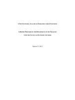
TRANSMISSION
A simplified block diagram of the USART asynchronous transmission logic is shown in Figure 2.
ASYNCHRONOUS TRANSMISSION
TX9D
TXREG
1-bit
8 bits
TX9=1
TRMT=1
when empty
Transmit Shift Register
The USART can be configured to transmit eight or nine
data bits by the TX9 bit in the TXSTA register. If nine
bits are to be transmitted, the ninth data bit must be
placed in the TX9D bit of the TXSTA register before
writing the other eight bits to the TXREG register. Once
2003 Microchip Technology Inc.
TXIF=1
when empty
TX Pin
data has been written to TXREG, the eight or nine bits
are moved into the Transmit Shift Register. From there
they are clocked out onto the TX pin preceded by a
START bit and followed by a STOP bit.
DS00774A-page 3
AN774
Note:
When TXREG has been written, TXREG
and the TX9D bit could immediately be
transferred into the Transmit Shift Register,
if it is empty, so TX9D must be written
before writing TXREG.
The use of a separate Transmit Shift Register allows
new data to be written to the TXREG register while the
previous data is still being transmitted. This allows the
maximum throughput to be achieved.
The TXIF bit in the PIR1 register indicates when data
can be written to TXREG and will cause an interrupt if
the interrupt is enabled. This means that if there is no
more data to transmit, the interrupt should be disabled;
otherwise, the interrupt routine will keep getting called.
Note:
Once the data in the Transmit Shift Register has been
clocked out on the TX pin, the TRMT bit in the TXSTA
register will be set. This occurs at the beginning of the
STOP bit. In cases where the USART is to be turned off
between transmissions, it is important to use the TRMT
bit to determine when the transmission has completed
and it may also be necessary to ensure that the STOP
bit is given time to complete.
There is a delay of one instruction cycle after writing to
TXREG, before TXIF gets cleared. The user needs to
be aware of this characteristic because if TXIF is tested
immediately after writing to TXREG, unexpected results
can occur. Consider the following code:
The TXIF bit does not indicate that the
transmission has completed. It will be set
when data is moved from TXREG into the
Transmit Shift Register.
EXAMPLE 1:
TXIF One Cycle Clearing Delay Problem
movlw
movwf
btfss
goto
movlw
movwf
btfss
goto
movlw
movwf
btfss
goto
'A'
TXREG
PIR1,TXIF
$-1
'B'
TXREG
PIR1,TXIF
$-1
'C'
TXREG
PIR1,TXIF
$-1
;load
;into
;test
;wait
;load
;into
;test
;wait
;load
;into
;test
;wait
'A'
TXREG
if TXREG empty
until TXREG empty
'B'
TXREG
if TXREG empty - will skip
until TXREG empty
'C'
TXREG
if TXREG empty
until TXREG empty
If the USART is idle when this code starts, the characters ‘AC’ will be transmitted. Writing 'A' to TXREG will
result in this data being passed through to the transmit
shift register and TXIF will remain set, indicating that
TXREG is still empty. Writing 'B' to TXREG will result in
TXIF being cleared after one instruction cycle, indicating that TXREG is full. However, since the code tests
the TXIF flag immediately following the write to TXREG,
it will still see the flag set high and will execute the code
that writes 'C' to TXREG, overwriting the 'B' already in
TXREG. So this code transmits 'AC' instead of the
'ABC' expected.
Note:
The user needs to ensure that the TXIF
flag is never tested immediately following a
write to TXREG. If necessary, ‘NOP’ instructions can be inserted but simply rearranging the code is usually sufficient.
DS00774A-page 4
2003 Microchip Technology Inc.
AN774
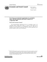
RECEPTION
A simplified block diagram of the USART asynchronous reception logic is shown in Figure 3.
FIGURE 3:
ASYNCHRONOUS RECEPTION
RX Pin
Receive Shift Register
1 bit
8 bits
FIFO
Buffer
RX9=1
RX9D
RCREG
RCIF=1
when full
The USART can be configured to receive eight or nine
bits by the RX9 bit in the RCSTA register. After the
detection of a START bit, eight or nine bits of serial data
are shifted from the RX pin into the Receive Shift Register, one bit at a time. After the last bit has been shifted
in, the STOP bit is checked and the data is moved into
the FIFO (First In First Out) buffer. RCREG is the output
of a two element FIFO buffer. If another byte is received
before the first byte has been read from RCREG, it will
be kept in the FIFO ‘behind’ RCREG until the first byte
has been read. If nine-bit reception is enabled, the
ninth bit is passed into the RX9D bit in the RCSTA register in the same way as the other eight bits of data are
passed into the RCREG register.
Two bytes can be held in the FIFO while a third is being
received. The user must ensure that data is read from
RCREG before the third byte has been completely
shifted in, otherwise the third byte will be discarded and
an overrun error will be indicated.
Note:
When RCREG has been read, RCREG
and the RX9D bit can immediately be overwritten with the next byte in the FIFO, so
RX9D must be read before reading
RCREG.
received, the RCIF bit will remain set until all the data
has been read from RCREG. When using interrupts,
this means that the interrupt routine can read one byte
at a time and interrupts will keep occurring until all the
data has been read.
ADDRESSABLE MODE
Some devices have an addressable USART that can
automatically filter certain transmissions. The received
bytes are separated into two categories for addresses
and data, indicated by the ninth data bit as shown in
Figure 4. Only address bytes are processed by the
USART, all other data is ignored. This feature is usually
used when there are multiple devices on a bus and
transmissions are addressed to a particular device.
The receiving devices ignore all data bytes with the
ninth bit low and only receive address bytes with the
ninth bit set. When the address byte is received and
matches its own address, the receiving device can
change into the normal Reception mode to receive the
data that follows the address byte. Nine-bit transmission and reception is always used with the addressable
USART feature.
The use of a separate receive shift register and a FIFO
buffer allows time for the software running on the PICmicro MCU to read out the received data before an
overrun error occurs. It is possible to have received two
bytes and be busy receiving a third byte before the data
in the RCREG register is read. This reduces the timing
burden on the code that reads the data.
The RCIF bit in the PIR1 register indicates when data
is available in the RCREG and will cause an interrupt if
the interrupt is enabled. If two bytes have been
2003 Microchip Technology Inc.
DS00774A-page 5
AN774
FIGURE 4:
ADDRESSABLE MODE
RX Pin
Receive Shift Register
Test
ADDEN=1
RX9=1
Load only if set
1-bit
8 bits
Buffer
RX9D
FIFO
RCREG
RCIF=1
when full
BAUD RATE
Baud rate refers to the speed at which the serial data is
transferred, in bits per second. In Asynchronous mode,
the baud rate generator sets the baud rate using the
value in the SPBRG register. The BRGH bit in TXSTA
selects between high and low speed options for greater
flexibility in setting the baud rate, as shown in Table 7.
ing the actual baud rate using the nearest integer value
of SPBRG, the error can be determined. Whether this
error is acceptable usually depends on the application.
As an example of a baud rate calculation, consider the
case of a microcontroller operating at 4 MHz that is
required to communicate at 9600 baud with a serial
port on a PC.
Example calculation:
TABLE 7:
FORMULAS FOR BAUD RATE
Baud Rate
Speed Option
FOSC/(16(SPBRG+1))
BRGH=1 - High speed
FOSC/(64(SPBRG+1))
BRGH=0 - Low speed
4 MHz oscillator, 9600 baud
For BRGH = 1
SPBRG = 4000000/(16 x 9600) - 1 = 25.04
For BRGH = 0
SPBRG = 4000000/(64 x 9600) - 1 = 5.51
These formulas show how the baud rate is set by the
value in the SPBRG register and BRGH bit. It is more
important for the user to be able to calculate the value
to place in the SPBRG register to achieve a desired
baud rate. The formulas shown in Table 8 can be used
to perform this calculation.
TABLE 8:
FORMULAS FOR SPBRG
SPBRG Value
Speed Option
(FOSC/(16 x Baud rate)) -1
BRGH=1 - High speed
(FOSC/(64 x Baud rate)) - 1
BRGH=0 - Low speed
The SPBRG register can have a value of zero to 255
and must always be an integer value. When these formulas yield a value for SPBRG that is not an integer,
there will be a difference between the desired baud rate
and the rate that can actually be achieved. By calculat-
DS00774A-page 6
Best choice is BRGH = 1, SPBRG = 25
When BRGH is set to zero, the ideal value of SPBRG
is calculated as 5.51. Since this differs from the closest
integer value of six by approximately nine percent, this
will cause a corresponding error in the baud rate.
When BRGH is set to one, the ideal value of SPBRG is
calculated as 25.04. This is very close to the integer
value of 25, which must be used. Setting SPBRG to 25
will give a baud rate of 9615 that is within two tenths of
a percent of the desired baud rate
An accurate and stable oscillator is required to get an
accurate and stable baud rate. A crystal or ceramic resonator works well, but an external RC oscillator is seldom accurate enough for reliable asynchronous
communications. It is not advisable to use an external
RC oscillator when doing RS-232 communications to a
PC, for example. The internal RC oscillator in some
parts is accurate enough to be used.
2003 Microchip Technology Inc.
AN774
There is an exception to the requirement for an accurate oscillator when some alternate method is used to
calibrate the baud rate for each transmission. For
example, if known data is received at a known baud
rate, it is possible to write software that will time the
incoming signal and calculate a suitable SPBRG value
to use. This technique is sometimes referred to as
‘autobaud’ and will not be covered in this Application
Note. Please refer to AN851 “A FLASH Bootloader for
PIC16 and PIC18 Devices” for an example of autobaud.
RS-232, RS-422, and RS-485 Interfaces
The three most common asynchronous communications interfaces used with the USART are:
• RS-232
• RS-422
• RS-485.
Many personal computers have one or more COM
ports that use the RS-232 interface, and it is common
to use this interface to communicate with a PICmicro
device using the USART.
The basic features of these interfaces are:
• RS-232 uses a single ended signal to indicate the
data.
• RS-422 and RS-485 use differential signals.
• RS-232 and RS-422 are used between two
devices.
• RS-485 is used for multiple devices on a bus.
RS-232 CHARACTERISTICS
RS-232 uses a single ended signal (referenced to
ground) to indicate the data. Typically, there is a ground
reference (GND) and two signals, a transmit (TXD) output and a receive (RXD) input. There are also other signals that may be used, including hardware
handshaking signals.
Generally, a positive voltage (greater than +5 VDC) represents ‘zero’ and a negative voltage (less than -5 VDC)
represents ‘one.’ The simplest bi-directional RS-232
system has two wires as shown in Figure 5. Transceivers are usually used to convert between the logic levels
of a microcontroller and the RS-232 voltage levels.
FIGURE 5:
TYPICAL RS-232
CONNECTION
Transmit
Receive
Receive
Transmit
2003 Microchip Technology Inc.
RS-232 IMPLEMENTATION
The program code required to perform RS-232 communications can be simple, since the USART typically
transmits and receives data in the form of bytes. The
code needs to detect whether data has been received
or can be transmitted and can then read or write a register to get or send the data. No signals need to be
enabled or disabled. RS-232 software can be more
complicated if the data format changes; for example, if
a parity bit or multiple STOP bits are used, or if hardware flow control is required. These issues are
described later in this Application Note.
A special symbol defined in the RS-232 interface is the
break signal. The break is a zero output that is maintained for some period longer than a single transmission. It is usually used to indicate or request a special
event such as indicating a problem, causing an interruption, hanging up a modem, etc. The USART has no
inherent way to generate or detect a break, but it can
be done.
To transmit a break, the baud rate generator can be set
to a lower baud rate for a single transmission of a zero
byte. The length of a break is not defined and it is typically in the order of 100 ms to 500 ms, although anything longer than a single transmission time is valid.
Because of the temporary baud rate change, the
USART will not be able to receive data correctly while
transmitting the break. Before changing baud rates to
send a break, the TRMT bit should be checked to
ensure that the last transmission was completed.
When receiving a break, the first indication that a break
condition exists is that a framing error has been
detected. This is because when the STOP bit is
expected to be a one, the break will keep the signal at
zero. Receiving data of zero with a framing error is usually sufficient to conclude that a break has occurred.
RS-422 CHARACTERISTICS
RS-422 uses differential signals, so there are two voltage signals to indicate the data by their relative voltages. Typically, the RS-422 signals include:
• A ground reference (GND)
• A pair of signals (A and B) for the data being
transmitted
• Another pair (A and B) for the data being received
Generally, when A is high and B is low, this represents
‘zero’ and when A is low and B is high, this represents
‘one.’ A typical bi-directional RS-422 system has four
wires as shown in Figure 6. Transceivers are usually
used to convert between the data signals of a microcontroller and the RS-422 differential voltage levels.
DS00774A-page 7
AN774
FIGURE 6:
TYPICAL RS-422 FOUR-WIRE
CONNECTION
Transmit
nals at the microcontroller are the same. RS-422 converters can be used between RS-232 devices for
transmission over longer distances.
RS-485 CHARACTERISTICS
Receive
Receive
Like RS-422, RS-485 also uses differential signals, so
there are two voltage signals to indicate the data by
their relative voltages. RS-485 outputs can be tri-stated
to allow multiple devices to transmit on the same pair of
signals, but otherwise they are electrically the same as
RS-422 signals. A master/slave arrangement is most
common for RS-485 systems and this can be implemented with one (see Figure 8) or two (see Figure 7)
pair(s) of wires. All devices can communicate over the
single pair of wires, or the master device can transmit
on a separate pair of wires which simplifies the management of the traffic on the bus.
Transmit
RS-422 IMPLEMENTATION
Code for RS-422 applications is no different from RS232 software because RS-422 and RS-232 are both for
point-to-point transfers. The voltage levels after the
transceiver buffers may be different, but the data sig-
FIGURE 7:
TYPICAL RS-485 FOUR-WIRE CONNECTION
TX
RX
Master
OE
TX
RX
OE
Slave 1
FIGURE 8:
TX
RX
OE
TX
Slave 2
RX
Slave 3
TYPICAL RS-485 TWO-WIRE CONNECTION
OE
TX
RX
Master
OE
DS00774A-page 8
TX
RX
Slave 1
OE
TX
RX
Slave 2
OE
TX
RX
Slave 3
2003 Microchip Technology Inc.
AN774
RS-485 IMPLEMENTATION
RS-485 software can be significantly more complex
than for RS-232 and RS-422, particularly when two
wire bus systems are used. A protocol is required to
ensure that no more than one device transmits at any
one time.
RS-485 busses are often implemented with a single
master and numerous slaves. The master is the only
device that initiates communication on the bus and this
avoids bus contention problems. Typically, the master
broadcasts an address and data, then receives data
back from the particular slave being addressed. Each
slave must have a unique address and must know what
data format to expect and to return. In addition, each
device must control the output enable signal on its
transceiver to enable the output only while it is transmitting. Since all the devices usually use the same physical connection, it is essential to avoid driving the signal
on the bus except when transmitting. The user must
ensure that the receivers have a valid state when no
device is driving the bus. Typically, this can be done
with resistors but it is best to check with the manufacturer of the particular driver being used.
Setting up the interrupts differs between the different
PICmicro MCU architectures. Please refer to the
INTERRUPT section in this Application Note for more
details.
Here are some simple examples of code that sets up
the USART without interrupts and assumes the TRIS or
DDR bits for the TX and RX pins are in the default high
state.
EXAMPLE 2:
BANKSEL
movlw
movwf
movlw
movwf
BANKSEL
movlw
movwf
EXAMPLE 3:
movlw
movwf
movlw
movwf
movlw
movwf
Initializing the USART on
a PIC16 device
SPBRG
D’25’
SPBRG
H’24’
TXSTA
RCSTA
H’90’
RCSTA
;select bank 1
;initialize SPBRG
;initialize TXSTA
;select bank 0
;initialize RCSTA
Initializing the USART on
a PIC17 or PIC18 Device
D’25’
SPBRG
H’24’
TXSTA
H’90’
RCSTA
The USART in many PICmicro devices has a 9-bit
Address Detect mode that is enabled with the ADDEN
bit in the RCSTA register. When this bit is set, the
USART ignores all received data unless the ninth bit is
set. This feature can be used to implement RS-485
system where the ninth bit indicates that the master is
transmitting a slave address. This allows the slave
devices to automatically ignore all transmissions until
an address is broadcast. The slaves can then compare
the received data to their own addresses, and if they
match, the ADDEN bit can be cleared so that they
receive the data that follows. This reduces the software
overhead of the slaves and makes slave software easier to implement and more efficient.
For devices with two USARTs, the registers have a suffix of 1 or 2 (e.g., SPBRG1 or TXSTA2).
INITIALIZING
The USART can handle data lengths of 8 bits or 9 bits.
The most common RS-232 applications use 8 bits, but
there several reasons why 9 bits might be used:
There are three parts to initializing the USART:
1.
2.
3.
Set-up transmit and receive modes of operation
Set baud rate
Enable interrupts if required
To set-up the transmit and receive modes of operation,
initialization values must be written to TXSTA and
RCSTA. These registers are used to control transmission and reception but there are some overlapping
functions and both registers are always used. In parts
with two USARTs, these registers are named TXSTA1,
RCSTA1, TXSTA2 and RCSTA2.
To set the baud rate, initialization values must be written to the SPBRG (or SPBRG1, SPBRG2). In parts with
a high-speed baud rate option (PIC16 and PIC18
parts), the BRGH bit must be initialized in TXSTA (or
TXSTA1, TXSTA2).
2003 Microchip Technology Inc.
;initialize SPBRG
;initialize TXSTA
;initialize RCSTA
The code examples in the Appendices have separate
initialization routines and they show various ways of
setting up the USART.
USING THE NINTH DATA BIT
•
•
•
•
The data is 9 bits in length
The data is 8 bits and two STOP bits are required
The data is 8 bits and parity is required
The data is 8 bits and 9th bit address detect is
required
The TX9 bit in TXSTA and the RX9 bit in RCSTA must
be set to enable transmission and reception of the ninth
bit. The order of reading and writing the data is very
important when doing nine-bit operations, as explained
in the ASYNCHRONOUS OPERATION section of this
Application Note. As a simple rule, always read or write
the ninth bit before the other eight bits of data. Under
certain circumstances, if you can be certain that the
data will be read before the next reception completes,
it is possible to read the RX9D bit after reading RCREG
but this is not good practice. Also, TX9D can be written
DS00774A-page 9
AN774
before TXREG if this is done while transmission is disabled by the TXEN bit, but again, this is not good practice.
TXREG. After receiving nine-bit data, the ninth bit
should be read from the RX9D bit in the RCSTA register before reading the lower eight bits of data from
RCREG.
NINE-BIT DATA
TWO STOP BITS
If the data is nine bits in length (instead of eight), the
USART can be used to transmit and receive the data
using the Nine-bit mode. To transmit nine bits, the ninth
bit should be written to the TX9D bit in the TXSTA register before writing the lower eight bits of data to
D2
D3
D4
D5
D6
D7
0
1
0
0
1
0
0
To transmit data with two STOP bits, the Nine-bit mode
must be used with the ninth bit (TX9D) set to one before
writing the data to TXREG. The ninth bit can be set in
the initialization, since it will never need to change.
When data is transmitted, the ninth bit will be used as
the first STOP bit and the normal STOP bit generated
by the USART will be used as the second STOP bit.
error, which will occur if the second STOP bit is not set,
and the same error routine can be used for both these
errors.
It is possible to use the Eight-bit mode to receive data
with two STOP bits. In that case, there will be no error
checking on the second STOP bit. This is not advisable
because, if the second STOP bit is zero, the USART
will interpret this as a START bit for a new reception.
To receive data with two STOP bits, the Nine-bit mode
can be used and the ninth bit (RX9D) should be
checked after every reception before reading RCREG.
If the ninth bit is not set, it indicates an error in the
STOP bit. This is essentially the same as a framing
PARITY
The ninth data bit can be used as a parity bit if the data
format requires eight data bits and a parity bit, as
shown in Figure 10.
D1
D2
D3
D4
D5
D6
D7
Parity bit
1
0
1
0
0
1
0
0
1
A parity bit is used to provide error checking for a single
bit error. When a single parity bit is used, parity can be
even or odd. Even parity means that the number of
ones in the data and parity sum to an even number and
vice-versa. For example, if the data is 0x25 (binary
0010 0101) then the number of ones in the data is
three, and the even parity bit would be one to bring the
total number of ones to four, which is an even number.
If odd parity were being used, the parity bit would be
zero so that the total number of ones is an odd number.
STOP bit
D0
EVEN PARITY BIT
START bit
FIGURE 10:
STOP bit
(2nd Stop)
D1
1
9th bit
(1st Stop)
D0
TWO STOP BITS
START bit
FIGURE 9:
The ninth data bit can be used as an extra STOP bit if
the data format requires eight data bits and two STOP
bits, as shown in Figure 9.
the Appendices shows a more efficient algorithm that
uses Exclusive OR instructions to sum multiple bits at
once as shown in Figure 11.
Calculating parity is a simple matter of adding up all the
ones in the binary data. There are many ways to do this
and a simple loop with rotate, bit test, and increment
instructions is often used. The parity example code in
DS00774A-page 10
2003 Microchip Technology Inc.
AN774
FIGURE 11:
CALCULATING EVEN PARITY
Original Data
D7
D6
D5
⊕
Rotate and XOR
X
D7
X
D7+D6
D3
⊕
X
X
D2
D1
⊕
D5
X
=
=
Intermediate Result
D4
D3
⊕
X
X
D3+D2
X
X
X
X
X
D7+D6
X
X
=
Intermediate Result
X
X
X
D1+D0
⊕
⊕
Rotate Twice
and XOR
D1
=
=
D5+D4
D0
D3+D2
=
D7+D6+
X
X
X
D5+D4
D3+D2+
D1+D0
⊕
Swap Nibbles
and XOR
X
X
X
X
X
X
X
D7+D6+
D5+D4
=
X
X
X
X
X
X
X
D7+D6+D5+
D4+D3+D2+
D1+D0
Final Result
Note: X indicates ‘don’t care’ bits. The value may be known, but it will not be used.
Because the data is added modulo two, only the lower
bit of each sum is needed. The example software
rotates the bits and exclusive ORs so that every second
bit is added to its neighbor, yielding four results. This
reduces the eight bits to four sums of two bits. The software then rotates the bits twice and exclusive ORs to
reduce the four sums of two bits to two sums of four
bits. Finally the software exclusive ORs the upper and
lower four bits to reduce the two sums of four bits to one
sum of eight bits.
To transmit data with a parity bit, the Nine-bit mode
must be used, with the ninth bit (TX9D) set or cleared
appropriately for parity before writing the data to
TXREG. To receive data with a parity bit, the Nine-bit
mode must be used and the ninth bit (RX9D) should be
checked for the correct parity state after every reception. The ninth bit must be read before reading RCREG
to ensure that the ninth bit data is not lost if another
reception occurs.
To transmit an address using ninth bit addressing, the
Nine-bit mode must be used with the ninth bit (TX9D)
set before writing the address to TXREG. To transmit
data, the ninth bit must be cleared before writing the
data to TXREG.
To receive an address using ninth bit addressing, the
Nine-bit mode must be used with the address detect
enable bit (ADDEN) set. This causes the USART to
ignore all receptions with the ninth bit cleared. When a
reception occurs, it will be for a transmission that had
the ninth bit set, so it is not necessary to check the ninth
bit.
Sometimes the data format will be seven data bits and
one parity bit. In this case, the USART can be used in
the Eight-bit mode and the eighth bit of data is used for
parity instead of the ninth bit.
Typically, the received address will be read from
RCREG and checked. If it matches an address for
which data should be received, ADDEN must be
cleared so that the data that follows can be received. If
a fixed number of bytes is expected, these can be
received before enabling address detect again. Otherwise, it may be necessary to check the ninth bit before
reading RCREG for each reception to detect when the
next address is sent. This new address should be
checked and the ADDEN bit should be set again if the
address does not match.
ADDRESS DETECT
ERROR HANDLING
The ninth data bit can be used as an address indicator
bit if the data format requires eight data bits with ninth
bit addressing. This is often used in RS-485 communications.
There are several errors that can occur during serial
communications and the USART detects two types of
errors automatically. These are framing errors and
overrun errors indicated by the FERR and OERR bits in
the RCSTA register. Software can be used to detect
2003 Microchip Technology Inc.
DS00774A-page 11
AN774
other errors if parity or checksums are used. By using
the ninth data bit as a parity bit, any single bit error in
the data can be detected. A checksum on several bytes
of data can provide an extra level of certainty about the
validity of the data.
ple code in the Appendices, the data in the FIFO after
the overrun is simply discarded. In a practical application, this may not be sufficient and it may be necessary
to use the data in the FIFO and request any lost data to
be retransmitted, for example.
FRAMING ERROR
OTHER ERRORS
A framing error occurs when the STOP bit is detected
as a zero, because the STOP bit should always be a
one. The framing error is always associated with the
byte in RCREG and is passed through the FIFO in the
same way as the data with which it is associated. Reading RCREG allows the next data byte to be loaded into
RCREG with its own framing error flag. For this reason,
it is essential to read the error flag before the data is
read from RCREG, in the same way that the ninth data
bit is read before the data in RCREG.
Framing and overrun errors are detected automatically
by the USART, but there are other errors that the user
can detect with software. For example, if two STOP bits
or a parity bit is being used, the extra STOP bit or parity
bit can be tested in software. See the section USING
THE NINTH DATA BIT for more details.
There is no need to clear the framing error flag, since
the FERR bit will be updated as soon as new data is
received into RCREG.
Once a framing error has been detected it can be
cleared, in effect, by reading the RCREG.
Note:
The FERR error bit will remain set until
new data has been received and loaded
into the RCREG register.
How the error is handled will depend entirely on the
application. In the example code in the Appendices, the
data with the framing error is simply discarded. In a
practical application this may not be sufficient and it
may be necessary to request the data to be retransmitted, for example.
OVERRUN ERROR
An overrun error occurs when the FIFO is full with two
bytes that have already been received, and a third byte
has been clocked into the Receive Shift Register. This
third byte needs to be moved into the FIFO and, since
there is no space available, it is discarded by the
USART and an overrun error is indicated.
Overrun errors can be avoided by reading the incoming
data from RCREG fast enough. Interrupts can often be
used to ensure that data is read in time.
Once an overrun error occurs, no new data will be
received until the receive logic has been RESET by
clearing the receive enable bit, CREN, and enabling it
again. A common symptom of an overrun error is that
the USART stops receiving unexpectedly, often after
the first two bytes. It may be impossible to tell how
much data has been lost because after an overrun
error has occurred, no new data will be received by the
USART.
Once an overrun error has been detected, it can be
cleared by clearing and setting the CREN bit. In some
cases the two bytes in the FIFO will need to be read out
first, since they represent valid data. How the error will
be handled will depend on the application. In the exam-
DS00774A-page 12
The user can implement a protocol that includes a
packet of data followed by a checksum and the checksum can be tested at the end of the packet. The code
examples for RS-485 use a checksum.
FLOW CONTROL
The USART will receive data as fast as the baud rate
allows. In some circumstances, the software that must
read the data from the RCREG register may not be able
to do so as fast as the data is being received. In this
case, there is a need for the PICmicro MCU to tell the
transmitting device to suspend transmission of data
temporarily. Similarly, the PICmicro MCU may need to
be told to suspend transmission temporarily. This is
done by means of flow control and two methods are
commonly used:
1.
2.
XON/XOFF
Hardware
XON/XOFF flow control can be implemented completely in software with no external hardware, but full
duplex communications is required. When incoming
data needs to be suspended, an XOFF byte (0x13) is
transmitted back to the other device that is transmitting
the data. To start the other device transmitting again, an
XON byte (0x11) is transmitted. XON and XOFF are
standard ASCII control characters. This means that
when sending raw data instead of ASCII text, care must
be taken to ensure that XON and XOFF characters are
not accidentally sent with the data.
Hardware flow control uses extra signals to control the
flow of data and they are defined as part of the RS-232
communications standard. To implement hardware
flow control on a PICmicro MCU, extra I/O pins must be
used. Generally, the receiving device controls an output pin to indicate that the transmitting device should
suspend or resume transmissions. The transmitting
device tests an input pin before a transmission to determine whether data can be sent. Please see Appendix
D for details specific to RS-232 flow control signals.
2003 Microchip Technology Inc.
AN774
INTERRUPTS
The purpose of an interrupt is to interrupt normal program execution and allow the software to perform
some other task before returning to normal program
execution. When an interrupt occurs, the code stops
executing at the current location and jumps to the interrupt vector (i.e., starting address). The address of the
next instruction in the main (interrupted) code is placed
on the stack so that the code can return there after the
interrupt code is finished executing. Please refer to the
relevant device Data Sheet for general information on
interrupts.
Interrupts are useful to minimize the time that the software spends polling to check for received data or testing whether a new transmission can be started. This
can make implementing other tasks easier since they
do not have to stop to test the USART. Typically, interrupts are used to receive data because in most cases
it is not possible to know when data will be received.
The software can respond faster to incoming data since
it does not wait for the polling interval before detecting
that there is new data. Because of the faster response,
data spends less time in RCREG waiting to be read and
overflow errors are less likely to occur. As code gets
larger, it becomes more difficult to ensure that a minimum polling interval is maintained under all conditions
and interrupts become more advantageous.
The interrupts for transmit and receive operate independently.
RECEIVE INTERRUPT OPERATION
The RCIF bit is set when new data is available in
RCREG and gets cleared when all data is emptied from
the FIFO (the two-byte FIFO includes RCREG). Reading RCREG in the interrupt routine clears the flag automatically if there is no other data in the FIFO. If there is
more data in the FIFO when RCREG is read, then RCIF
will remain set, and another interrupt will occur immediately after returning from the first interrupt.
When data is received by the USART, the code needs
to detect this event and read the data. An interrupt routine can be used to store the incoming data in a RAM
buffer to allow the main code more time before it needs
to process the incoming data. With interrupts, the main
code is no longer required to process each byte as it is
received, and it can wait for a complete frame or block
of data. This can simplify and improve the efficiency of
the code.
In most applications, the receive interrupt can be
enabled during initialization and remain enabled. A
receive interrupt will then occur whenever a byte is
received. If the USART is required to ignore incoming
data, reception should be disabled. It is not sufficient to
disable the receive interrupt because an overrun error
(see the ERROR HANDLING section) may occur and
halt further reception. It can sometimes be useful to dis-
2003 Microchip Technology Inc.
able receive interrupts for short periods, for example,
while the main code is modifying a pointer that is used
in the interrupt routine. If the code disables receive
interrupts and any other interrupts can occur, the interrupt routine must test for both the interrupt flag and the
enable bit, because the interrupt flag can be set regardless of whether the interrupt is enabled.
TRANSMIT INTERRUPT OPERATION
The TXIF bit is cleared when data is written to TXREG
and gets set when this data moves into the Transmit
Shift Register to get transmitted. This means that the
interrupt occurs when new data can be written to
TXREG.
Whenever TXREG is empty, the TXIF bit will be set and
an interrupt will occur if the interrupt is enabled. This
provides a useful way to transmit data as fast as possible, but it is necessary to have the data available when
the interrupt occurs. It is common to use a buffer that is
read by the interrupt routine, one byte being written to
TXREG each time the interrupt occurs. When the last
byte of data (from the buffer) has been written to
TXREG, the TXIE bit must be cleared to stop further
interrupts from occurring. The interrupt can be enabled
again later when new data needs to be transmitted and
this will immediately cause an interrupt. If the code disables transmit interrupts and any other interrupts can
occur, the interrupt routine must test for both the interrupt flag and the enable bit, because the interrupt flag
can be set regardless of whether the interrupt is
enabled.
ARCHITECTURE DIFFERENCES
Each processor architecture has differences in the way
interrupts are structured and the main differences are
summarized below:
• PIC16 interrupts all have one interrupt vector.
• PIC17 interrupts have four vectors for different
interrupts. The USART interrupts share a vector
with other peripherals.
• PIC18 interrupts can have low and high priorities
with two separate vectors for the two priorities.
They can be made to operate without priorities
and use one vector like the PIC16 parts.
• Different registers and bits are used to control the
interrupts in the different device families.
Because of these differences, the interrupts for the
three processor architectures will be covered in completely separate independent sections to avoid confusion.
PIC16 INTERRUPTS
PIC16 interrupts all use one interrupt vector at address
0x0004. There is no automatic context saving, so the
interrupt code must save all registers that are being
used in both the interrupt and the main code.
DS00774A-page 13
AN774
Three registers control the USART interrupts in PIC16
parts, as shown in Table 9.
TABLE 9:
PIC16 INTERRUPT CONTROL
REGISTERS
Register
Name
Description
INTCON
Interrupt Control Register
PIE1
Peripheral Interrupt Enable Register
PIR1
Peripheral Interrupt Flag Register
The INTCON register contains the GIE and PEIE bits.
These are the global interrupt enable and peripheral
interrupt enable bits and both must be set in order for
the receive or transmit interrupts to occur.
EXAMPLE 4:
SETTING UP THE PIC16 INTERRUPTS
Setting up the interrupts is a simple matter of writing to
the appropriate registers to enable the interrupts. The
following code example enables both the transmit and
receive interrupts.
0xc0
;enable global and peripheral ints
INTCON
0x30
;enable TX and RX interrupts
PIE1
PIE1
The GIE and PEIE bits in the INTCON register are set
to enable interrupts globally and to enable peripheral
interrupts. The TXIE and RCIE bits in the PIE1 register
are set to enable the transmit and receive interrupts.
There is no need to clear the interrupt flags since these
are controlled by the USART hardware.
USING THE PIC16 INTERRUPTS
When an interrupt occurs, the code at the interrupt vector starts executing and the GIE bit is automatically
cleared to prevent the interrupt code from being interrupted. The interrupt routine could use the same registers as the code that was interrupted. For example,
only a very simple interrupt routine will not use the
working register or affect the STATUS bits. It can be
catastrophic for the interrupted code to have these registers changed unexpectedly. For this reason, it is
important to save the data from any registers that may
be changed by the interrupt routine and restore the
contents of the registers before returning to the interrupted code. Another register that is often affected by
interrupts is the PCLATH register if the software uses
more than one page of program memory. The following
example shows how the interrupt routine can start by
saving context.
Starting and Saving PIC16 Context
ORG
movwf
movf
clrf
movwf
movf
movwf
clrf
0x0004
;place code at interrupt vector
WREG_TEMP ;save WREG
STATUS,W
;store STATUS in WREG
STATUS
;change to file register bank0
STATUS_TEMP;save STATUS value
PCLATH,W
;store PCLATH in WREG
PCLATH_TEMP;save PCLATH value
PCLATH
;change to program memory page0
This code shows how the working register, STATUS
register, and PCLATH register can be saved at the start
of an interrupt service routine. The code is placed at the
interrupt vector by an ORG directive.
The working register is saved first into a register called
WREG_TEMP. Since the bank is not known at this point,
WREG_TEMP must be in shared memory or all the possible locations of WREG_TEMP in all the banks must be
DS00774A-page 14
The PIR1 register contains the transmit and receive
interrupt flag bits, TXIF and RCIF. If one of these bits
gets set while the appropriate interrupt enable bits are
set, an interrupt will occur.
Setting up PIC16 USART Interrupts
movlw
movwf
movlw
banksel
movwf
EXAMPLE 5:
The PIE1 register contains the transmit and receive
interrupt enable bits, TXIE and RCIE. They allow the
transmit and receive interrupts to be independently
enabled or disabled.
reserved. In other words the software must not use any
of the locations that WREG_TEMP could represent in
each of the banks.
Once the working register has been saved, STATUS is
moved into the working register. This can affect the Z
bit in the STATUS register but note that the original contents of STATUS has been saved unchanged in the
working register. The bank bits are then cleared to
select bank zero and the working register, with the orig-
2003 Microchip Technology Inc.
AN774
inal contents of STATUS, is moved into the
STATUS_TEMP register defined in bank zero. Finally
the PCLATH register is saved into the PCLATH_TEMP
register defined in bank zero.
After the context has been saved, the cause of the
interrupt must be determined. In some cases it is not
sufficient to test just the interrupt flags, since these
flags will get set regardless of whether the interrupt is
EXAMPLE 6:
enabled or not. For example if the TXIE bit is cleared to
disable a transmit interrupt, and a timer interrupt
occurs, the interrupt routine will get executed and the
TXIF flag may be tested. This could cause the transmit
interrupt code to get executed if the TXIE bit is not
tested. The following example shows how the interrupt
flags and enable bits can be tested for both transmit
and receive.
Testing PIC16 Interrupt Flags
clrf
btfsc
bsf
btfsc
call
clrf
btfsc
bsf
btfsc
call
STATUS
PIR1,RCIF
STATUS,RP0
PIE1,RCIE
GetRXData
STATUS
PIR1,TXIF
STATUS,RP0
PIE1,TXIE
PutTXData
;select bank 0
;test RCIF receive interrupt
;change to bank1 if RCIF set
;test RCIE only if RCIF set
;if RCIF and RCIE set, do receive
;select bank 0
;test for TXIF transmit interrupt
;change to bank1 if TXIF set
;test TXIE only if TXIF set
;if TXIF and TXIE set, do transmit
This code uses a simple trick to save an instruction
while testing the enable bits and flag bits because
these bits are in the same position at the same address
in two different banks. The flag is tested first and then
the bank is changed only if the flag is set. So the enable
bit in the other bank is only tested if the flag is set, otherwise the flag is tested twice and skips both the bank
change and the branch to the receive or transmit routine. This method saves two instructions, one for the
transmit flag test and one for the receive flag test.
Once the flags have been tested, the routines to read
and write data can be executed if the flags are set. This
part of the interrupt routine is very much application
specific. It depends on whether:
• Software buffers are being used
• Eight or nine bits are being received
• Parity or address detect is being used
In addition, the routines should include error checking
and the error handling will also depend on the application. Please see the code in Appendix A for examples
of different interrupt routines.
After executing the rest of the interrupt routine it is necessary to restore the critical registers to their original
state. The following example shows how the context
can be restored.
EXAMPLE 7:
Restoring PIC16 Context
clrf
movf
movwf
movf
movwf
swapf
swapf
retfie
STATUS
PCLATH_TEMP,W
PCLATH
STATUS_TEMP,W
STATUS
WREG_TEMP,F
WREG_TEMP,W
;select bank 0
;store saved PCLATH value in WREG
;restore PCLATH
;store saved STATUS value in WREG
;restore STATUS
;prepare WREG to be restored
;restore WREG keeping STATUS bits
;return from interrupt
First PCLATH is restored and then STATUS. At this
point it is critical not to allow any of the STATUS bits to
be changed. STATUS contains the correct bank for the
data stored in WREG_TEMP but using a movf instruction
to restore the working register would affect the Z bit in
STATUS. To avoid this problem, the swapf instruction
is used instead, because it does not affect any STATUS
flags. Two swapf instructions are required to swap the
nibbles of WREG_TEMP and then swap them back to
their original positions while putting the data into the
working register.
2003 Microchip Technology Inc.
Finally, a retfie instruction is used to return from the
interrupt routine. The retfie behaves like a return
instruction but also sets the GIE bit to enable interrupts
again.
DS00774A-page 15
AN774
PIC17 INTERRUPTS
PIC17 interrupts use four interrupt vectors. The peripheral vector that is used for the USART interrupts is at
address 0x0020. There is no automatic context saving
so the interrupt code must save all registers that are
being used in both the interrupt and the main code.
Four or six registers control the USART interrupts in
PIC17 parts, as shown in Table 10.
TABLE 10:
PIC17 INTERRUPT CONTROL
REGISTERS
Register
Name
The PIE and PIR registers apply to PIC17C4X devices.
The PIC17C7XX devices have two USARTs and they
have PIE1, PIE2, PIR1 and PIR2 registers instead.
PIE1 and PIR1 will be used in the example code that
follows.
The PIE register contains the transmit and receive
interrupt enable bits, TXIE and RCIE. They allow the
transmit and receive interrupts to be independently
enabled or disabled. The corresponding bits in the
PIE1 and PIE2 registers are TX1IE, TX2IE, RC1IE and
RC2IE.
Note:
Description
CPUSTA
CPU Status Register
INTSTA
Interrupt Status Register
PIE or PIE1,
PIE2
Peripheral Interrupt Enable Register
PIR or PIR1,
PIR2
Peripheral Interrupt Flag Register
The CPUSTA register contains the global interrupt disable bit, GLINTD. This bit must be cleared in order for
the receive or transmit interrupts to occur.
The INTSTA register contains the peripheral interrupt
enable bit, PEIE. This bit must be set in order for the
receive or transmit interrupts to occur.
EXAMPLE 8:
If a transmit or receive interrupt occurs in
the same instruction cycle as the corresponding interrupt enable is cleared, the
PIC17 processor may vector to the RESET
address. To avoid this possibility, always
set the GLINTD bit before disabling an individual transmit or receive interrupt.
The PIR register contains the transmit and receive
interrupt flag bits, TXIF and RCIF. If one of these bits
gets set while the appropriate interrupt enable bits are
set, an interrupt will occur. The corresponding bits in
the PIR1 and PIR2 registers are TX1IF, TX2IF, RC1IF
and RC2IF.
SETTING UP THE PIC17 INTERRUPTS
Setting up the interrupts is a simple matter of writing to
the appropriate registers to enable the interrupts. The
following code example enables both the transmit and
receive interrupts.
Setting up PIC17 USART Interrupts
movlw
movwf
movlw
movwf
banksel
movlw
movwf
0x2d
;enable global interrupts
CPUSTA
0x08
;enable peripheral interrupts
INTSTA
PIE1
0x03
;enable TX and RX interrupts
PIE1
The GLINTD bit in the CPUSTA register is cleared to
enable interrupts globally and the PEIE bit in the
INTSTA is set to enable peripheral interrupts. The
TXIE1 and RCIE1 bits in the PIE1 register are set to
enable the transmit and receive interrupts for USART1.
There is no need to clear the interrupt flags since these
are controlled by the USART hardware.
data from any registers that may be changed by the
interrupt routine and restore the contents of the registers before returning to the interrupted code. Other registers that are often affected by interrupts are the BSR
and PCLATH registers for banking and paging. The following example shows how the interrupt routine can
start by saving context.
USING THE PIC17 INTERRUPTS
When an interrupt occurs, the code at the interrupt vector starts executing and the GLINTD bit is automatically
set to prevent the interrupt code from being interrupted.
The interrupt routine could use the same registers as
the code that was interrupted. For example, only a very
simple interrupt routine will not use the working register
or affect the ALUSTA bits. It can be catastrophic for the
interrupted code to have these registers changed unexpectedly. For this reason, it is important to save the
DS00774A-page 16
2003 Microchip Technology Inc.
AN774
EXAMPLE 9:
Starting by Saving PIC17 Context
ORG
movfp
movfp
movfp
movfp
0x0020
WREG,WREG_TEMP
ALUSTA,ALUSTA_TEMP
BSR,BSR_TEMP
PCLATH,PCLATH_TEMP
;place code at interrupt vector
;save WREG
;save ALUSTA
;save BSR
;save PCLATH
This code shows how the working register, ALUSTA,
BSR, and PCLATH registers can be saved at the start
of an interrupt service routine. The code is placed at the
interrupt vector by an ORG directive.
After the context has been saved, the cause of the
interrupt must be determined. In some cases it is not
sufficient to test just the interrupt flags, since these
flags will get set regardless of whether the interrupt is
enabled or not. For example if the TXIE bit is cleared to
disable a transmit interrupt, and a timer1 interrupt
occurs, the interrupt routine will get executed and the
TXIF flag may be tested. This could cause the transmit
interrupt code to get executed if the TXIE bit is not
tested. The following example shows how the interrupt
flags and enable bits can be tested.
The WREG, ALUSTA, BSR and PCLATH registers are
saved with the movfp instruction that does not affect
any status flags. The registers used to store the context
must be placed in unbanked RAM so that they can be
saved without concern for the current bank selected.
EXAMPLE 10:
Testing PIC17 Interrupt Flags
banksel
btfss
goto
btfsc
call
Cont1:
btfss
goto
btfsc
call
Cont2:
PIR1
PIR1,RC1IF
Cont1
PIE1,RC1IE
GetRXData
;test RCIF receive interrupt
;if not set then ignore next test
;test RCIE only if RCIF set
;if RCIF and RCIE set, do receive
PIR1,TX1IF
Cont2
PIE1,TX1IE
PutTXData
;test for TXIF transmit interrupt
;if not set then ignore next test
;test TXIE only if TXIF set
;if TXIF and TXIE set, do transmit
The interrupt flag is tested first and if it is set then the
code tests the interrupt enable bit. If the interrupt
enable bit is also set, then the routine to transmit or
receive is called. This is done for both transmit and
receive in this example.
Once the flags have been tested, the routines to read
and write data can be executed if the flags are set. This
part of the interrupt routine is very much application
specific. It depends on whether:
• Software buffers are being used
EXAMPLE 11:
• Eight or nine bits are being received
• Parity or extra STOP bits are being used
In addition, the routines should include error checking
and the error handling will also depend on the application. Please see the code in Appendix B for examples
of different interrupt routines.
After executing the rest of the interrupt routine it is necessary to restore the critical registers to their original
state. The following example shows how the context
can be restored.
Restoring PIC17 Context
movfp
movfp
movfp
movfp
retfie
PCLATH_TEMP,PCLATH
BSR_TEMP,BSR
ALUSTA_TEMP,ALUSTA
WREG_TEMP,WREG
The PCLATH, BSR, ALUSTA and WREG registers are
restored with movfp instructions. The order in which
the registers are restored is not important because
movfp does not affect any status flags and the registers are in unbanked RAM.
Finally, a retfie instruction is used to return from the
interrupt routine. The retfie behaves like a return
instruction but also clears the GLINTD bit to re-enable
interrupts.
2003 Microchip Technology Inc.
;restore PCLATH
;restore BSR
;restore ALUSTA
;restore WREG
;return from interrupt
PIC18 INTERRUPTS
PIC18 interrupts use one or two interrupt vectors,
depending on whether priorities are being used. All
interrupts vector to address 0x0008 if priorities are not
used. High priority interrupts use address 0x0008 and
low priority interrupts use address 0x0018. There is
automatic context saving of WREG, STATUS, and
BSR, so the interrupt code does not need to save these
DS00774A-page 17
AN774
registers. The automatic context saving can only be
used for interrupt routines that will not be interrupted by
other interrupts (i.e., not low priority USART routines).
Some PIC18 devices have errata items pertaining to
interrupts. It is essential that the user always check the
errata document for the part being used.
Five or eight registers control the USART interrupts in
PIC18 parts, as shown in Table 11.
TABLE 11:
PIC18 INTERRUPT CONTROL
REGISTERS
Register
Name
Description
RCON
RESET Control Register
INTCON
Interrupt Control Register
PIE1, PIE3
Peripheral Interrupt Enable Register
PIR1, PIR3
Peripheral Interrupt Flag Register
IPR1, IPR3
Peripheral Interrupt Priority Register
The RCON register contains the IPEN bit that determines whether interrupt priority levels are being used.
The INTCON register contains the GIE/GIEH and
PEIE/GIEL bits. These bits each have different functions depending on whether interrupt priorities are
enabled with the IPEN bit.
If priorities are disabled (IPEN=0) then the global interrupt enable, GIE, and peripheral interrupt enable,
PEIE, functions are used for the GIE/GIEH and PEIE/
GIEL bits. The interrupts then function much the same
as for PIC16 parts. Both the GIE and PEIE bits must be
set in order for the receive or transmit interrupts to
occur.
If priorities are enabled (IPEN=1) then the global high
priority interrupt enable, GIEH, and global low priority
interrupt enable, GIEL, functions are used for the GIE/
EXAMPLE 12:
GIEH and PEIE/GIEL bits. The receive and transmit
interrupts can each be assigned a high or low priority,
and in order for an interrupt to occur, the relevant global
interrupt enable bit, GIEH or GIEL, must be set.
Note:
Clearing the GIEH bit disables all interrupts, both low and high priority.
The PIE1 register contains the transmit and receive
interrupt enable bits, TXIE and RCIE. They allow the
transmit and receive interrupts to be independently
enabled or disabled. On parts with two USARTs, the
PIE3 register contains the bits for the second USART.
The corresponding bit names in the PIE1 and PIE3 registers are TX1IE TX2IE, RC1IE and RC2IE.
The PIR1 register contains the transmit and receive
interrupt flag bits, TXIF and RCIF. If one of these bits
gets set while the appropriate interrupt enable bits are
set, an interrupt will occur. On parts with two USARTs,
the PIR3 register contains the bits for the second
USART. The corresponding bit names in the PIR1 and
PIR3 registers are TX1IF TX2IF, RC1IF and RC2IF.
The IPR1 register contains the transmit and receive
interrupt priority bits, TXIP and RCIP. They allow the
transmit and receive interrupts to be given independent
high or low priorities if the IPEN bit is set. On parts with
two USARTs, the IPR3 register contains the bits for the
second USART. The corresponding bit names in the
IPR1 and IPR3 registers are TX1IP TX2IP, RC1IP and
RC2IP.
SETTING UP THE PIC18 INTERRUPTS
Setting up the interrupts is a simple matter of writing to
the appropriate registers to enable the interrupts. The
following code examples enable both the transmit and
receive interrupts. The first example uses interrupt priorities, and the second example does not.
Setting Up PIC18 USART Interrupts with Priority Levels
movlw
movwf
movlw
movwf
movlw
movwf
movlw
movwf
0x9c
RCON
0x80
INTCON
0x30
IPR1
0x30
PIE1
;enable prioritized interrupts
;enable high priority interrupts
;high priority TX and RX interrupts
;enable TX and RX interrupts
The IPEN bit in the RCON register is set to use interrupt
priority levels. The GIE/GIEH bit in the INTCON register is set to enable high priority interrupts and the TXIP
and RCIP bits in the IPR1 register are set to select high
priority for the transmit and receive interrupts. The
TXIE and RCIE bits in the PIE1 register are set to
enable the transmit and receive interrupts. There is no
need to clear the interrupt flags, since these are controlled by the USART hardware.
DS00774A-page 18
2003 Microchip Technology Inc.
AN774
EXAMPLE 13:
Setting up PIC18 USART Interrupts without Priority Levels
movlw
movwf
movlw
movwf
movlw
movwf
0x1c
;disable prioritized interrupts
RCON
0xc0
;enable global and peripheral ints
INTCON
0x30
;enable TX and RX interrupts
PIE1
The IPEN bit in the RCON register is cleared to use
Compatibility mode (i.e., no priority levels). The GIE/
GIEH and PEIE/GIEL bits in the INTCON register are
set to enable interrupts globally and to enable peripheral interrupts. The TXIE and RCIE bits in the PIE1 register are set to enable the transmit and receive
interrupts. There is no need to clear the interrupt flags
since these are controlled by the USART hardware.
USING THE PIC18 INTERRUPTS
When an interrupt occurs, the code at the interrupt vector starts executing and either the GIE/GIEH or PEIE/
GIEL is automatically cleared. GIE/GIEH will be
cleared for high priority or unprioritized interrupts and
EXAMPLE 14:
The interrupt routine could use the same registers as
the code that was interrupted. For example, only a very
simple interrupt routine will not use the working register
or affect the STATUS bits. It can be catastrophic for the
interrupted code to have these registers changed unexpectedly. Fortunately, the PIC18 device will save
WREG, STATUS, and BSR automatically when any
interrupt occurs. It is only necessary to save these registers in a low priority interrupt routine because the
saved values could be overwritten if a high priority
interrupt occurs. The following examples show how an
interrupt routine can start by saving context if necessary.
Starting a PIC18 High Priority or Unprioritized Interrupt Routine
ORG
bra
0x0008
HighIntCode
;place code at interrupt vector
;go to high priority interrupt routine
This code shows how the code can be placed at the
interrupt vector by an ORG directive. Saving context is
not needed when high priority interrupts are used or
when no priorities are used because WREG, STATUS
and BSR are saved automatically.
EXAMPLE 15:
PEIE/GIEL will be cleared for low priority interrupts.
This prevents the interrupt code from being interrupted
by another interrupt of the same priority.
If a low priority interrupt is being used, the code needs
to branch over the low priority routine that starts at
address 0x0018. A bra instruction can be used if the
routine is within 1024 instructions.
Starting and Saving Context in a PIC18 Low Priority Interrupt Routine
ORG
movff
movff
movff
0x0018
WREG,WREG_TEMP
STATUS,STATUS_TEMP
BSR,BSR_TEMP
;place code at low priority int. vector
;save WREG
;save STATUS
;save BSR
This code shows how the working register, STATUS
register, and bank select register can be saved at the
start of a low priority interrupt service routine. The code
is placed at the interrupt vector by an ORG directive and
movff instructions are used since they do not require
bank selection and do not affect the STATUS flags.
After the context has been saved, the cause of the
interrupt must be determined. In some cases it is not
sufficient to test just the interrupt flags, since these
flags will get set regardless of whether the interrupt is
enabled. For example, if the TXIE bit is cleared to disable a transmit interrupt, and a timer interrupt occurs,
the interrupt routine will get executed and the TXIF flag
may be tested. This could cause the transmit interrupt
code to get executed if the TXIE bit is not tested. The
following example shows how the interrupt flags and
enable bits can be tested.
2003 Microchip Technology Inc.
DS00774A-page 19
AN774
EXAMPLE 16:
Testing PIC18 Interrupt Flags
btfss
bra
btfsc
rcall
Cont1:
btfss
bra
btfsc
rcall
Cont2:
PIR1,RC1IF
Cont1
PIE1,RC1IE
GetRXData
;test RCIF receive interrupt
;if not set then ignore next test
;test RCIE only if RCIF set
;if RCIF and RCIE set, do receive
PIR1,TX1IF
Cont2
PIE1,TX1IE
PutTXData
;test for TXIF transmit interrupt
;if not set then ignore next test
;test TXIE only if TXIF set
;if TXIF and TXIE set, do transmit
The interrupt flag is tested first and if it is set then the
code tests the interrupt enable bit. If the interrupt
enable bit is also set, then the routine to transmit or
receive is called. This is done for both transmit or
receive in this example.
Once the flags have been tested, the routines to read
and write data can be executed if the flags are set. This
part of the interrupt routine is very much application
specific. It depends on whether:
EXAMPLE 17:
behaves like a return instruction but also restores
WREG, STATUS and BSR and sets the GIE/GIEH bit to
re-enable interrupts.
Restoring Context in a PIC18 Low Priority Interrupt Routine
movff
BSR_TEMP,BSR
movff
STATUS_TEMP,STATUS
movff
WREG_TEMP,WREG
retfie
;restore BSR
;restore STATUS
;restore WREG
;return from interrupt
This code shows how WREG, STATUS and BSR can
be restored at the end of a low priority interrupt service
routine. The code uses movff instructions since they
do not require bank selection and do not affect the STATUS flags. Finally, a retfie instruction is used to
return from the interrupt routine. The retfie behaves
like a return instruction, but also sets the PEIE/GIEL
bit to re-enable interrupts.
The GIE/GIEH or PEIE/GIEL bit is set
based on whether a high, low or unprioritized interrupt is in progress and this is not
related to the FAST option of the retfie
instruction.
DS00774A-page 20
After executing the rest of the interrupt routine, it is necessary to restore the critical registers to their original
state. The following examples show how the context
can be restored.
;return from int. and restore context
This code shows how the retfie instruction can be
used to return from the interrupt routine with the option
to restore context. The retfie FAST instruction
Note:
In addition, the routines should include error checking
and the error handling will also depend on the application. Please see the code in Appendix C for examples
of different interrupt routines.
Restoring Context in a PIC18 High Priority or Unprioritized Interrupt Routine
retfie FAST
EXAMPLE 18:
• Software buffers are being used
• Eight or nine bits are being received
• Parity or address detect is being used
CODE EXAMPLES
Code examples are provided for PIC16, PIC17 and
PIC18 devices in Appendix A, B, and C respectively.
Examples are provided for using the USART with interrupts and polling for data, with data buffers and simply
using one byte at a time.
It is practically impossible to show examples of every
way in which the USART can be used. For example, it
is possible (and can be very practical) to use interrupts
to read received data, but not to use interrupts to transmit data.
2003 Microchip Technology Inc.
AN774
The following fifteen examples are provided:
TABLE 12:
CODE EXAMPLES USING USART
File Name
P16/P17/P18_TIRI
Description
RS-232 8-bit, receive interrupt, transmit interrupt, circular buffers
P16/P17/P18_TPRP
RS-232 8-bit, receive polling, transmit polling, simple buffers
P16/P17/P18_TWRP
RS-232 8-bit, receive polling, transmit waiting, no buffers
P16/P17/P18_2STP
RS-232 8-bit, 2 STOP bits, receive polling, transmit waiting, no buffers
P16/P17/P18_PRTY
RS-232 8-bit, parity, receive polling, transmit waiting, no buffers
CONCLUSION
The USARTs included on Microchip's PICmicro
devices provide a flexible method of handling many
asynchronous communications applications, including
the very popular standards:
• RS-232
• RS-422
• RS-485
Ease of use is assured by providing:
•
•
•
•
Buffering of incoming and outgoing data
Automatic handling of START and STOP bits
Error detection
Interrupts
Eight and nine-bit data modes and ninth bit addressing
provide additional flexibility. With this Application Note,
the user has a guide to implementing code that uses
the many features of the USART for asynchronous
communications.
REFERENCES
PICmicro™ Mid-Range MCU Family Reference Manual
PICmicro® MCU 18C Family Reference Manual
Device-specific Data Sheets
AN851 A FLASH Bootloader for PIC16 and PIC18
Devices
2003 Microchip Technology Inc.
DS00774A-page 21
AN774
APPENDIX A:
PIC16F877 CODE EXAMPLES
The source code files for Appendix A are available as a WinZip archive file in the Application Notes section of the
Microchip Technology website:
There are five code examples for the PIC16F877. They can be applied to any PIC16 part that has a USART, with minor
changes. Each file has a brief functional description in the header at the top of the file. They all receive data and transmit
the data back, but do so in different ways to demonstrate typical applications of the USART.
Here is a summary of the features of each code example:
P16_TIRI.ASM - Use interrupts for transmit and receive, Circular buffers, Eight bit data
P16_TPRP.ASM - Poll for transmit and receive, Simple buffers, Eight bit data
P16_TWRP.ASM - Poll to receive, Wait to transmit, No buffers, Eight bit data
P16_2STP.ASM - Poll to receive, Wait to transmit, No buffers, Eight bit data, Two STOP bits
P16_PRTY.ASM - Poll to receive, Wait to transmit, No buffers, Eight bit data, Even parity bit
DS00774A-page 22
2003 Microchip Technology Inc.
AN774
APPENDIX B:
PIC17C756A CODE EXAMPLES
The source code files for Appendix B are available as a WinZip archive file in the Application Notes section of the
Microchip Technology website:
There are five code examples for the PIC17C756A. They can be applied to any PIC17 part, with minor changes. Each
file has a brief functional description in the header at the top of the file. They all receive data and transmit the data back,
but do so in different ways to demostrate typical applications of the USART.
Here is a summary of the features of each code example:
P17_TIRI.ASM - Use interrupts for transmit and receive, Circular buffers, Eight bit data
P17_TPRP.ASM - Poll for transmit and receive, Simple buffers, Eight bit data
P17_TWRP.ASM - Poll to receive, Wait to transmit, No buffers, Eight bit data
P17_2STP.ASM - Poll to receive, Wait to transmit, No buffers, Eight bit data, Two STOP bits
P17_PRTY.ASM - Poll to receive, Wait to transmit, No buffers, Eight bit data, Even parity bit
2003 Microchip Technology Inc.
DS00774A-page 23
AN774
APPENDIX C:
PIC18F452 CODE EXAMPLES
The source code files for Appendix C are available as a WinZip archive file in the Application Notes section of the
Microchip Technology website:
There are five code examples for the PIC18F452. They can be applied to any PIC18 part, with minor changes. Each file
has a brief functional description in the header at the top of the file. They all receive data and transmit the data back,
but do so in different ways to demonstrate typical applications of the USART.
Here is a summary of the features of each code example:
P18_TIRI.ASM - Use interrupts for transmit and receive, Circular buffers, Eight bit data
P18_TPRP.ASM - Poll for transmit and receive, Simple buffers, Eight bit data
P18_TWRP.ASM - Poll to receive, Wait to transmit, No buffers, Eight bit data
P18_2STP.ASM - Poll to receive, Wait to transmit, No buffers, Eight bit data, Two STOP bits
P18_PRTY.ASM - Poll to receive, Wait to transmit, No buffers, Eight bit data, Even parity bit
DS00774A-page 24
2003 Microchip Technology Inc.
AN774
APPENDIX D:
RS-232 HARDWARE HANDSHAKING SIGNALS
Understanding hardware flow control can be confusing,
because of the terminology used and the slightly different way that handshaking is now implemented, compared to the original specification.
RS-232 hardware handshaking was specified in terms
of communication between Data Terminal Equipment
(DTE) and Data Communications Equipment (DCE).
The DTE (e.g., computer terminal) was always faster
than the DCE (e.g., modem) and could receive data
without interruption. The hardware handshaking protocol required that the DTE would request to send data to
the DCE (with the request to send RTS signal) and that
the DCE would then indicate to the DTE that it was
cleared to send data (with the clear to send CTS signal). Both RTS and CTS were, therefore, used to control data flow from the DTE to the DCE.
The Data Terminal Ready (DTR) signal was defined so
that the DTE could indicate to the DCE that it was
attached and ready to communicate. The Data Set
Ready (DSR) signal was defined to enable the DCE to
indicate to the DTE that it was attached and ready to
communicate. These are higher level signals not generally used for byte by byte control of data flow,
although they can be used for this purpose.
nector of the DCE is an input and is the RTS signal from
the DTE.
Over time, the clear distinction between the DTE and
DCE has been lost. In many instances, two DTE
devices are connected together. In other cases, the
DCE device is able to send data at a rate that is too
high for the DTE to receive continuously. In practice,
the DTR output of the DTE has come to be used to control the flow of data to the DTE and now indicates that
the DCE (or other DTE) may send data. It no longer
indicates a request to send data to the DCE.
It is common for a DTE to be connected to another DTE
(e.g., two computers), and in this case, they will both
have male connectors and the cable between them will
have two female connectors. This is known as a null
modem cable. The cable is usually wired in such a way
that each DTE looks like a DCE to the other DTE. To
achieve this, the RTS output of one DTE is connected
to the CTS input of the other DTE and vice versa. Each
DTE device will use its RTS output to allow the other
DTE device to transmit data and will check its CTS
input to determine whether it is allowed to transmit
data.
Most RS-232 connections use 9-pin DSUB connectors.
A DTE uses a male connector and a DCE uses a
female connector. The signal names are always in
terms of the DTE, so the RTS pin on the female con-
FIGURE D-1:
DTE TO DCE CONNECTION
1
1
DSR input
RXD input
RTS output
TXD output
CTS input
DTR output
6
6
7
3
3
8
8
4
4
9
9
5
5
GND
Data Terminal Equipment
DSUB9 male connector
FIGURE D-2:
2
2
7
4
DSR output
RXD output
RTS input
TXD input
CTS output
DTR input
5
GND
2
7
3
8
6
2
7
3
8
4
9
9
5
Data Communication Equipment
DSUB9 female connector
DTE TO DTE CONNECTION
6
1
6
2
7
7
3
8
8
4
9
GND
GND
1
1
6
DTE to DCE RS-232 cable
DSUB9 female to DSUB9 male connector
1
DSR input
RXD input
RTS output
TXD output
CTS input
DTR output
DSR
RXD
RTS
TXD
CTS
DTR
9
5
Data Terminal Equipment
DSUB9 male connector
2003 Microchip Technology Inc.
DSR
RXD
2
RTS
TXD
3
CTS
DTR
4
5 GND
GND
DTR 9
CTS
8
TXD
RTS 7
RXD
DSR
6
5
GND
4
DTR output
CTS input
TXD output
RTS output
RXD input
DSR input
3
2
1
DTE to DTE RS-232 null modem cable
DSUB9 female to DSUB9 female connector
5
9
4
8
3
7
2
6
1
Data Terminal Equipment
DSUB9 male connector
DS00774A-page 25