AN0515 communicating with the i2c™ bus using the PIC16C5X
Bạn đang xem bản rút gọn của tài liệu. Xem và tải ngay bản đầy đủ của tài liệu tại đây (93.48 KB, 12 trang )
Communicating with the I2C™ Bus Using the PIC16C5X
AN515
Communicating with the I2C™ Bus Using the PIC16C5X
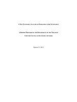
line (SDA) must remain stable whenever the clock line
(SCL) is high. Changes in the data line while the clock
line is high are interpreted as a START or STOP condition. A typical transfer format is shown in Figure 1.
INTRODUCTION
The Microchip Technology Inc.’s 24CXX and 85CXX
Serial EEPROMs feature a two wire serial interface bus.
The bus protocol is I2C compatible. Interface to a serial
port with I2C bus protocol in a microcontroller is trivial.
This application note is intended for design engineers
who want to develop their software programs to communicate a microcontroller with a 2-wire bus Serial EEPROM
through a general purpose I/O port.
After the START condition, a slave address is sent. This
address is 7-bits long, the eighth bit is a data direction bit.
(R/W - a logical ‘0’ indicates a transmission WRITE, a
logical ‘1’ represents a request for data READ. A data
transfer is always terminated by a STOP condition
generated by the master controller. However, if a master
still wishes to communicate on the bus, it can generate
another START condition and address another slave
without first generating a STOP condition. Various combinations of read/write formats are then possible within
such transfer.
Unlike the 3-wire bus Serial EEPROMs, the 24CXX/
85CXX communicate with any microcontroller only by a
serial data I/O line (SDA) and a serial clock (SCL). Chip
select is not required. Data transfer may be initiated only
when the bus is not busy. During such transfer, the data
FIGURE 1 - TRANSFER FORMAT
ACK SIGNAL
FROM RECEIVER
MSB - LSB
MSB - LSB
MSB - LSB
SDA
SCL
7
S
1-7
START
CONDITION
8
ADDRESS R/W
9
1-7
ACK
8
DATA
9
1-7
ACK
8
DATA
P
9
ACK
STOP
CONDITION
FIGURE 2 - A SIMPLE HARDWARE CONNECTION
+5V
1
NOTE 2
2
3
4
NOTE 1:
NOTE 2:
A0
Vcc
8
7
A1
A2
SCL
Vss
SDA
+5V
+5V
14
22K
x2
Vdd
OSC1
NOTE 1
6
5
12
•
•
NC PIN FOR 85Cxx,
NF PIN FOR 24C01A AND
WP PIN FOR 24C02A/24C04A
CHIP ADDRESS INPUTS, MUST BE
TIED TO Vcc OR Vss.
13
16
XTAL
RB6
OSC2
RB7
15
PIC 16C54 - XT
Vss
5
DS00515D-page 1
© 1993 Microchip Technology Inc.
7-1
Communicating with the I2C™ Bus Using the PIC16C5X
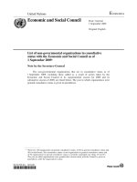
An example program has been provided in Appendix A
containing all PIC16C54 routines needed to exercise a
24CXX or 85CXX device. A simple hardware connection
is illustrated in Figure 2. A maximum of eight 24C01A/
24C02A/85C72/85C82's, or four 24C04A/85C92's can
be addressed by a microcontroller on the same two wire
bus without additional interfaces. Each device is identified by its Chip Address and will only respond to the
correct slave address. A detailed bus flow is shown in
Figure 3.
Figure 3 as shown below describes how the bit stream
is set up for READ and WRITE mode in the microcomputer programming software prior to sending it on the
two wire serial bus.
The stop condition, after the write sequence, starts the
internal self-timed write cycle which may last up to 6
milliseconds (.7 ms per byte). Acknowledge signal
should be monitored during this period.
Author:
Bruce Negley
Memory Products Division
FIGURE 3A - SETTING THE INTERNAL WORD ADDRESS OF THE 24CXX/85CXX
SCL
SDA
1
0
1
0
A2
A1
A0
W
Ack
4
5
A7
A6
A5
A4
A3
A2
A1
A0
Ack
SD
1
3
2
6
1. START CONDITION
2. 4 BIT DEVICE CODE 1010 FOR 24CXX/85CXX
3. DEVICE ADDRESS A0=PA, HIGH ORDER ADDRESS
BIT A8 FOR 24C04A/85C92
4. 0=WRITE TO ADDRESS REGISTER
7
5. EEPROM DRIVES BUS LOW WITH ACKNOWLEDGEMENT
(TIMEOUT IF NO RESPONSE)
6. ADDRESS FOR DATA, A7-A0 (MSB-LSB)
7. BUS LOW FOR ACKNOWLEDGEMENT
FIGURE 3B - BYTE WRITE SEQUENCE
SCL
SDA
d7
d6
d5
d4
d3
d2
d1
d0
Ack
d7
d6
d5
d4
d3
d2
d1
d0
Ack
d7
SD
FIRST DATA BYTE
SECOND DATA BYTE
THIRD DATA
BYTE, ETC.
STOP
CONDITION
FIGURE 3C - READ MODE SEQUENCE
SCL
SDA
1
0
1
0
A2
A1
A0
R
Ack
4
5
d7
d6
d5
d4
d3
d2
d1
d0
Ack
d7
SD
1
2
3
1. START CONDITION
2. 4 BIT DEVICE CODE 1010 FOR 24CXX/85CXX
3. DEVICE ADDRESS A2, A1, A0. A0 = PA, HIGH ORDER
ADDRESS BIT A8 FOR 24C04A/85C92
4. 1 = READ MODE
6
7
8
5. ACKNOWLEDGE FROM EEPROM
6. FIRST DATA BYTE
7. SECOND DATA BYTE, ETC.
8. STOP CONDITION
READ UP TO 128 BYTES (24C01A, 85C72)
READ UP TO 256 BYTES (24C02A/04A, 85C82/92)
DS00515D-page 2
© 1993 Microchip Technology Inc.
7-2
Communicating with the I2C™ Bus Using the PIC16C5X
Appendix A:
MPALC CROSS ASSEMBLER
15:36:02 1990 PAGE 1
2.00
d:\seeprom\appnotes\i2cbus.asm
Apr 11
TWO WIRE/I2C BUS INTERFACE WITH PIC16C5x
0001
0002
0003
0004
0005
TITLE “TWO WIRE/I2C BUS INTERFACE WITH PIC16C5x”
;
LIST
P=16C54
;
;******************************************************
0006
;**
;
Two wire/I2C Bus READ/WRITE Sample Routines
of Microchip’s 24CXX/85CXX serial CMOS
0007
0008
;**
;**
EEPROM interfacing to a PIC16C54 8-bit CMOS
single chip microcomputer
0009
;**
0010
;**
Part use = PIC16C54-XT/JW
0011
;**
;
;
Note: 1) All timings are based on a
reference crystal frequency of 2 MHz which
is equivalent to an instruction cycle
0012
0013
;**
;**
;
time of 2 usec.
2) Address and literal values are read
in octal unless otherwise specified.
;
;
;
;
;
;
;
;
3) The following sample program is
intended to interface a two wire/I2C
serial EEPROM with a PIC16C54 on a
stand-alone application only.
In the case where the two wire bus is
multiplexing with other circuitry, it is
recommended to check the 24CXX/85CXX in
standby mode to avoid bus contention.
0014
;**
0015
0016
;*******************************************************
;
0017
0018
;-----------------------------------------------------;
Files Assignment
0019
;------------------------------------------------------
0020
;
0021
0002
PC
EQU
2
; Program counter
0022
0004
FSR
EQU
4
; File Select Register
0023
0005
RA
EQU
5
; Port A use to select
; device address
0024
0006
RB
EQU
6
; RB7 = SDA, RB6 = SCL
0025
;
0026
0010
STATUS
EQU
10
; Status register
0027
0011
FLAG
EQU
11
; Common flag bits
; register
0028
0012
EEPROM
EQU
12
; Bit buffer
0029
0013
ERCODE
EQU
13
; Error code (to indicate
; bus status)
0030
0020
ADDR
EQU
20
; Address register
0031
0021
DATAI
EQU
21
; Stored data input
; register
DS00515D-page 3
© 1993 Microchip Technology Inc.
7-3
7
Communicating with the I2C™ Bus Using the PIC16C5X
0032
0022
DATAO
EQU
22
; Stored data output
; register
0033
0023
SLAVE
EQU
23
; Device address
; (1010xxx0)
0034
0024
TXBUF
EQU
24
; TX buffer
0035
0025
RXBUF
EQU
25
; RX buffer
0036
0026
COUNT
EQU
26
; Bit counter
0037
;
0038
0030
TIMER0
EQU
30
; Delay timer0
0039
0031
TIMER1
EQU
31
; Delay timer1
0040
;
0041
;
0042
;------------------------------------------------------
0043
;
0044
;------------------------------------------------------
Bit Assignments
0045
;
0046
;
0047
;
0048
0000
0049
;
0050
;
0051
;
0052
0007
DI
0053
0006
DO
0054
;
0055
;
0056
;
0057
0007
0058
0006
0059
;
0060
;
0061
;
FLAG Bits
ERROR
EQU
0
; Error flag
EQU
7
; EEPROM input
EQU
6
; EEPROM output
SDA
EQU
7
; RB7, data in/out
SCL
EQU
6
; RB6, serial clock
EEPROM Bits
I2C Device Bits
END FILES/BITS EQUATE
0062
;
0063
;------------------------------------------------------
0064
;
;
0065
;------------------------------------------------------
0066
;
input
0067
;
output :
0068
;
0069
;
0070
;
0071
;
0072
;
1
:
SCL locked low by device (bus is still
busy)
0073
;
2
:
SDA locked low by device (bus is still
busy)
0074
;
3
:
No acknowledge from device (no
handshake)
0075
;
4
:
SDA bus not released for master to
generate STOP bit
Two wire/I2C - CPU communication error status table
and subroutine
:
W-reg
= error code
ERCODE = error code
FLAG(ERROR)
code
= 1
error status mode
-------- -----------------------------------
DS00515D-page 4
© 1993 Microchip Technology Inc.
7-4
Communicating with the I2C™ Bus Using the PIC16C5X
0076
;------------------------------------------------------
0077
;
0078
;
;
Subroutine to identify the status of the serial clock
(SCL) and serial data
0079
;
;
(SDA) condition according to the error status table. 0080
Codes generated are useful for bus/device diagnosis.
0081
;
0082
ERR
0083
0000
3411
BTFSS
FLAG,ERROR
; Remain as first error
; encountered
0084
0001
0053
MOVWF
ERCODE
; Save error code
0085
0002
2411
BSF
FLAG,ERROR
; Set error flag
0086
0003
4000
RETLW
0
0087
;
0088
;------------------------------------------------------
0089
;
0090
;------------------------------------------------------
0091
;
input
: none
0092
;
output
: initialize bus communication
0093
;------------------------------------------------------
0094
;
0095
;
;
Generate START bit (SCL is high while SDA goes from
high to low transition) and check status of the
0096
;
serial clock.
0097
BSTART
START bus communication routine
0098
0004
6077
MOVLW
B’00111111' ; Put SCL, SDA line in
; output state
0099
0005
0006
TRIS
RB
0100
0006
2706
BSF
RB,SCL
; Set clock high
0101
0007
6001
MOVLW
1
; Ready error status
; code 1
0102
0010
3706
BTFSS
RB,SCL
; Locked?
0103
0011
4400
CALL
ERR
; SCL locked low by device
0104
0012
2346
BCF
RB,SDA
; high
; SDA goes low during SCL
0105
0013
0000
NOP
0106
0014
0000
NOP
0107
0015
0000
NOP
0108
0016
2306
BCF
RB,SCL
0109
0017
4000
RETLW
0
; Timing adjustment
; Start clock train
0110
;
0111
;END SUB
0113
;
0114
;------------------------------------------------------
0115
;
0116
;------------------------------------------------------
0117
;
Input :
0118
;
Output
0119
;------------------------------------------------------
0120
;
0121
; Generate STOP bit (SDA goes from low to high during
; SCL high state)
STOP bus communication routine
None
:
Bus communication, STOP condition
DS00515D-page 5
© 1993 Microchip Technology Inc.
7-5
7
Communicating with the I2C™ Bus Using the PIC16C5X
0122
; and check bus conditions.
0123
;
0124
BSTOP
0125
0020
2346
BCF
0126
0021
0000
NOP
RB,SDA
; Return SDA to low
0127
0022
0000
NOP
0128
0023
2706
0129
0024
6001
BSF
RB,SCL
; Set SCL high
MOVLW
1
0130
0025
; Ready error code 1
3706
BTFSS
RB,SCL
; High?
0131
0026
4400
CALL
ERR
; No, SCL locked low by
; device
0132
0027
2746
BSF
RB,SDA
; SDA goes from low to
; high during SCL high
0133
0030
6004
MOVLW
4
; Ready error code 4
0134
0031
3746
BTFSS
RB,SDA
; High?
0135
0032
4400
CALL
ERR
; for STOP
; No, SDA bus not release
0136
0033
4000
RETLW
0
0137
;
0138
;END SUB
0139
;
0040
;------------------------------------------------------
0141
;
;
0142
;------------------------------------------------------
0143
;
Input :
0144
;
Output
00145
;------------------------------------------------------
0146
;
0147
Serial data send from PIC16CXX to serial EEPROM,
bit-by-bit subroutine
None
:
To (DI) of serial EEPROM device
BITIN
0148
0034
6277
MOVLW
B’10111111' ; Force SDA line as input
0149
0035
0006
TRIS
RB
0150
0036
2746
BSF
RB,SDA
0151
0037
2352
BCF
EEPROM,DI
0152
0040
2706
BSF
RB,SCL
0153
0041
6001
MOVLW
1
0154
0042
3306
BTFSC
RB,SCL
0155
0043
5047
GOTO
BIT1
0156
0044
3411
BTFSS
FLAG,ERROR
0157
0045
0053
MOVWF
ERCODE
; Save error code
0158
0046
2411
BSF
FLAG,ERROR
; Set error flag
0160
0047
3346
BTFSC
RB,SDA
; Read SDA pin
0161
0050
2752
BSF
EEPROM,DI
; DI = 1
0162
0051
0000
NOP
0163
0052
2306
BCF
RB,SCL
; Return SCL to low
0164
0053
4000
RETLW
0
0159
; Set SDA for input
; Clock high
; Skip if SCL
is high
; Remain as first error
; encountered
BIT1
0165
;
0166
;END SUB
0168
;
; Delay
DS00515D-page 6
© 1993 Microchip Technology Inc.
7-6
Communicating with the I2C™ Bus Using the PIC16C5X
0169
;------------------------------------------------------
0170
;
;
0171
;------------------------------------------------------
0172
;
Input :
0173
;
Output
Serial data receive from serial EEPROM to PIC16CXX,
bit-by-bit subroutine
EEPROM file
;
:
to PIC
From (DO) of serial EEPROM device
0174
;------------------------------------------------------
0175
;
0176
BITOUT
0177
0054
6077
MOVLW
0178
0055
0006
TRIS
RB
0179
0056
3712
BTFSS
EEPROM,DO
0180
0057
5070
GOTO
BIT0
0181
0060
2746
BSF
RB,SDA
0182
0061
6002
MOVLW
2
0183
0062
3346
BTFSC
RB,SDA
0184
0063
5074
GOTO
CLK1
0185
0064
3411
BTFSS
FLAG,ERROR
0186
0065
0053
MOVWF
ERCODE
; Save error code
0187
0066
2411
BSF
FLAG,ERROR
; Set error flag
0188
0067
5074
GOTO
CLK1
; SDA locked low by device
RB,SDA
; Output bit 0
0189
B’00111111' ; Set SDA, SCL as outputs
; Output bit 0
; Check for error code 2
; Remain as first error
; encountered
;
0190
BIT0
0191
0070
2346
BCF
0192
0071
0000
NOP
0193
0072
0000
NOP
0194
0073
0000
0195
; Delay
NOP
CLK1
0196
0074
2706
BSF
RB,SCL
0197
0075
6001
MOVLW
1
; Error code 1
0198
0076
3306
BTFSC
RB,SCL
; SCL locked low?
0199
0077
5103
GOTO
BIT2
; No.
0200
0100
3411
BTFSS
FLAG,ERROR
; Yes.
0201
0101
0053
MOVWF
ERCODE
; Save error code
0202
0102
2411
BSF
FLAG,ERROR
; Set error flag
0204
0103
0000
NOP
0205
0104
0000
NOP
0206
0105
2306
BCF
RB,SCL
; Return SCL to low
0207
0106
4000
RETLW
0
0203
7
BIT2
0208
;
0209
;END SUB
0211
;
0212
;
0213
;------------------------------------------------------
0214
;
0215
;------------------------------------------------------
0216
;
RECEIVE DATA subroutine
Input
:
None
DS00515D-page 7
© 1993 Microchip Technology Inc.
7-7
Communicating with the I2C™ Bus Using the PIC16C5X
0217
;
0218
;------------------------------------------------------
0219
;
0220
Output
:
RXBUF = Receive 8-bit data
RX
0221
0107
6010
MOVLW
.8
0222
0110
0066
MOVWF
COUNT
0223
0111
0165
CLRF
RXBUF
RLF
RXBUF
0224
; 8 bits of data
;
0225
RXLP
0226
0112
1565
0227
0113
SKPC
0228
0113
3403
0228
0114
2025
0229
0115
0230
0115
3003
BTFSC
3,0
0230
0116
2425
BSF
RXBUF,0
0231
0117
4434
CALL
BITIN
0232
0120
3352
BTFSC
EEPROM,DI
0233
0121
2425
BSF
RXBUF,0
; Input bit =1
0234
0122
1366
DECFSZ
COUNT
; 8 bits?
0235
0123
5112
GOTO
RXLP
0236
0124
2712
BSF
EEPROM,DO
; Set acknowledge bit = 1
0237
0125
4454
CALL
BITOUT
; to STOP further input
0238
0126
4000
RETLW
0
+
BTFSS
3,0
BCF
RXBUF,0
; Shift data to buffer
; carry —> f(0)
SKPNC
+
0239
;
0240
;END SUB
0241
;
0242
;----------------------------------------------------
0243
;
0244
;----------------------------------------------------
0245
;
Input
:
TXBUF
0246
;
Output
:
Data X’mitted to EEPROM device
0247
;----------------------------------------------------
0248
;
0249
TRANSMIT DATA subroutine
TX
0250
0127
6010
MOVLW
.8
0251
0130
0066
MOVWF
COUNT
0252
;
0253
TXLP
0254
0131
2312
BCF
EEPROM,DO
; Shift data bit out.
0255
0132
3364
BTFSC
TXBUF,7
; bit = 0
; If shifted bit=0, data
0256
0133
2712
BSF
EEPROM,DO
; Otherwise data bit = 1
0257
0134
4454
CALL
BITOUT
; Serial data out
0258
0135
1564
RLF
TXBUF
; Rotate TXBUF left
0259
0136
0260
0136
3403
0260
0137
2024
0261
0140
0262
0140
SKPC
+
; f(6) —> f(7)
BTFSS
3,0
BCF
TXBUF,0
SKPNC
3003
+
; f(7) —> carry
; carry —> f(0)
BTFSC
3,0
DS00515D-page 8
© 1993 Microchip Technology Inc.
7-8
Communicating with the I2C™ Bus Using the PIC16C5X
0262
0141
2424
BSF
TXBUF,0
0263
0142
1366
DECFSZ
COUNT
0264
0143
5131
GOTO
TXLP
; No.
0265
0144
4434
CALL
BITIN
; Read acknowledge bit
0266
0145
6003
MOVLW
3
0267
0146
3352
BTFSC
EEPROM,DI
; Check for
; acknowledgement
0268
0147
4400
CALL
ERR
; No acknowledge from
; device
0269
0150
4000
RETLW
0
; 8 bits done?
0270
;
0271
;END SUB
0273
;
0274
;----------------------------------------------------
0275
;
0276
;----------------------------------------------------
0277
;
0278
;
0279
;
0280
;
0281
;----------------------------------------------------
0282
0283
BYTE-WRITE, write one byte to EEPROM device
Input
:
DATAO = data to be written
ADDR = destination address
SLAVE = device address (1010xxx0)
Output
:
Data written to EEPROM device
;
0200
0284
ORG
200
; The location for BYTE; WRITE routine can be
;
0285
; assigned anywhere
; between (377- 777)
; octal.
WRBYTE
0286
0200
1023
MOVF
SLAVE,W
; Get SLAVE address
0287
0201
0064
MOVWF
TXBUF
; to TX buffer
0288
0202
4404
CALL
BSTART
; Generate START bit
0289
0203
4527
CALL
TX
; Output SLAVE address
0290
0204
1020
MOVF
ADDR,W
; Get WORD address
0291
0205
0064
MOVWF
TXBUF
; into buffer
0292
0206
4527
CALL
TX
; Output WORD address
0293
0207
1022
MOVF
DATAO,W
; Move DATA
0294
0210
0064
MOVWF
TXBUF
; into buffer
0295
0211
4527
CALL
TX
; Output DATA and detect
; acknowledgement
0296
0212
4420
CALL
BSTOP
; Generate STOP bit
0297
;
0298
;
0299
;
0300
;----------------------------------------------------
0301
;
;
0302
;----------------------------------------------------
0303
;
0304
;
0305
;
BYTE-READ, read one byte from serial EEPROM
device
Input
:
ADDR
= source address
SLAVE = device address (1010xxx0)
Output
:
DATAI = data read from serial
EEPROM
DS00515D-page 9
© 1993 Microchip Technology Inc.
7-9
7
Communicating with the I2C™ Bus Using the PIC16C5X
0306
;----------------------------------------------------
0307
0308
;
0300
ORG
0309
;
0310
RDBYTE
300
; The location for BYTE; READ routine can be
; assigned anywhere
; between (377-777) octal.
0311
0300
1023
MOVF
SLAVE,W
; Move SLAVE address
0312
0301
0064
MOVWF
TXBUF
; into buffer (R/W = 0)
0313
0302
4404
CALL
BSTART
; Generate START bit
0314
0303
4527
CALL
TX
; Output SLAVE address.
; Check ACK.
0315
0304
1020
MOVF
ADDR,W
; Get WORD address
0316
0305
0064
MOVWF
TXBUF
0317
0306
4527
CALL
TX
; Output WORD address.
; Check ACK.
0318
0307
4404
CALL
BSTART
; START READ (if only one
; device
0319
0310
1023
MOVF
SLAVE,W
; is connected to the I2C
; bus)
0320
0311
0064
MOVWF
TXBUF
0321
0312
2424
BSF
TXBUF,0
; Specify READ mode
; (R/W = 1)
0322
0313
4527
CALL
TX
; Output SLAVE address
0323
0314
4507
CALL
RX
; READ in data and
; acknowledge
0324
0315
4420
CALL
BSTOP
; Generate STOP bit
0325
0316
1065
MOVF
RXBUF
; Save data from buffer
0326
0317
0061
MOVWF
DATAI
; to DATAI file.
0327
;
0328
;
0329
;
0330
END
%ASM-I, No Errors, No Warnings
DS00515D-page 10
© 1993 Microchip Technology Inc.
7-10
Note the following details of the code protection feature on PICmicro® MCUs.
•
•
•
•
•
•
The PICmicro family meets the specifications contained in the Microchip Data Sheet.
Microchip believes that its family of PICmicro microcontrollers is one of the most secure products of its kind on the market today,
when used in the intended manner and under normal conditions.
There are dishonest and possibly illegal methods used to breach the code protection feature. All of these methods, to our knowledge, require using the PICmicro microcontroller in a manner outside the operating specifications contained in the data sheet.
The person doing so may be engaged in theft of intellectual property.
Microchip is willing to work with the customer who is concerned about the integrity of their code.
Neither Microchip nor any other semiconductor manufacturer can guarantee the security of their code. Code protection does not
mean that we are guaranteeing the product as “unbreakable”.
Code protection is constantly evolving. We at Microchip are committed to continuously improving the code protection features of
our product.
If you have any further questions about this matter, please contact the local sales office nearest to you.
Information contained in this publication regarding device
applications and the like is intended through suggestion only
and may be superseded by updates. It is your responsibility to
ensure that your application meets with your specifications.
No representation or warranty is given and no liability is
assumed by Microchip Technology Incorporated with respect
to the accuracy or use of such information, or infringement of
patents or other intellectual property rights arising from such
use or otherwise. Use of Microchip’s products as critical components in life support systems is not authorized except with
express written approval by Microchip. No licenses are conveyed, implicitly or otherwise, under any intellectual property
rights.
Trademarks
The Microchip name and logo, the Microchip logo, FilterLab,
KEELOQ, microID, MPLAB, PIC, PICmicro, PICMASTER,
PICSTART, PRO MATE, SEEVAL and The Embedded Control
Solutions Company are registered trademarks of Microchip Technology Incorporated in the U.S.A. and other countries.
dsPIC, ECONOMONITOR, FanSense, FlexROM, fuzzyLAB,
In-Circuit Serial Programming, ICSP, ICEPIC, microPort,
Migratable Memory, MPASM, MPLIB, MPLINK, MPSIM,
MXDEV, PICC, PICDEM, PICDEM.net, rfPIC, Select Mode
and Total Endurance are trademarks of Microchip Technology
Incorporated in the U.S.A.
Serialized Quick Turn Programming (SQTP) is a service mark
of Microchip Technology Incorporated in the U.S.A.
All other trademarks mentioned herein are property of their
respective companies.
© 2002, Microchip Technology Incorporated, Printed in the
U.S.A., All Rights Reserved.
Printed on recycled paper.
Microchip received QS-9000 quality system
certification for its worldwide headquarters,
design and wafer fabrication facilities in
Chandler and Tempe, Arizona in July 1999. The
Company’s quality system processes and
procedures are QS-9000 compliant for its
PICmicro® 8-bit MCUs, KEELOQ® code hopping
devices, Serial EEPROMs and microperipheral
products. In addition, Microchip’s quality
system for the design and manufacture of
development systems is ISO 9001 certified.
2002 Microchip Technology Inc.
M
WORLDWIDE SALES AND SERVICE
AMERICAS
ASIA/PACIFIC
Japan
Corporate Office
Australia
2355 West Chandler Blvd.
Chandler, AZ 85224-6199
Tel: 480-792-7200 Fax: 480-792-7277
Technical Support: 480-792-7627
Web Address:
Microchip Technology Australia Pty Ltd
Suite 22, 41 Rawson Street
Epping 2121, NSW
Australia
Tel: 61-2-9868-6733 Fax: 61-2-9868-6755
Microchip Technology Japan K.K.
Benex S-1 6F
3-18-20, Shinyokohama
Kohoku-Ku, Yokohama-shi
Kanagawa, 222-0033, Japan
Tel: 81-45-471- 6166 Fax: 81-45-471-6122
Rocky Mountain
China - Beijing
2355 West Chandler Blvd.
Chandler, AZ 85224-6199
Tel: 480-792-7966 Fax: 480-792-7456
Microchip Technology Consulting (Shanghai)
Co., Ltd., Beijing Liaison Office
Unit 915
Bei Hai Wan Tai Bldg.
No. 6 Chaoyangmen Beidajie
Beijing, 100027, No. China
Tel: 86-10-85282100 Fax: 86-10-85282104
Atlanta
500 Sugar Mill Road, Suite 200B
Atlanta, GA 30350
Tel: 770-640-0034 Fax: 770-640-0307
Boston
2 Lan Drive, Suite 120
Westford, MA 01886
Tel: 978-692-3848 Fax: 978-692-3821
Chicago
333 Pierce Road, Suite 180
Itasca, IL 60143
Tel: 630-285-0071 Fax: 630-285-0075
Dallas
4570 Westgrove Drive, Suite 160
Addison, TX 75001
Tel: 972-818-7423 Fax: 972-818-2924
Detroit
Tri-Atria Office Building
32255 Northwestern Highway, Suite 190
Farmington Hills, MI 48334
Tel: 248-538-2250 Fax: 248-538-2260
Kokomo
2767 S. Albright Road
Kokomo, Indiana 46902
Tel: 765-864-8360 Fax: 765-864-8387
Los Angeles
18201 Von Karman, Suite 1090
Irvine, CA 92612
Tel: 949-263-1888 Fax: 949-263-1338
China - Chengdu
Microchip Technology Consulting (Shanghai)
Co., Ltd., Chengdu Liaison Office
Rm. 2401, 24th Floor,
Ming Xing Financial Tower
No. 88 TIDU Street
Chengdu 610016, China
Tel: 86-28-6766200 Fax: 86-28-6766599
China - Fuzhou
Microchip Technology Consulting (Shanghai)
Co., Ltd., Fuzhou Liaison Office
Unit 28F, World Trade Plaza
No. 71 Wusi Road
Fuzhou 350001, China
Tel: 86-591-7503506 Fax: 86-591-7503521
China - Shanghai
Microchip Technology Consulting (Shanghai)
Co., Ltd.
Room 701, Bldg. B
Far East International Plaza
No. 317 Xian Xia Road
Shanghai, 200051
Tel: 86-21-6275-5700 Fax: 86-21-6275-5060
China - Shenzhen
150 Motor Parkway, Suite 202
Hauppauge, NY 11788
Tel: 631-273-5305 Fax: 631-273-5335
Microchip Technology Consulting (Shanghai)
Co., Ltd., Shenzhen Liaison Office
Rm. 1315, 13/F, Shenzhen Kerry Centre,
Renminnan Lu
Shenzhen 518001, China
Tel: 86-755-2350361 Fax: 86-755-2366086
San Jose
Hong Kong
Microchip Technology Inc.
2107 North First Street, Suite 590
San Jose, CA 95131
Tel: 408-436-7950 Fax: 408-436-7955
Microchip Technology Hongkong Ltd.
Unit 901-6, Tower 2, Metroplaza
223 Hing Fong Road
Kwai Fong, N.T., Hong Kong
Tel: 852-2401-1200 Fax: 852-2401-3431
New York
Toronto
6285 Northam Drive, Suite 108
Mississauga, Ontario L4V 1X5, Canada
Tel: 905-673-0699 Fax: 905-673-6509
India
Microchip Technology Inc.
India Liaison Office
Divyasree Chambers
1 Floor, Wing A (A3/A4)
No. 11, O’Shaugnessey Road
Bangalore, 560 025, India
Tel: 91-80-2290061 Fax: 91-80-2290062
Korea
Microchip Technology Korea
168-1, Youngbo Bldg. 3 Floor
Samsung-Dong, Kangnam-Ku
Seoul, Korea 135-882
Tel: 82-2-554-7200 Fax: 82-2-558-5934
Singapore
Microchip Technology Singapore Pte Ltd.
200 Middle Road
#07-02 Prime Centre
Singapore, 188980
Tel: 65-6334-8870 Fax: 65-6334-8850
Taiwan
Microchip Technology Taiwan
11F-3, No. 207
Tung Hua North Road
Taipei, 105, Taiwan
Tel: 886-2-2717-7175 Fax: 886-2-2545-0139
EUROPE
Denmark
Microchip Technology Nordic ApS
Regus Business Centre
Lautrup hoj 1-3
Ballerup DK-2750 Denmark
Tel: 45 4420 9895 Fax: 45 4420 9910
France
Microchip Technology SARL
Parc d’Activite du Moulin de Massy
43 Rue du Saule Trapu
Batiment A - ler Etage
91300 Massy, France
Tel: 33-1-69-53-63-20 Fax: 33-1-69-30-90-79
Germany
Microchip Technology GmbH
Gustav-Heinemann Ring 125
D-81739 Munich, Germany
Tel: 49-89-627-144 0 Fax: 49-89-627-144-44
Italy
Microchip Technology SRL
Centro Direzionale Colleoni
Palazzo Taurus 1 V. Le Colleoni 1
20041 Agrate Brianza
Milan, Italy
Tel: 39-039-65791-1 Fax: 39-039-6899883
United Kingdom
Arizona Microchip Technology Ltd.
505 Eskdale Road
Winnersh Triangle
Wokingham
Berkshire, England RG41 5TU
Tel: 44 118 921 5869 Fax: 44-118 921-5820
03/01/02
2002 Microchip Technology Inc.