AN0571 communicating with EEPROM in MTA85XXX
Bạn đang xem bản rút gọn của tài liệu. Xem và tải ngay bản đầy đủ của tài liệu tại đây (145.13 KB, 13 trang )
Communicating With EEPROM In MTA85XXX
AN571
Communicating With EEPROM In MTA85XXX
The frequency of operation is assumed to be 4MHz and
the code has been verified over the entire operating
voltage range of the MTA85XXX. This code was tested
with the fuse settings:
1.0 INTRODUCTION
The Microchip MTA85XXX family of microcontrollers are
multichip modules which contain a PIC16C54A or
PIC16C58A microcontroller and a Microchip Technology
24LC01B or 24LC02B EEPROM. This application note
is intended to provide users with the most efficient code
for I2C™-like communication between the EEPROM and
the microcontroller in a PICSEE™ configuration, which
will leave the user a maximum amount of code space
and data RAM for the core application. The code
contained in this application note will allow the
PIC16C5XA microcontroller to act as the I2C master.
The 24LC0XB EEPROM devices have I2C slave protocol implemented on-chip. Please refer to the Microchip
Databook for further details on the 24LC0XB EEPROM.
Note that this application note is optimized for use in
either the PICSEE, or PIC16C5X plus EEPROM from
Microchip. If a discrete PIC16C5X and generic serial
EEPROM are to be used, refer to application note
AN554 which details a complete I2C implementation.
OSC = XT, WDT = ON, CP = OFF, CKSUM = 6715
2.0 OPERATION
2.1 General Operation
This application note will function with both bonding
options of the MTA85XXX. Please refer to the
MTA85XXX datasheet for further details. This application note will light LEDs on port B to indicate that the data
is being written to the EEPROM or to output data read
from the EEPROM.
The SDA and SCL bits of the EEPROM must be initialized to ‘1’s before calling any of the EEPROM subroutines. This is done in the beginning of the MAIN routine.
The start bit will not be initiated properly if these bits are
not initialized prior to calling the EEPROM routines.
The files which compose this application note (and their
encapsulated post script print files) can be found on the
Microchip BBS. The EEPROM communication code
contained within this application note can be easily
inserted into the users application code.
The registers EEADD and EEDATA are used to communicate EEPROM address and data information to and
from the EEPROM, as described below.
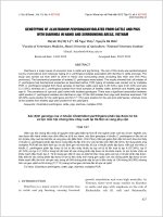
FIGURE 2-1 SCHEMATIC
VCC
5K
MTA85XXX
1
J1
1
J2
20pf
4MHz
VCC
2
2
3
3
20pf
10K
10K
VCC
NOTE:J11-2Read
= EEPROM
=
2-3Write EEPROM
1 SDA
VDD 20
2 SCL
SVDD/ RB7 19
OR RB7
3 OSC2
RB6 18
4 OSC1
RB5 17
5 RA0
RB4 16
6 RA1
RB3 15
7 RA2
RB2 14
8 RA3
RB1 13
9 RTCC
RB0 12
10 NMCLR
VSS 11
VCC
.1uf
1K
10K
J21-21K EEPROM
= (MTA85XX1)
2-32K EEPROM=(MTA85XX2)
© 1994 Microchip Technology Inc.
DS00571A-page 1
6-21
6
Communicating With EEPROM In MTA85XXX
address is incremented by 1 and the data decremented
by 1 after each byte is written, until the EE array is full.
An AAH is output to port B after the write has completed
(actually as the last byte is writing).
2.2 Hardware Configuration
The schematic for this application note is located in
figure 2-1. For the user’s application, the pins used for
SDA and SCL can be easily redefined and the switches
will not be necessary. This application example shows
the MTA85XXX driving an array of LEDs to indicate
writing to the EEPROM is in progress.
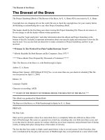
2.6 Read_Current and Read_Random
Operation
A read operation will attempt to read the data at the
supplied or current address until an acknowledge is
received. If an acknowledge is not received, the part will
time out after a WDT period. If a Read_Random is being
performed, the address is supplied in EEADD. If a
Read_Current is being performed, the current address
pointer inside the EEPROM is used. In both
Read_Random and Read_Current the data is read into
the EEDATA register.
2.3 Switches for array size and to determine
read/write
Bits RA0 and RA1 are used to determine if the user
would like to read or write the array and to select the
array size (1K or 2K). Bits RA2 and RA3 are used for
SCL and SDA.
RA0 = ‘0’ for 1K EEPROM
In this application note, the port B LEDs are used to
display the array content during a read operation. A 1second timer is called between each byte so the data
can be read on the LEDs. Note that with the MTA85X1X
version (RB7 = SEEVDD), RB7 must always = ‘1’ when
the EEPROM is being accessed. The EEPROM address pointer (used for a read current address) will be
reset to the last EEPROM address if RB7 is set to a ‘0’
at any time. Due to this, the RB7 pin is always set to a
‘1’ during a Read_Current operation (even if the data
read is a ‘0’ in the high order bit, a one will be output on
RB7 to keep from resetting the EEPROM’s internal
address). MTA85X0X users may want to comment out
the line which sets the RB7 to a ‘1’ during a Read_Current
operation, so that they will receive the data read from the
EEPROM on the LEDs without the data appearing on
RB7 altered.
RA1 = ‘0’ for read EEPROM
RA0 = ‘1’ for 2K EEPROM
RA1 = ‘1’ for write EEPROM
2.4 EEPROM Subroutines
The code in this application note is capable of performing byte writes, current address reads, and random
address reads. The names of the subroutines are:
Write_Byte
Write data supplied in register EEDATA
at address supplied in register EEADD
Read_Random Read data into register EEDATA from
address supplied in register EEADD
Read_Current Read data into register EEDATA from
current address in EEPROM memory.
Note that the EEPROMs used in the MTA85XXX devices are also capable of page writes, however, page
writes are not detailed by this application note. Refer to
AN567 for details on page write.
2.7 Code Size
The total amount of program memory space required is
148 bytes. The major sections are as follows:
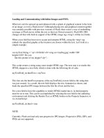
2.5 Write_Byte Operation
EEPROM Subroutines
71 bytes
During a Write_Byte operation the master will set address and data information into the EEADD and EEDATA
registers. After receiving the acknowledge from the
EEPROM that the current EEADD and EEDATA have
been received, new values will be loaded into the EEADD
and EEDATA registers. The EEPROM initiates a self
timed write after the acknowledge, during which time it
will not accept or acknowledge other input. The master
falls into a loop trying to input the new address and data
into the EEPROM. This loop will continue until the
EEPROM finishes the self timed write and acknowledges receipt of the new address and data information.
EEPROM Initialization
4 bytes
initialize SDA and SCL
Read/Write Setup
13 bytes
Read Array
27 bytes
Write Array
15 bytes
1 second timer
14 bytes
End of program loop
4 bytes
This application note uses the 8-bit port B to provide an
LED display. During a write, the LEDs should initialize
to all ‘1’ and then set to ‘0’, 1 bit at a time, with each bit
indicating that another 1/8th of the EEPROM array has
been written. The entire operation takes less than 1
second after applying power or resetting the part. The
data is initialized to FFH and the address to 00H. The
DS00571A-page 2
© 1994 Microchip Technology Inc.
6-22
Communicating With EEPROM In MTA85XXX
3.0 TIMINGS (ASSUME 4MHZ)
4.0 I2C COMPATIBILITY
Detailed timing diagrams are given in Section 8.
NOTE: Code is not strictly I2C compatible on all timing
parameters, but is designed to work with a Microchip
24LC01B or 24LC02B EEPROM from 3 to 6.25 volts.
Commented NOPs have been included which can be
put in place to gain I2C timing compatibility. Also note
that ‘1’s are driven onto the bus (not floated) by the
master in most write circumstances, except where bus
contention from the EEPROM slave could result.
Write operation will take approximately 350µs + standard write time (Figure 8-1).
Read random address operation will take approximately
350µs (Figure 8-2).
Read current address will take approximately 250µs
(Figure 8-3).
5.0 ASSEMBLY CODE LISTING
TITLE “APP-NOTE PER I2C-BUS”
LIST P=16C54 , C=132
;LIST
P=PIC16C58 C=132
; PIC16C5X to 24LC01B or 24LC02B EEPROM communication code.
; Based on Franco code.
; FUSE SETTINGS:
; OSC = XT, WDT = ON, CP = OFF, CKSUM =
;
;
;
;
;
;
;
INTRODUCTION:
The Microchip MTA85XXX family of microcontrollers are multichip modules
which contain a PIC16C5XA microcontroller and a 24LC01B or 24LC02B EEPROM.
This application note is intended to provide users with highly compressed
assembly code for communication between the EEPROM and the Microcontroller,
which will leave the user a maximum amount of code space for the core
application.
;
;
;
;
;
For use in a users application, the file EEPROM.asm has been generated.
This file contains the EEPROM subroutines and assembler constants used in
these subrourines, stripped from this application note. Although the file
cannot be compiled, it is available for easy insertion into the user’s
application code.
6
; EEPROM SUBROUTINES:
; Write_Byte
- Write data supplied in EEDATA at address supplied in EEADD
; Read_Random - Read data into EEDATA from address supplied in EEADD
; Read_Current - Read data into EEDATA from address currently in EEPROM
; OPERATION:
; For detailed operating information and other important information about
; this application note, read file AN571.doc
;***************************************************************************
;*************************** Variable Listing ****************************
;***************************************************************************
OK
EQU
01H
NO
EQU
00H
;INDIRECT
EQU
00H
; Indirect Address Register
;RTCLOCK
EQU
01H
; Real time counter clock
PC
EQU
02H
; Program counter
STATUS
EQU
03H
; Status register
;PD
EQU
03H
; Power down bit in STATUS
PORTA
EQU
05H
; Port A control register
PORTB
EQU
06H
; Port B control register
I2C_PORT
EQU
05H
; Port A control register, used for I2C
© 1994 Microchip Technology Inc.
DS00571A-page 3
6-23
Communicating With EEPROM In MTA85XXX
SCL
SDA
EE_OK
PC_OFFSET
EQU
EQU
EQU
EQU
02H
03H
07H
07H
EEADDR
EEDATA
EEBYTE
EQU
EQU
EQU
08H
09H
0AH
COUNTER
EQU
0BH
ORG
GOTO
; EEPROM Clock, SCL (I/O bit 2)
; EEPROM Data, SDA (I/O bit 3)
; Bit 7 in PC_OFFSET used as OK flag for EE
; PC offset register (low order 4 bits),
; value based on operating mode of EEPROM.
; Also, bit 7 used for EE_OK flag
; EEPROM Address
; EEPROM Data
; Byte sent to or received from
; EEPROM (control, address, or data)
; Bit counter for serial transfer
0
START
;***************************************************************************
;*************************** EEPROM Subroutines **************************
;***************************************************************************
; Communication for EEPROM based on I2C protocol, with Acknowledge.
;
; Byte_Write: Byte write routine
;
Inputs: EEPROM Address
EEADDR
;
EEPROM Data
EEDATA
;
Outputs: Return 01 in W if OK, else return 00 in W
;
; Read_Current: Read EEPROM at address currently held by EE device.
;
Inputs: NONE
;
Outputs: EEPROM Data
EEDATA
;
Return 01 in W if OK, else return 00 in W
;
; Read_Random: Read EEPROM byte at supplied address
;
Inputs: EEPROM Address
EEADDR
;
Outputs: EEPROM Data
EEDATA
;
Return 01 in W if OK, else return 00 in W
;
; Note: EEPROM subroutines will set bit 7 in PC_OFFSET register if the
;
EEPROM acknowledged OK, else that bit will be cleared. This bit
;
can be checked instead of referring to the value returned in W
;***************************************************************************
;********************** Set up EEPROM control bytes ************************
;***************************************************************************
READ_CURRENT
MOVLW
B’10000100'
; PC offset for read current addr. EE_OK bit7=’1'
MOVWF
PC_OFFSET
; Load PC offset
GOTO
INIT_READ_CONTROL
WRITE_BYTE
MOVLW
GOTO
B’10000000'
; PC offset for write byte.
INIT_WRITE_CONTROL
EE_OK: bit7 = ‘1’
READ_RANDOM
MOVLW
B’10000011'
; PC offset for read random.
INIT_WRITE_CONTROL
MOVWF
PC_OFFSET
MOVLW
B’10100000'
; Load PC offset register, value preset in W
; Control byte with write bit, bit 0 = ‘0’
EE_OK: bit7 = ‘1’
START_BIT
BCF
I2C_PORT,SDA
; Start bit, SDA and SCL preset to ‘1’
;******* Set up output data (control, address, or data) and counter ********
;***************************************************************************
PREP_TRANSFER_BYTE
MOVWF
EEBYTE
; Byte to transfer to EEPROM already in W
MOVLW
B’00000011'
; SDA and SCL set to output
TRIS
I2C_PORT
DS00571A-page 4
© 1994 Microchip Technology Inc.
6-24
Communicating With EEPROM In MTA85XXX
MOVLW
MOVWF
.8
COUNTER
; Counter to transfer 8 bits
;************ Clock out data (control, address, or data) byte ************
;***************************************************************************
OUTPUT_BYTE
BCF
I2C_PORT,SCL ; Set clock low during data set-up
RLF
EEBYTE
; Rotate left, high order bit into carry bit
BCF
I2C_PORT,SDA ; Set data low, if rotated carry bit is
SKPNC
;
a ‘1’, then:
BSF
I2C_PORT,SDA ; reset data pin to a one, otherwise leave low
BSF
I2C_PORT,SCL ; clock data into EEPROM
DECFSZ COUNTER
; Repeat until entire byte is sent
GOTO
OUTPUT_BYTE
;************************** Acknowledge Check *****************************
;***************************************************************************
MOVLW
B’00001011'
; SDA = input, SCL = output
SKPNC
; if SDA = 1 then tristate port to allow
TRIS
I2C_PORT
;
pullup to hold ‘1’, avoiding bus contention
;
BCF
TRIS
;
NOP
BSF
BTFSC
BCF
BCF
BTFSS
GOTO
if EEPROM acks in < 1us after clock goes low
I2C_PORT,SCL
I2C_PORT
;
; Set SCL low, 0.5us < ack valid < 3us
; If SDA = ‘0’ wait until SCL is low to set SDA to
input. If done above, could have sent STOP bit
; May be necessary for SCL Tlow at low voltage,
;
also give resistor time to pull up bus if last
;
bit written = ‘0’ and there is no ack from slave
I2C_PORT,SCL
; Raise SCL, EEPROM acknowledge still valid
I2C_PORT,SDA
; Check SDA for acknowledge (low)
PC_OFFSET,EE_OK ; If SDA not low (no ack), set error flag
I2C_PORT,SCL
; Lower SCL, EEPROM release bus
PC_OFFSET,EE_OK ; If no error continue, else stop bit
STOP_BIT
6
;***** Set up program counter offset, based on EEPROM operating mode *****
;***************************************************************************
MOVF
PC_OFFSET,W
ANDLW
B’00001111'
ADDWF
PC
GOTO
INIT_ADDRESS
;PC offset=0, write control done, send address
GOTO
INIT_WRITE_DATA
;PC offset=1, write address done, send data
GOTO
STOP_BIT
;PC offset=2, write done, send stop bit
GOTO
INIT_ADDRESS
;PC offset=3, write control done, send address
GOTO
INIT_READ_CONTROL ;PC offset=4, send read control
GOTO
READ_BIT_COUNTER ;PC offset=5, set counter and read byte
GOTO
STOP_BIT
;PC offset=6, random read done, send stop
;********** Initialize EEPROM data (address, data, or control) bytes ******
;***************************************************************************
INIT_ADDRESS
INCF
PC_OFFSET
; Increment PC offset to 2 (write) or to 4 (read)
MOVF
EEADDR,W
; Put EEPROM address in W, ready to send to EEPROM
GOTO
PREP_TRANSFER_BYTE
INIT_WRITE_DATA
INCF
PC_OFFSET
; Increment PC offset to go to STOP_BIT next
MOVF
EEDATA,W
; Put EEPROM data in W, ready to send to EEPROM
GOTO
PREP_TRANSFER_BYTE
INIT_READ_CONTROL
BSF
I2C_PORT,SCL
INCF
PC_OFFSET
MOVLW
B’10100001'
GOTO
START_BIT
;
;
;
;
Raise SCL
Increment PC offset to go to READ_BIT_COUNTER next
Set up read control byte, ready to send to EEPROM
bit 0 = ‘1’ for read operation
© 1994 Microchip Technology Inc.
DS00571A-page 5
6-25
Communicating With EEPROM In MTA85XXX
;************************** Read EEPROM data *****************************
;***************************************************************************
READ_BIT_COUNTER
MOVLW
.8
; Set counter so 8 bits will be read into EEDATA
MOVWF
COUNTER
READ_BYTE
BSF
SETC
BTFSS
CLRC
RLF
BCF
DECFSZ
GOTO
I2C_PORT,SCL
I2C_PORT,SDA
EEDATA
I2C_PORT,SCL
COUNTER
READ_BYTE
;
;
;
;
;
;
;
;
Raise SCL, SDA valid. SDA still input from ack
Assume bit to be read = 1
Check if SDA = 1
if SDA not = 1 then clear carry bit
rotate carry bit (=SDA) into EEDATA;
Lower SCL
Decrement counter
Read next bit if not finished reading byte
;****************** Generate a STOP bit and RETURN ***********************
;***************************************************************************
STOP_BIT
BCF
I2C_PORT,SDA
; SDA=0, on TRIS, to prepare for transition to ‘1’
MOVLW
B’00000011'
; SDA and SCL set to outputs, Bit0 and Bit1 ‘ input
TRIS
I2C_PORT
BSF
I2C_PORT,SCL
; SCL = 1 to prepare for STOP bit
;
NOP
; 4 NOPs necessary for I2C spec Tsu:sto = 4.7us
BSF
I2C_PORT,SDA
; Stop bit, SDA transition to ‘1’ while SCL high
BTFSS
PC_OFFSET,EE_OK ; Check for error
RETLW
NO
; if error, send back NO
RETLW
OK
; if no error, send back OK
;
Note: SDA and SCL still being driven by master, both set to outputs.
;****************************************************************************
;************************ End EEPROM Subroutines **************************
;***************************************************************************
;***************************** MAIN routine ******************************
;***************************************************************************
START
;*************************** Initialize EEPROM ****************************
;***************************************************************************
MOVLW
B’00000011'
; SDA and SCL = output, Bit0 and Bit1 = input
TRIS
I2C_PORT
BSF
I2C_PORT,SCL
; Initialize SCL and SDA to ‘1’
BSF
I2C_PORT,SDA
;*** VARIABLE FOR MAIN ROUTINE THAT ARE NOT USED IN EEPROM SUBROUTINES ****
;***************************************************************************
COUNT
LEDS
TIMER_OL
TIMER_ML
TIMER_IL
EE1KPARTIAL
EE2KPARTIAL
EE1KFULL
EE2KFULL
SIZE
READORWRITE
EQU
EQU
EQU
EQU
EQU
EQU
EQU
EQU
EQU
EQU
EQU
EEVDD
EQU
0CH
0DH
0EH
0FH
10H
10H
20H
80H
00H
00H
01H
;
;
;
;
;
;
;
;
;
;
;
REGISTER FOR # OF BYTES IN ARRAY WRITTEN OR READ
REGISTER TO HOLD DATA TO OUTPUT TO PORT
REGISTER FOR OUTER LOOP VARIABLE FOR TIMER
REGISTER FOR MIDDLE LOOP VARIABLE FOR TIMER
REGISTER INNER LOOP VARIABLE FOR TIMER
1/8TH OF 1K ARRAY (128 BYTES TOTAL)
1/8TH OF 2K ARRAY (256 BYTES TOTAL)
128
WILL = FFH AFTER DECREMENT, EFFECTIVELY = 256
BIT0 ON PORT WILL BE READ TO DETERMINE ARRAY SIZE
BIT1 ON PORT WILL BE READ TO DETERMINE IF USER
; WANTS TO READ OR WRITE THE ARRAY
07H ; BIT FOR EEPROM VDD ON MTA85X1X DEVICES
DS00571A-page 6
© 1994 Microchip Technology Inc.
6-26
Communicating With EEPROM In MTA85XXX
;********************** Read / Write Set-Up *****************************
;***************************************************************************
MOVLW
TRIS
MOVWF
MOVLW
MOVWF
MOVWF
MOVWF
000H
PORTB
EEADDR
0FFH
LEDS
PORTB
EEDATA
BTFSS
GOTO
PORTA,READORWRITE ; IF RA1 = ‘1’ THEN WRITE, RA1 = ‘0’ THEN READ
SETSIZE_READ
SET_SIZE
MOVLW
BTFSC
MOVLW
MOVWF
EE1KPARTIAL
PORTA,SIZE
EE2KPARTIAL
COUNT
;
;
;
;
;
;
PORTB = OUTPUT
1ST ADDRESS = 00H
INITIALIZE DATA TO ‘FF’
INITIALIZE PORTB OUTPUT FOR % DONE INDICATOR
SET PORT B TO ALL ‘1’s
INITIALIZE DATA TO ALL ‘1’
; INIT COUNTER TO 1/8 OF ARRAY SIZE, 1K
; IF RA0 = ‘0’ THEN 1K EEPROM, IF ‘1’ THEN 2K
; INIT COUNTER TO 1/8 OF ARRAY SIZE, 2K
;***************************** Write Array ********************************
;****************************************************************************
CALL_WRITE
CALL
WRITE_BYTE
CLRWDT
; DON’T TIME OUT DURING EE OPERATIONS
BTFSS
PC_OFFSET,EE_OK
; TEST EE_OK BIT DETERMINED DURING ACK CHECK
GOTO
CALL_WRITE
; IF NO ACKNOWLEDGE, ASSUME PART IS STILL
INCF
EEADDR
; WRITING AND KEEP TRYING UNTIL GET THROUGH.
DECF
EEDATA
; IF PART DOES ACK, CHANGE DATA AND ADDRESS
DECFSZ COUNT
; EVERY 1/8TH OF ARRAY CHANGE OUTPUT LEDs
GOTO
CALL_WRITE
;
******* UPDATE LED OUTPUTS TO INDICATE ARRAY BEING WRITTEN *******
BTFSS
LEDS,06H
; IF BIT6 IS CLEAR BEFORE SHIFT THEN ARRAY IS
GOTO
INFINITELOOP
; FINISHED WRITING (EXCEPT LAST BYTE STILL NOT
; DONE) DO NOT CLEAR BIT7 OR MTA85X1X PRODUCTS
; WILL LOSE THEIR VDD AND NOT FINISH LAST BYTE
BCF
STATUS,0
; SET CARRY BIT TO ‘0’
RLF
LEDS
; INCREMENT % DONE INDICATOR
MOVF
LEDS,W
MOVWF
PORTB
GOTO
SET_SIZE
6
;************************* Timer 1-second *********************************
;****************************************************************************
TIMER
MOVLW
.107
MOVWF
TIMER_OL
OUTTER_LOOP
CLRWDT
MOVLW
.25
MOVWF
TIMER_ML
MIDDLE_LOOP
MOVLW
.123
MOVWF
TIMER_IL
INNER_LOOP
DECFSZ
TIMER_IL
GOTO
INNER_LOOP
DECFSZ
TIMER_ML
GOTO
MIDDLE_LOOP
DECFSZ
TIMER_OL
GOTO
OUTTER_LOOP
RETLW
00H
;***************************************************************************
;****************************
Read Array
*********************************
© 1994 Microchip Technology Inc.
DS00571A-page 7
6-27
Communicating With EEPROM In MTA85XXX
;****************************************************************************
SETSIZE_READ
MOVLW
EE1KFULL
; INIT COUNTER TO ARRAY SIZE, 1K
BTFSC
PORTA,SIZE
; IF RA0 = ‘0’ THEN 1K EEPROM, IF ‘1’ THEN 2K
MOVLW
EE2KFULL
; INIT COUNTER TO ARRAY SIZE, 2K
MOVWF
COUNT
CALL_READ_RANDOM
CALL
READ_RANDOM
BTFSS
PC_OFFSET,EE_OK
GOTO
CALL_READ_RANDOM
INCF
EEADDR
MOVF
EEDATA,W
MOVWF
PORTB
CALL
TIMER
BSF
PORTB,EEVDD
DECFSZ COUNT
GOTO
CALL_READ_RANDOM
; RESET SIZE_READ
MOVLW
EE1KFULL
BTFSC
PORTA,SIZE
MOVLW
EE2KFULL
MOVWF
COUNT
; TEST EE_OK BYTE DETERMINED DURING ACK CHECK
; IF NO ACKNOWLEDGE, TRY AGAIN UNTIL RESET.
; SLOW DOWN OUTPUT SO IT IS READABLE ON LEDs
; Always set RB7 to ‘1’ for MTA85X1X devices
;
May see flash on LED. If rise time is
;
to slow, EEPROM may not be powered-up yet
; INIT COUNTER TO ARRAY SIZE, 1K
; IF RA0 = ‘0’ THEN 1K EEPROM, IF ‘1’ THEN 2K
; INIT COUNTER TO ARRAY SIZE, 2K
CALL_READ_CURRENT
CALL
READ_CURRENT
BTFSS
PC_OFFSET,EE_OK
; TEST EE_OK BYTE DETERMINED DURING ACK CHECK
GOTO
CALL_READ_CURRENT ; IF NO ACKNOWLEDGE, TRY AGAIN UNTIL RESET.
BSF
EEDATA,EEVDD
; Always set RB7 to ‘1’ for MTA85X1X devices
MOVF
EEDATA,W
; During READ_CURRENT RB7 CANNOT go to a ‘0’
MOVWF
PORTB
; or EEPROM internal address will be reset
CALL
TIMER
; SLOW DOWN OUTPUT SO IT IS READABLE ON LEDs
DECFSZ COUNT
GOTO
CALL_READ_CURRENT
;
NOTE: Data observed on port B will always show a ‘1’ regardless of what
;
was read. MTA85X1X pinout devices (RB7=SVDD) will reset the EEPROM
;
internal address pointer if RB7 = 0. If the user has the MTA85X0X
;
pinout, the BSF EEDATA,EEVDD line above can be commented out.
;************************** End of Program Loop **************************
;***************************************************************************
INFINITELOOP
MOVLW
0AAH
; NOTE: Bit7 = ‘1’ to let EEPROM finish writing, MTA85X1X
MOVWF
PORTB
CLRWDT
GOTO
INFINITELOOP
;****************************************************************************
;******************************* End MAIN *********************************
END
DS00571A-page 8
© 1994 Microchip Technology Inc.
6-28
Initalize SCL
and SDA
SDA
SCL
WRITE_BYTE
Prep
Transfer
Byte
Start
Bit
PC_Offset
Set-up
5us
Output Byte: Bit 0
Output Byte: Bit 1
Output Byte:
Bits 2 - 6
9us / bit
© 1994 Microchip Technology Inc.
6-29
If Acknowledge Check OK:
after writing data
If Acknowledge Check OK:
after sending control byte
and after sending address
SDA
SCL
SDA
SCL
Output Byte: Bit 7 Acknowledge Check
Strobe SDA
Set-Up PC
Stop Bit
Prep
Set-Up PC Init Add
Transfer
or
Init_Write_Data Byte
Stop Bit
If no acknowledge
Goto
Output
Byte
Bit 0
Communicating With EEPROM In MTA85XXX
6.0 TIMING DIAGRAMS
FIGURE 6.1 WRITE–BYTE
6
DS00571A-page 9
Initalize SCL
and SDA
SDA
SCL
5us
Start Bit
PC_Offset Prep
Transfer
Set-up
Byte
READ_RANDOM
Output Byte: Bit 0
Output Byte: Bit 1
Output Byte:
Bits 2 - 6
9us / bit
DS00571A-page 10
6-30
If Acknowledge Check OK:
after sending address
SDA
SCL
SDA
SCL
Acknowledge Check
If Acknowledge Check OK:
after sending control byte
Output Byte: Bit 7
Strobe SDA
Set-Up
PC
Init Read
Control
Start
Bit
Goto
Output
Byte
Bit 0
Goto
Output
Byte
Bit 0
Prep
Transfer
Byte
Prep
Set-Up PC Init Add Transfer
Byte
Stop Bit
If no acknowledge
Communicating With EEPROM In MTA85XXX
FIGURE 6.2 READ–RANDOM
© 1994 Microchip Technology Inc.
© 1994 Microchip Technology Inc.
6-31
SDA
SCL
(continued)
5us
Read Byte: Bit 0
Strobe
READ_RANDOM
Read Byte: Bit 1
Strobe
Read Byte:
Bits 2 - 6
9us / bit
Read Byte: Bit 7
Strobe
Stop Bit
SDA
SCL
Read
Bit
Counter
Acknowledge Check Set-Up PC
If Acknowledge Check OK:
after sending read control
Goto
Read
Byte
Bit 0
Communicating With EEPROM In MTA85XXX
FIGURE 6.2 READ–RANDOM (CONTINUED)
6
DS00571A-page 11
DS00571A-page 12
6-32
SDA
SCL
Initalize SCL
and SDA
SDA
SCL
5us
Read Byte: Bit 0
Strobe
PC Offset
Set-up
5us
READ_CURRENT
Prep
Transfer
Byte
Read Byte: Bit 1
Strobe
Start
Bit
Init_Read
Control
Read Byte:
Bits 2 - 6
9us / bit
Read Byte:
Bit 7
Output Byte:
Bits 2 - 6
9us / bit
Stop Bit
Output Byte: Bit 1
Strobe
Output Byte: Bit 0
SDA
SCL
Acknowledge
Check
Acknowledge Check
If Acknowledge Check OK:
after sending read control
Output Byte: Bit 7
Strobe
SDA
Set-Up PC
Goto
Read
Byte
Bit 0
Read
Bit
Counter
Stop Bit
If no
acknowledge
Communicating With EEPROM In MTA85XXX
FIGURE 6.3 READ–CURRENT
© 1994 Microchip Technology Inc.
WORLDWIDE SALES AND SERVICE
AMERICAS
AMERICAS (continued)
Corporate Office
Toronto
Singapore
Microchip Technology Inc.
2355 West Chandler Blvd.
Chandler, AZ 85224-6199
Tel: 480-786-7200 Fax: 480-786-7277
Technical Support: 480-786-7627
Web Address:
Microchip Technology Inc.
5925 Airport Road, Suite 200
Mississauga, Ontario L4V 1W1, Canada
Tel: 905-405-6279 Fax: 905-405-6253
Microchip Technology Singapore Pte Ltd.
200 Middle Road
#07-02 Prime Centre
Singapore 188980
Tel: 65-334-8870 Fax: 65-334-8850
Atlanta
Microchip Asia Pacific
Unit 2101, Tower 2
Metroplaza
223 Hing Fong Road
Kwai Fong, N.T., Hong Kong
Tel: 852-2-401-1200 Fax: 852-2-401-3431
Microchip Technology Inc.
500 Sugar Mill Road, Suite 200B
Atlanta, GA 30350
Tel: 770-640-0034 Fax: 770-640-0307
Boston
Microchip Technology Inc.
5 Mount Royal Avenue
Marlborough, MA 01752
Tel: 508-480-9990 Fax: 508-480-8575
Chicago
Microchip Technology Inc.
333 Pierce Road, Suite 180
Itasca, IL 60143
Tel: 630-285-0071 Fax: 630-285-0075
Dallas
Microchip Technology Inc.
4570 Westgrove Drive, Suite 160
Addison, TX 75248
Tel: 972-818-7423 Fax: 972-818-2924
Dayton
Microchip Technology Inc.
Two Prestige Place, Suite 150
Miamisburg, OH 45342
Tel: 937-291-1654 Fax: 937-291-9175
Detroit
Microchip Technology Inc.
Tri-Atria Office Building
32255 Northwestern Highway, Suite 190
Farmington Hills, MI 48334
Tel: 248-538-2250 Fax: 248-538-2260
Los Angeles
Microchip Technology Inc.
18201 Von Karman, Suite 1090
Irvine, CA 92612
Tel: 949-263-1888 Fax: 949-263-1338
New York
Microchip Technology Inc.
150 Motor Parkway, Suite 202
Hauppauge, NY 11788
Tel: 631-273-5305 Fax: 631-273-5335
San Jose
Microchip Technology Inc.
2107 North First Street, Suite 590
San Jose, CA 95131
Tel: 408-436-7950 Fax: 408-436-7955
ASIA/PACIFIC
Hong Kong
ASIA/PACIFIC (continued)
Taiwan, R.O.C
Microchip Technology Taiwan
10F-1C 207
Tung Hua North Road
Taipei, Taiwan, ROC
Tel: 886-2-2717-7175 Fax: 886-2-2545-0139
EUROPE
Beijing
United Kingdom
Microchip Technology, Beijing
Unit 915, 6 Chaoyangmen Bei Dajie
Dong Erhuan Road, Dongcheng District
New China Hong Kong Manhattan Building
Beijing 100027 PRC
Tel: 86-10-85282100 Fax: 86-10-85282104
Arizona Microchip Technology Ltd.
505 Eskdale Road
Winnersh Triangle
Wokingham
Berkshire, England RG41 5TU
Tel: 44 118 921 5858 Fax: 44-118 921-5835
India
Denmark
Microchip Technology Inc.
India Liaison Office
No. 6, Legacy, Convent Road
Bangalore 560 025, India
Tel: 91-80-229-0061 Fax: 91-80-229-0062
Microchip Technology Denmark ApS
Regus Business Centre
Lautrup hoj 1-3
Ballerup DK-2750 Denmark
Tel: 45 4420 9895 Fax: 45 4420 9910
Japan
France
Microchip Technology Intl. Inc.
Benex S-1 6F
3-18-20, Shinyokohama
Kohoku-Ku, Yokohama-shi
Kanagawa 222-0033 Japan
Tel: 81-45-471- 6166 Fax: 81-45-471-6122
Arizona Microchip Technology SARL
Parc d’Activite du Moulin de Massy
43 Rue du Saule Trapu
Batiment A - ler Etage
91300 Massy, France
Tel: 33-1-69-53-63-20 Fax: 33-1-69-30-90-79
Korea
Germany
Microchip Technology Korea
168-1, Youngbo Bldg. 3 Floor
Samsung-Dong, Kangnam-Ku
Seoul, Korea
Tel: 82-2-554-7200 Fax: 82-2-558-5934
Arizona Microchip Technology GmbH
Gustav-Heinemann-Ring 125
D-81739 München, Germany
Tel: 49-89-627-144 0 Fax: 49-89-627-144-44
Shanghai
Arizona Microchip Technology SRL
Centro Direzionale Colleoni
Palazzo Taurus 1 V. Le Colleoni 1
20041 Agrate Brianza
Milan, Italy
Tel: 39-039-65791-1 Fax: 39-039-6899883
Microchip Technology
RM 406 Shanghai Golden Bridge Bldg.
2077 Yan’an Road West, Hong Qiao District
Shanghai, PRC 200335
Tel: 86-21-6275-5700 Fax: 86 21-6275-5060
Italy
11/15/99
Microchip received QS-9000 quality system
certification for its worldwide headquarters,
design and wafer fabrication facilities in
Chandler and Tempe, Arizona in July 1999. The
Company’s quality system processes and
procedures are QS-9000 compliant for its
PICmicro® 8-bit MCUs, KEELOQ® code hopping
devices, Serial EEPROMs and microperipheral
products. In addition, Microchip’s quality
system for the design and manufacture of
development systems is ISO 9001 certified.
All rights reserved. © 1999 Microchip Technology Incorporated. Printed in the USA. 11/99
Printed on recycled paper.
Information contained in this publication regarding device applications and the like is intended for suggestion only and may be superseded by updates. No representation or warranty is given and no liability is assumed
by Microchip Technology Incorporated with respect to the accuracy or use of such information, or infringement of patents or other intellectual property rights arising from such use or otherwise. Use of Microchip’s products
as critical components in life support systems is not authorized except with express written approval by Microchip. No licenses are conveyed, implicitly or otherwise, under any intellectual property rights. The Microchip
logo and name are registered trademarks of Microchip Technology Inc. in the U.S.A. and other countries. All rights reserved. All other trademarks mentioned herein are the property of their respective companies.
1999 Microchip Technology Inc.