AN0808 using the TC1142 for biasing a gaas power amplifier
Bạn đang xem bản rút gọn của tài liệu. Xem và tải ngay bản đầy đủ của tài liệu tại đây (262.25 KB, 6 trang )
AN808
Using the TC1142 for Biasing a GaAs Power Amplifier
APPLICATION CIRCUIT
Author: Patrick Maresca,
Microchip Technology, Inc.
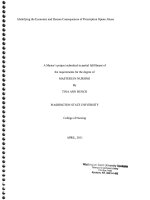
Figure 1 shows a typical application circuit for biasing a GaAs PA
in a cellular subscriber unit’s transmitter. Each key component of
the circuit is described below.
INTRODUCTION
RF bandwidths for cellular systems such as AMPS, TACS, GSM,
TDMA, and CDMA range from 800MHz to 1.0GHz. To provide RF
transmissions over this range of frequencies, Gallium Arsenide
(GaAs) has become the technology of choice and offers several
advantages over silicon technology: a much higher cutoff frequency, higher breakdown voltage, lower noise figure, and higher
power-added efficiency. This translates to lower power dissipation
and longer talk time for cellular subscribers.
To properly bias a GaAs Power Amplifier (PA), a negative DC bias
is required. There are many methods for providing this DC bias, but
in a majority of applications, a regulated bias scheme is desirable
over an unregulated inverting charge pump.
Single Cell Li-Ion Battery and High-Side FET Switch
The main power source of this circuit is a single +3.6V Lithium Ion
(Li-Ion) cell. Commercial packs using this battery chemistry can
have a voltage as high as +4.2V or as low as +2.8V. This circuit will
work under any condition within this range. Digital wireless standards such as TDMA and CDMA tend to operate the transmit
section in “burst mode,” switching the PA circuit off most of the time.
Consequently, a digitally controlled power switch is included. The
main requirements of this switch are: TTL/CMOS compatible
control input, low “on” resistance, and high-side switching capability. “TX_ENABLE” signifies the power switch control signal, and is
generated in the subscriber unit’s modem controller.
Antenna
RFIN GaAs Power
Amplifier
TX_ENABLE
(from Modem
Controller)
Li-Ion +
Battery
(+3.6V)
PA_BIAS_ENABLE
(from Modem
Controller)
C1
0.47µF
C2
0.47µF
+
CIN
4.7µF
RFOUT
VD1
VD2
VG1
Duplexer
GND
VG2
VIN
CCLK
C1+
C1–
C2+
C2–
PA_BIAS_ENABLE Negative
DC bias
stabilization
time
TX_ENABLE
CTL
High-Side
IN N-Channel OUT
FET Switch
GND
TC1142-50
–5.0V
VOUT
+
GND
Inductorless Boost/Buck
Regulator
COUT
4.7µF
Note: Modem Controller must not
enable the High-Side N-Channel FET
switch (via TX_ENABLE) until the
negative bias supply is stable
(per Timing Diagram)
Transmit RF
Negative
DC bias still
stable after
Transmit RF
completion
FIGURE 1: Application circuit for biasing a GaAs power amplifier in a cellular subscriber unit's transmitter.
© 2002 Microchip Technology Inc.
DS00808A-page 1
AN808
Regulated Voltage Inverter
The inductorless voltage inverter is the core of the negative DC bias
generator. It is a switched capacitor (charge pump) voltage converter, and the two 0.47µF flying capacitors (C1, C2) and the 4.7µF
output capacitor (COUT) are the only external components required.
The output current is a function of the C1, C2 flying capacitors, and
the output ripple voltage magnitude is dependent on C1, C2, and
COUT. The output ripple waveform is superimposed on the nominal
–5.0VDC and has a fundamental frequency of 200KHz.
“PA_BIAS_ENABLE” is the power control signal for the regulated
negative bias generator from the subscriber unit’s modem controller. Timing requirements for this signal versus “TX_ENABLE” are
shown in Figure 1.
Previously, many designers have chosen a switching regulator for
this circuit application, however the TC1142 has altered this
approach. Since switching regulators require inductors, they
increase the installed size, generated noise, and cost of providing
this negative DC bias requirement. The TC1142 provides a “boost/
buck” regulated conversion from either a single-cell Li-Ion, a multicell Nickel Cadmium (NiCd), or a multi-cell Nickel Metal Hydride
(NiMH) battery pack. Figure 2 shows a simple block diagram of the
TC1142 Inductorless Boost/Buck regulator architecture. The
TC1142 can be ordered to provide output voltages from –3.0V to
–5.0V in 1.0V increments.
VIN = 2.5V to 5.5V
C1+
Charge
Pump
Switches
Shutdown
CCLK
Clock
Circuit
C1–
OSC
Override
VOUT
–
Reference
Voltage
R1
+
+
COUT
R2
–
1.2V
FIGURE 2: TC1142 architecture.
Circuit Description of Inductorless Boost/Buck Regulator
Ordinary charge pumps simply "convert" (not regulate) their input
voltages. For example, a TC7660 charge pump generates a noload output voltage of –5V when VIN = +5V. However, its output
voltage falls with a corresponding decrease in input voltage, an
increase in output current, or both.
DS00808A-page 2
In order to maintain the lowest output resistance and output ripple
voltage, it is recommended that low equivalent series resistance
(ESR) capacitors be used. Additionally, larger values of the output
capacitor and lower values of the flying capacitors will reduce the
output voltage ripple.
Depending on the maximum voltage ripple allowed, the TC1142
will provide more-than-adequate regulation for most portable applications. Table 1 shows the relationship between output voltage
ripple versus the two flying capacitors (C1 and C2) and the output
capacitor (COUT). In each case, a 3.2V input is being converted to
a –5V output.
Assuming the output is loaded to at least 20% of the maximum
available current, the power efficiency of the inductorless boost/
buck regulator can be estimated as the absolute value of the
regulated voltage, divided by twice the input voltage. Thus, for a
3.6V battery input generating a –5V output, the efficiency of the
inductorless boost/buck regulator will be approximately 70%.
C2+
C2–
ERROR
Comparator
+
The TC1142 differs in that it uses pulse-frequency modulation
(PFM) control to generate a regulated output voltage without the
use of a post linear regulator. The TC1142 consists of an inverting/
doubling charge pump and a feedback circuit (sampling resistors
R1, R2, ERROR comparator, and associated voltage reference).
When operating at full clock speed, the charge pump generates an
unregulated output voltage equal to –2VIN. The ERROR comparator inhibits operation of this charge pump (i.e. skips clock pulses)
whenever the output voltage sampled by R1 and R2 is more
negative than the reference voltage. The combination of the
doubling pump and feedback regulation allows the absolute value
of VOUT to be regulated above or below that of VIN. The TC1142
delivers an output voltage of –5V at a maximum of 20 mA over an
input voltage range of +2.5V to +5.5V.
C1, C2
(µF)
COUT
(µF)
VIN
(V)
VOUT
(V)
VRIPPLE
(mV)
0.01
0.22
0.33
0.47
0.68
1.0
0.1
0.22
0.33
0.47
0.68
1.0
4.7
4.7
4.7
4.7
4.7
4.7
10
10
10
10
10
10
3.2
3.2
3.2
3.2
3.2
3.2
3.2
3.2
3.2
3.2
3.2
3.2
–5
–5
–5
–5
–5
–5
–5
–5
–5
–5
–5
–5
14.6
31.4
46.1
63.9
88.7
123.2
7.0
15.1
22.4
31.5
44.7
63.8
TABLE 1: Voltage ripple vs. C1/C2 flying capacitors and output
capacitor C OUT. ESR = 0.1Ω, I OUT = 20mA.
© 2002 Microchip Technology Inc.
AN808
GaAs PA, Duplexer, and Antenna
SUMMARY
The GaAs PA radiates RF energy through a tuned bandpass filter
(i.e. duplexer) to the subscriber unit’s antenna port. Depending
on the cellular standard and the power class of the subscriber
unit, different power levels are required of GaAs PAs. For
instance, a Class III AMPS subscriber unit must be able to radiate
a minimum power level of +28dBm through the antenna. A CDMA
Class III subscriber unit, in comparison, has a lower minimum
power level requirement of +23dBm. Since the GaAs PA must be
able to efficiently meet these industry standard power requirements, the RF losses in the duplexer must also be considered in
the design of the PA.
GaAs has become the technology of choice over silicon in cellular
telephone power amplifier applications. With GaAs technology,
lower noise figures, higher cutoff frequencies, and higher poweradded efficiency allow the cellular user increased talk time as
compared to silicon PAs.
© 2002 Microchip Technology Inc.
GaAs PAs require a negative DC bias, and the TC1142 offers
significant advantages over inductor-based switchers or unregulated charge pumps: lower generated noise; smaller installed size;
lower installed cost; and excellent output regulation for subscriber
units which operate in most existing worldwide cellular standards.
DS00808A-page 3
AN808
NOTES:
DS00808A-page 4
2002 Microchip Technology Inc.
Information contained in this publication regarding device
applications and the like is intended through suggestion only
and may be superseded by updates. It is your responsibility to
ensure that your application meets with your specifications.
No representation or warranty is given and no liability is
assumed by Microchip Technology Incorporated with respect
to the accuracy or use of such information, or infringement of
patents or other intellectual property rights arising from such
use or otherwise. Use of Microchip’s products as critical components in life support systems is not authorized except with
express written approval by Microchip. No licenses are conveyed, implicitly or otherwise, under any intellectual property
rights.
Trademarks
The Microchip name and logo, the Microchip logo, FilterLab,
KEELOQ, microID, MPLAB, PIC, PICmicro, PICMASTER, PICSTART, PRO MATE, SEEVAL and The Embedded Control Solutions Company are registered trademarks of Microchip
Technology Incorporated in the U.S.A. and other countries.
dsPIC, ECONOMONITOR, FanSense, FlexROM, fuzzyLAB,
In-Circuit Serial Programming, ICSP, ICEPIC, microPort,
Migratable Memory, MPASM, MPLIB, MPLINK, MPSIM,
MXDEV, PICC, PICDEM, PICDEM.net, rfPIC, Select Mode
and Total Endurance are trademarks of Microchip Technology
Incorporated in the U.S.A.
Serialized Quick Turn Programming (SQTP) is a service mark
of Microchip Technology Incorporated in the U.S.A.
All other trademarks mentioned herein are property of their
respective companies.
© 2002, Microchip Technology Incorporated, Printed in the
U.S.A., All Rights Reserved.
Printed on recycled paper.
Microchip received QS-9000 quality system
certification for its worldwide headquarters,
design and wafer fabrication facilities in
Chandler and Tempe, Arizona in July 1999. The
Company’s quality system processes and
procedures are QS-9000 compliant for its
PICmicro® 8-bit MCUs, KEELOQ® code hopping
devices, Serial EEPROMs and microperipheral
products. In addition, Microchip’s quality
system for the design and manufacture of
development systems is ISO 9001 certified.
2002 Microchip Technology Inc.
DS00808A - page 5
M
WORLDWIDE SALES AND SERVICE
AMERICAS
ASIA/PACIFIC
Corporate Office
Australia
2355 West Chandler Blvd.
Chandler, AZ 85224-6199
Tel: 480-792-7200 Fax: 480-792-7277
Technical Support: 480-792-7627
Web Address:
Microchip Technology Australia Pty Ltd
Suite 22, 41 Rawson Street
Epping 2121, NSW
Australia
Tel: 61-2-9868-6733 Fax: 61-2-9868-6755
Rocky Mountain
China - Beijing
2355 West Chandler Blvd.
Chandler, AZ 85224-6199
Tel: 480-792-7966 Fax: 480-792-7456
Microchip Technology Consulting (Shanghai)
Co., Ltd., Beijing Liaison Office
Unit 915
Bei Hai Wan Tai Bldg.
No. 6 Chaoyangmen Beidajie
Beijing, 100027, No. China
Tel: 86-10-85282100 Fax: 86-10-85282104
Atlanta
500 Sugar Mill Road, Suite 200B
Atlanta, GA 30350
Tel: 770-640-0034 Fax: 770-640-0307
Boston
2 Lan Drive, Suite 120
Westford, MA 01886
Tel: 978-692-3848 Fax: 978-692-3821
Chicago
333 Pierce Road, Suite 180
Itasca, IL 60143
Tel: 630-285-0071 Fax: 630-285-0075
Dallas
4570 Westgrove Drive, Suite 160
Addison, TX 75001
Tel: 972-818-7423 Fax: 972-818-2924
Detroit
Tri-Atria Office Building
32255 Northwestern Highway, Suite 190
Farmington Hills, MI 48334
Tel: 248-538-2250 Fax: 248-538-2260
Kokomo
2767 S. Albright Road
Kokomo, Indiana 46902
Tel: 765-864-8360 Fax: 765-864-8387
Los Angeles
18201 Von Karman, Suite 1090
Irvine, CA 92612
Tel: 949-263-1888 Fax: 949-263-1338
China - Chengdu
Microchip Technology Consulting (Shanghai)
Co., Ltd., Chengdu Liaison Office
Rm. 2401, 24th Floor,
Ming Xing Financial Tower
No. 88 TIDU Street
Chengdu 610016, China
Tel: 86-28-6766200 Fax: 86-28-6766599
China - Fuzhou
Microchip Technology Consulting (Shanghai)
Co., Ltd., Fuzhou Liaison Office
Unit 28F, World Trade Plaza
No. 71 Wusi Road
Fuzhou 350001, China
Tel: 86-591-7503506 Fax: 86-591-7503521
China - Shanghai
Microchip Technology Consulting (Shanghai)
Co., Ltd.
Room 701, Bldg. B
Far East International Plaza
No. 317 Xian Xia Road
Shanghai, 200051
Tel: 86-21-6275-5700 Fax: 86-21-6275-5060
China - Shenzhen
150 Motor Parkway, Suite 202
Hauppauge, NY 11788
Tel: 631-273-5305 Fax: 631-273-5335
Microchip Technology Consulting (Shanghai)
Co., Ltd., Shenzhen Liaison Office
Rm. 1315, 13/F, Shenzhen Kerry Centre,
Renminnan Lu
Shenzhen 518001, China
Tel: 86-755-2350361 Fax: 86-755-2366086
San Jose
Hong Kong
Microchip Technology Inc.
2107 North First Street, Suite 590
San Jose, CA 95131
Tel: 408-436-7950 Fax: 408-436-7955
Microchip Technology Hongkong Ltd.
Unit 901-6, Tower 2, Metroplaza
223 Hing Fong Road
Kwai Fong, N.T., Hong Kong
Tel: 852-2401-1200 Fax: 852-2401-3431
New York
Toronto
6285 Northam Drive, Suite 108
Mississauga, Ontario L4V 1X5, Canada
Tel: 905-673-0699 Fax: 905-673-6509
India
Microchip Technology Inc.
India Liaison Office
Divyasree Chambers
1 Floor, Wing A (A3/A4)
No. 11, O’Shaugnessey Road
Bangalore, 560 025, India
Tel: 91-80-2290061 Fax: 91-80-2290062
Japan
Microchip Technology Japan K.K.
Benex S-1 6F
3-18-20, Shinyokohama
Kohoku-Ku, Yokohama-shi
Kanagawa, 222-0033, Japan
Tel: 81-45-471- 6166 Fax: 81-45-471-6122
Korea
Microchip Technology Korea
168-1, Youngbo Bldg. 3 Floor
Samsung-Dong, Kangnam-Ku
Seoul, Korea 135-882
Tel: 82-2-554-7200 Fax: 82-2-558-5934
Singapore
Microchip Technology Singapore Pte Ltd.
200 Middle Road
#07-02 Prime Centre
Singapore, 188980
Tel: 65-6334-8870 Fax: 65-6334-8850
Taiwan
Microchip Technology Taiwan
11F-3, No. 207
Tung Hua North Road
Taipei, 105, Taiwan
Tel: 886-2-2717-7175 Fax: 886-2-2545-0139
EUROPE
Denmark
Microchip Technology Nordic ApS
Regus Business Centre
Lautrup hoj 1-3
Ballerup DK-2750 Denmark
Tel: 45 4420 9895 Fax: 45 4420 9910
France
Microchip Technology SARL
Parc d’Activite du Moulin de Massy
43 Rue du Saule Trapu
Batiment A - ler Etage
91300 Massy, France
Tel: 33-1-69-53-63-20 Fax: 33-1-69-30-90-79
Germany
Microchip Technology GmbH
Gustav-Heinemann Ring 125
D-81739 Munich, Germany
Tel: 49-89-627-144 0 Fax: 49-89-627-144-44
Italy
Microchip Technology SRL
Centro Direzionale Colleoni
Palazzo Taurus 1 V. Le Colleoni 1
20041 Agrate Brianza
Milan, Italy
Tel: 39-039-65791-1 Fax: 39-039-6899883
United Kingdom
Arizona Microchip Technology Ltd.
505 Eskdale Road
Winnersh Triangle
Wokingham
Berkshire, England RG41 5TU
Tel: 44 118 921 5869 Fax: 44-118 921-5820
03/01/02
*DS40232E*
DS40232E-page 44
2002 Microchip Technology Inc.