AN0822 stepper motor microstepping with PIC18C452
Bạn đang xem bản rút gọn của tài liệu. Xem và tải ngay bản đầy đủ của tài liệu tại đây (468.93 KB, 58 trang )
M
AN822
Stepper Motor Microstepping with PIC18C452
Authors:
STEPPER MOTOR BASICS
Padmaraja Yedamale
Sandip Chattopadhyay
Microchip Technology Inc.
Now let’s take a closer look at a stepper motor. The first
thing that we notice is that it has more than two wires
leading into it. In fact, various versions have four, five,
six, and sometimes more wires. Also, when we manually rotate the shaft, we get a ‘notched’ feeling. The simplest way to think about a stepper motor is as a bar
magnet that pivots about its center with four individual,
but exactly identical electromagnets, as shown in
Figure 1A. If we manually rotate the magnet without
energizing any coils, we get the ‘notched’ feeling whenever a relatively larger magnetic force is generated,
because of the alignment of the permanent magnet
with the core of the electromagnets, as in Figure 1A.
This force is termed ‘detent torque’. Let’s assume that
the initial position of the magnetic rotor is as shown in
Figure 1A. Now turn on coil A; i.e., flow current through
it to create an electromagnet, as shown in Figure 1B.
The motor does not rotate, but we cannot move it freely
by hand (more torque has to be applied to move it now),
because of a larger ‘holding torque’. This torque is generated by the attraction of the north and south poles of
the rotor magnet and the electromagnet produced in
the stator by the current.
INTRODUCTION
A stepper motor, as its name suggests, moves one step
at a time, unlike those conventional motors, which spin
continuously. If we command a stepper motor to move
some specific number of steps, it rotates incrementally
that many number of steps and stops. Because of this
basic nature of a stepper motor, it is widely used in low
cost, open loop position control systems. Open loop
control means no feedback information about the position is needed. This eliminates the need for expensive
sensing and feedback devices, such as optical encoders. Motor position is known simply by keeping track of
the number of input step pulses.
FIGURE 1:
NON-ENERGIZED AND CLOCKWISE CURRENT IN COIL A
A
B
A
A
S
N
D
N
B
B
S
S
C
C
NON-ENERGIZED
2002 Microchip Technology Inc.
D
CLOCKWISE CURRENT IN COIL A
DS00822A-page 1
AN822
FIGURE 2:
FIRST STEP MOVEMENT AND NEXT STEP
A
B
A
A
S
D
S
N
S
B
D
B
N
S
C
FIRST STEP
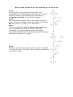
To move the motor in a clockwise direction from its initial stop position, we need to generate torque in the
clockwise direction. This is done by turning off coil A,
and turning on coil B. The electromagnet in coil B pulls
the magnetized rotor and the rotor aligns itself with coil
B, as shown in Figure 2A. Turning off coil B and turning
on coil C will move the rotor one step further, as shown
in Figure 2B.
C
COUNTER-CLOCKWISE CURRENT IN COIL C
A 360 degree rotation of the rotor will be completed if
you turn off coil D and turn on coil A. The coil operation
sequence (B, C, D, A), described is responsible for the
clockwise rotation of the motor. The rotor will move
counter-clockwise from its initial position at Figure 1B if
we follow the opposite sequence (D, C, B, A).
Comparing Figure 1B and Figure 2B, we understand
that the direction of current flow in coil C is exactly
opposite to the direction of flow in coil A. This is
required to generate an electromagnet of correct polarity, which will pull the rotor in the clockwise direction. By
the same logic, the direction of current in coil D will be
opposite to coil B when the rotor takes the next step
(due to turning off coil C and turning on coil D).
DS00822A-page 2
2002 Microchip Technology Inc.
AN822
UNIPOLAR AND BIPOLAR
Two leads on each of the four coils of a stepper motor
can be brought out in different ways. All eight leads can
be taken out of the motor separately. Alternatively, connecting A and C together, and B and D together, as
shown in Figure 3, can form two coils. Leads of these
two windings can be brought out of the motor in three
different ways, as shown in Figure 3, Figure 4, and
Figure 5.
If the coil ends are brought out as shown in Figure 3,
then the motor is called a bipolar motor, and if the wires
are brought out as shown in Figure 4 or Figure 5, with
one or two center tap(s), it is called a unipolar motor.
FIGURE 3:
AN ACTUAL PERMANENT MAGNET
(PM) STEPPER MOTOR
The simple stepper motor described, moves in very
coarse steps of 90 degrees. How do actual motors
achieve movements as low as 7.5 degrees? The stator
(the stationary electromagnets) of a real motor has
more segments on it. A typical stator arrangement with
eight stators is shown in Figure 6.
FIGURE 6:
STATOR WINDING
ARRANGEMENTS IN A
PERMANENT MAGNET
STEPPER MOTOR
BIPOLAR (4-WIRE)
45°
60°
A
1
A
15°
2
C
H
3
B
D
B
4
N
G
S
S
N
N
C
S
FIGURE 4:
UNIPOLAR (5-WIRE)
D
F
1
3
A
2
C
B
D
4
5
FIGURE 5:
UNIPOLAR (6-WIRE)
3
E
The rotor is also different and a typical cylindrical rotor
with 6 poles is shown in Figure 6. There are 45 degrees
between each stator section and 60 degrees between
each rotor pole. Using the principle of vernier mechanism, the actual movement of the rotor for each step is
60 minus 45 or 15 degrees. In this case, also, there are
only two coils: one connects pole sections A, C, E and
G, and the other connects B, D, F, H. Let us assume
that current is flowing in a certain direction through the
first coil only, and pole sections are wired in such a
fashion that:
• A and C have S-polarity
• E and G have N-polarity
1
A
C
4
B
D
2
5
The rotor will be lined up accordingly, as shown in
Figure 6. Let’s say that we want the rotor to move 15
degrees clockwise. We would remove the current
applied to the first winding and energize the second
winding. The pole sections B, D, F, H are wired together
with the second winding in such a way that:
• B and D have S-polarity
• F and H have N-polarity
6
2002 Microchip Technology Inc.
DS00822A-page 3
AN822
In the next step, current through winding 2 is removed
and reverse polarity current is applied in winding 1.
This time A and C have N-polarity, and E and G have
S-polarity; so the rotor will take a further 15 degree step
in the clockwise direction. The principle of operation is
the same as the basic stepper motor with a bar magnet
as rotor and four individual electromagnets as stators,
but in this construction, 15 degrees per step is
achieved. Different ’step angles’ (i.e., angular displacement in degrees per step) can be obtained by varying
the design with different numbers of stators and rotor
poles. In an actual motor, both rotor and stators are
cylindrical, as shown in Figure 7. This type of motor is
called a permanent magnet (PM) stepper because the
rotor is a permanent magnet. These are low cost
motors with typical step angles of 7.5 degrees to 15
degrees.
VARIABLE RELUCTANCE (VR)
STEPPER MOTOR
There is a type of motor where the rotor is not cylindrical, but looks like bars with a number of teeth on it, as
shown in Figure 8. The rotor teeth are made of soft
iron. The electromagnet produced by activating stator
coils in sequence, attracts the metal bar (rotor) towards
the minimum reluctance path in the magnetic circuit.
We don’t get a notched feeling when we try to rotate it
manually in the non-energized condition. In the
non-energized condition, there is no magnetic flux in
the air gap, as the stator is an electromagnet and the
rotor is a piece of soft iron; hence, there is no detent
torque. This type of stepper motor is called a variable
reluctance stepper (VR). The motor shown in Figure 8
has four rotor teeth, 90 degrees apart and six stator
poles, 60 degrees apart. So when the windings are
energized in a reoccurring sequence of 2, 3, 1, and so
on, the motor will rotate in a 30 degree step angle.
These motors provide less holding torque at standstill
compared to the PM type, but the dynamic torque characteristics are better.
Variable reluctance motors are normally constructed
with three or five stator windings, as opposed to the two
windings in the PM motors.
FIGURE 7:
A BIPOLAR PERMANENT MAGNET STEPPER MOTOR
Permanent Magnet
Rotor
Stator Winding
FIGURE 8:
A VARIABLE RELUCTANCE MOTOR
Soft Iron Rotor
Stator Winding
DS00822A-page 4
2002 Microchip Technology Inc.
AN822
HYBRID (HB) STEPPER MOTOR
Construction of permanent magnet motors becomes
very complex below 7.5 degrees step angles. Smaller
step angles can be realized by combining the variable
reluctance motor and the permanent magnet motor
principles. Such motors are called hybrid motors (HB),
which give much smaller step angles, as small as 0.9
degrees per step.
A typical hybrid motor is shown in Figure 9. The stator
construction is similar to the permanent magnet motor,
and the rotor is cylindrical and magnetized like the PM
motor with multiple teeth like a VR motor. The teeth on
the rotor provide a better path for the flux to flow
through the preferred locations in the air gap. This
increases the detent, holding, and dynamic torque
characteristics of the motor compared to the other two
types of motors.
Hybrid motors have a smaller step angle compared to
the permanent magnet motor, but they are very expensive. In low cost applications, the step angle of a permanent magnet motor is divided into smaller angles
using better control techniques.
Permanent magnet motors and hybrid motors are more
popular than the variable reluctance motor, and since
the stator construction of these motors is very similar, a
common control circuit can easily drive both types of
motors.
FIGURE 9:
HOW TO IDENTIFY THE PERMANENT
MAGNET/HYBRID MOTOR LEADS
The color code of the wires coming out of the motor are
not standard; however, using a multimeter/ohmmeter, it
is easy to identify the winding ends and center tap.
If only four leads are coming out of the motor, then the
motor is a bipolar motor. If the resistance measured
across two terminals, say terminals 1 and 2 in Figure 3,
is finite, then those are ends of a coil. If the multimeter
shows an open circuit (i.e., if you are trying to measure
across the terminals 1 and 3, or 1 and 4, or 2 and 3, or
2 and 4), then the terminals are of different windings.
Change your lead to another terminal and check again
to find a finite resistance.
If there are five leads coming out of the motor, then the
resistance across one terminal and all other terminals
will be almost equal. This common terminal is the center tap and the other terminals are the ends of different
windings. Figure 4 shows terminal 5 is the common terminal, while 1, 2, 3, and 4 are the ends of the windings.
In the case of a motor with six leads as in Figure 5,
resistance across terminals 1 and 2 should be approximately double the resistance measured across terminals 1 and 3, and 2 and 3. The same is applicable for
the other winding (the remaining 3 wires).
In all the above cases, once the terminals are identified, it is important to know the sequence in which the
windings should be energized. This is done by energizing the terminals one after the other, by rated voltage.
If the motor smoothly moves in a particular direction,
say clockwise, when the windings are energized, then
the energizing sequence is correct. If the motor hunts
or moves in a jerky manner, then the sequence of winding segments has to be changed and checked again for
smooth movement.
CONSTRUCTION OF A HYBRID MOTOR
Permanent magnet
rotor with teeth
S
N
N
S
S
N
Stator Winding
2002 Microchip Technology Inc.
DS00822A-page 5
AN822
TORQUE AND SPEED
constant is less. With a lower time constant, current rise
in the coil will be faster, which enables a higher
step-rate. Using a Resistance-Inductance (RL) drive
can achieve a higher step rate in motors with higher
inductance, which is discussed in the next section.
The speed of a stepper motor depends on the rate at
which you turn on and off the coils, and is termed the
’step-rate’. The maximum step-rate, and hence, the
maximum speed, depends upon the inductance of the
stator coils. Figure 10 shows the equivalent circuit of a
stator winding and the relation between current rise
and winding inductance. It takes a longer time to build
the rated current in a winding with greater inductance
compared to a winding with lesser inductance. So,
when using a motor with higher winding inductance,
sufficient time needs to be given for current to build up
before the next step command is issued. If the time
between two step commands is less than the current
build-up time, it results in a ’slip’, i.e., the motor misses
a step. Unfortunately, the inductance of the winding is
not well documented in most of the stepper motor data
sheets. In general, for smaller motors, the inductance
of the coil is much less than its resistance, and the time
FIGURE 10:
The best way to decide the maximum speed is by
studying the torque vs. step-rate (expressed in pulse
per second or pps) characteristics of a particular stepper motor (shown in Figure 11). ’Pull-in’ torque is the
maximum load torque that the motor can start or stop
instantaneously without mis-stepping. ’Pull-out’ torque
is the torque available when the motor is continuously
accelerated to the operating point. From the graph, we
can conclude that for this particular motor, the ‘maximum self-starting frequency’ is 200 pps. The term
‘maximum self-starting frequency’ is the maximum
step-rate at which the motor can start instantaneously
at no-load without mis-stepping. While at no-load, this
motor can be accelerated up to 275 pps.
MOTOR EQUIVALENT CIRCUIT AND CURRENT RISE RATE IN STATOR WINDING
R
V
IMAX
Lower
Inductance
Motor
Equivalent
Circuit
+
-
Higher
Inductance
Current
L
REXT
Time
FIGURE 11:
A TYPICAL SPEED VS. TORQUE CURVE
Torque in-oz
Pull-out torque
Pull-in torque
0
200
DS00822A-page 6
275
Step-rate in pps
2002 Microchip Technology Inc.
AN822
DRIVE CIRCUITS
As the rating of the motor increases, the winding inductance also increases. This higher inductance results in
a sluggish current rise in the windings, which limits the
step-rate, as explained in the previous section. We can
reduce the time constant by externally adding a suitable resistor in series with the coil and applying more
than the rated voltage. The resistor should be chosen
in such a way that the voltage across the coil does not
exceed the rated voltage, and the additional voltage is
dropped across the resistor. This method is also useful
if we have a fixed power supply with an output of more
than the rated coil-voltage specified. This type of drive
is called a resistance-inductive (RL) drive. Electronic
circuitry can be added to vary this resistor value
dynamically to get the best result. The main disadvantage of this drive is that, since they are used with
motors with large torque ratings, current flowing
through the series resistor is large, resulting in higher
heat dissipation and, hence, the size of the drive
becomes bulky.
The drive mechanism for 5-wire and 6-wire unipolar
motors is fairly simple and is shown in Figure 12 (A and
B). Only one coil is shown in this figure, but the other
will be connected in the same way.
By comparing Figure 12A and Figure 12B, we see the
direction of current flow is opposite in sections A and C
of the coil, as per our explanation earlier. But the current flow in a particular section of the coil is always unidirectional, hence the name ‘unipolar motor’.
Bipolar stepper motors do not have the center tap. That
makes the motor construction easier, but it needs a different type of driver circuit, which reverses the current
flow through the entire coil by alternating the polarity of
the terminals, giving us the name ‘bipolar’.
A bipolar motor is capable of higher torque since the
entire coil is energized, not just half. Let’s look at the
mechanism for reversing the voltage across one of the
coils, as shown in Figure 13.
This resistor can be avoided by using PWM current
control in the windings. In PWM control, current
through the winding can be controlled by modulating
the ‘ON’ time and ‘OFF’ time of the switches with PWM
pulses, thus ensuring that only the required current
flows through the coil, as shown in Figure 14.
This circuit is called an H-bridge, because it resembles
a letter ‘H’. The current can be reversed through the
coil by closing the appropriate switches. If switches A
and D are closed, then current flows in one direction,
and if switches B and C are closed, then current flows
in the opposite direction.
FIGURE 12:
SIMPLIFIED DRIVES FOR THE UNIPOLAR MOTOR
A
B
Supply
A
Supply
C
A
ONE STEP MOVEMENT
FIGURE 13:
C
COUNTER-CLOCKWISE CURRENT IN COIL C
SIMPLIFIED H-BRIDGE CONFIGURATION
+Supply
C
A
Control
B
2002 Microchip Technology Inc.
D
DS00822A-page 7
AN822
FIGURE 14:
ton
CURRENT WAVE FORM WITH
PWM SWITCHING
FIGURE 15:
BLOCK DIAGRAM OF FULL
STEP CONTROL
toff
V
RB2
PWM
RB3
Time
PIC18C452 RB4
Winding A
Motor
Driver
RB5
Current
Winding B
Time
STEPPER MOTOR CONTROL
To control a stepper motor, we need a proper driver circuit as discussed earlier. Unipolar drive can be used
with unipolar motors only. In this application note, a
bipolar drive is discussed, as this can be used to control both bipolar and unipolar motors. Unipolar motors
can be connected to a bipolar driver by simply ignoring
the center taps (by doing this, the motor becomes bipolar). Next we need a sequencer to issue proper signals
in a required sequence to the H-bridges. A controller is
built around the PIC18C452. Two H-bridges are used
to control two windings of the stepper motors. Functional block diagram is shown in Figure 15. Example 1
shows the code required for full step control written for
PIC18C452:
Code which configures PORTB<5:2> as output pins is
not given in the example.
The code makes RB<5:2> outputs either ‘0’ or ‘1’
sequentially, which switches off or applies positive (+)
or negative (-) polarity to Winding A and Winding B, as
shown below:
Winding A
+
0
step 1
0
+
step 2
-
0
step 3
0
-
step 4
Legend:
• 0 = coil OFF
• + = current flows in one direction
• - = current flows in the opposite direction
Note:
DS00822A-page 8
Winding B
Step 1 follows after step 4 and the cycle
continues.
2002 Microchip Technology Inc.
AN822
EXAMPLE 1:
#define
#define
#define
#define
clrf
FULL STEP WITH ‘ONE PHASE ON’ AT A TIME
STEP_ONE
STEP_TWO
STEP_THREE
STEP_FOUR
b’00100000’
b’00010000’
b’00001000’
b’00000100’
STEP_NUMBER
; PortB<5:2> are used to connect the
; switches
; Initialize start of step sequence
;***********************************************************************
Initialize here TMR0 module, enable TMR0 interrupt and load a value in TMR0
;***********************************************************************
;************************************************************************
; Routine in TMR0 ISR which updates the current sequence for the next steps
;************************************************************************
org
2000h
UPDATE_STEP
incf
STEP_NUMBER,F
; Increment step number
btfsc
STEP_NUMBER,2
; If Step number = 4h then clear the count
clrf
STEP_NUMBER
movf
STEP_NUMBER,W
; Load the step number to Working register
call
OUTPUT_STEP
; Load the sequence from the table
movwf
PORTB
; to Port B
return
OUTPUT_STEP
addwf
PCL,F
; Add Wreg content to PC and
retlw
STEP_ONE
; return the corresponding sequence in Wreg
retlw
STEP_TWO
retlw
STEP_THREE
retlw
STEP_FOUR
The step command sequence is updated in the Timer0
overflow Interrupt Service Routine. After issuing each
step command in the sequence, PIC18C452 waits for
the Timer 0 overflow interrupt to issue the next step
sequence. This waiting time can be programmed by
loading different values in the TMR0 register. Motor
speed depends upon this value in the TMR0 register.
Instead of creating a software delay loop, Timer 0 module of PIC18C452 is loaded with an appropriate value
to interrupt the processor every 1/96 second. Steps are
updated in the Timer 0 Interrupt Service Routine. By
loading different values in the Timer 0 module, the
speed of the motor can be changed. The current
through the two coils looks like a wave, as shown in
Figure 16, so this is termed ‘wave drive’.
EQUATION 1:
This controller drives current through only one winding
at a given time, so it is also termed ‘One Phase On
control’. This is the simplest kind of controller. The
torque generated in this mode is less, as only one winding at a time is used. For the same stepper motor, we
can improve the torque characteristics, by designing a
better controller and thereby improving the drive
capability.
CALCULATE STEP
COMMAND WAITING
PERIOD
No. Steps per Revolution = 360/Motor Step Angle
pps = (rpm/60) * No. Steps per Revolution
Twait = 1/pps
For example, to turn a PM motor with a 7.5 degree step
angle at a speed of 120 revolutions per minute (rpm),
96 pulses per second (pps) is required. This means
that the waiting period should be 1/96 second to
achieve this speed.
2002 Microchip Technology Inc.
The following are the most common drive types:
• ‘Two Phase On’ full step drive
• Half step drive, where the motor moves half of the
full step angle (7.5/2 degrees in the case of a motor
with 7.5 degrees of step angle)
• Microstepping (which requires unequal current flow
in two windings), where the rotor moves a fraction of
the full step angle (1/4, 1/8, 1/16 or 1/32).
DS00822A-page 9
AN822
FIGURE 16:
FULL STEP ‘ONE PHASE ON’ OR WAVE CONTROL
+
Winding A
+
Winding B
1
2
3
4
1
2
Steps
‘TWO PHASE ON’ FULL STEPPING
In this method, both windings of the motor are always
energized. Instead of making one winding off and
another on, in sequence, only the polarity of one winding at a time is changed as shown:
Winding A:
+
-
-
+
+ …
Winding B:
+
+
-
-
+ …
EXAMPLE 2:
#define
#define
#define
#define
clrf
The code written for ‘One Phase On’ control is modified, as shown below in Example 2, to achieve ‘Two
Phase On’ control.
The UPDATE_STEP function is the same as in
Example 1, but in the OUTPUT_STEP function, two
steps are AND’d (i.e., simultaneously two outputs of
port B are ‘1’), which makes the two coils ‘ON’ simultaneously. The energizing sequence for both windings is
shown in Figure 17.
‘TWO PHASE ON’ CONTROL
STEP_ONE
STEP_TWO
STEP_THREE
STEP_FOUR
b’00100000’
b’00010000’
b’00001000’
b’00000100’
STEP_NUMBER
; PortB<5:2> are used to connect the
; switches
; Initialize start of step sequence
;***********************************************************************
Initialize here TMR0 module, enable TMR0 interrupt and load a value in TMR0
;***********************************************************************
;**************************************************************************
; Routine in ISR which updates the current sequence for the next steps
;**************************************************************************
org
2000h
UPDATE_STEP
incf
STEP_NUMBER,F
; Increment step number
btfsc
STEP_NUMBER,2
; If Step number = 4h then clear the count
clrf
STEP_NUMBER
movf
STEP_NUMBER,W
; Load the step number to Working register
call
OUTPUT_STEP
; Load the sequence from the table
movwf
PORTB
; to PortB
return
OUTPUT_STEP
addwf
PCL,F
retlw
STEP_ONE | STEP_TWO
retlw
STEP_TWO | STEP_THREE
retlw
STEP_THREE | STEP_FOUR
retlw
STEP_FOUR | STEP_ONE
DS00822A-page 10
; Add Wreg content to PC and
; return the corresponding sequence in Wreg
2002 Microchip Technology Inc.
AN822
FIGURE 17:
VOLTAGE SEQUENCE WITH ‘TWO PHASE ON’ AT A TIME
+
Winding A
+
Winding B
1
2
3
4
1
2
3
4
Steps
FIGURE 18:
MOTOR ROTATION SEQUENCE WITH ‘TWO PHASE ON’ AT A TIME
With the current flowing in both windings simultaneously, the rotor aligns itself between the ‘average
north’ and ‘average south’ magnetic poles, as shown in
Figure 18. Since both phases are always ‘ON’, this
method gives 41.4 percent more torque than ‘One
Phase On’ stepping.
2002 Microchip Technology Inc.
One drawback of a stepper motor is that it has a natural
resonant frequency. When the step-rate equals this frequency, we experience an audible change in the noise
made by the motor, as well as an increase in vibration.
The resonance point varies with the application and
load, and typically occurs at low speed. In severe
cases, the motor may lose steps at the resonant frequency. The best way to reduce the problem is to drive
the motor in Half Step mode or Microstep mode.
DS00822A-page 11
AN822
HALF STEPPING
This is actually a combination of ‘One Phase On’ and
‘Two Phase On’ full step control, as shown in Table 1.
TABLE 1:
HALF STEP CONTROL
STEP_NUMBER
1
2
3
4
5
6
7
8 (0)
Rotor position
½
1
1½
2
2½
3
3½
4/0
Current in Winding A
+
0
-
-
-
0
+
+
Current in Winding B
+
+
+
0
-
-
-
0
FIGURE 19:
MOTOR ROTATION SEQUENCE FOR HALF STEP
(1)
Note 1: Step 8 is equivalent to Step 0 in the code.
DS00822A-page 12
2002 Microchip Technology Inc.
AN822
When current flows in only one winding, the rotor aligns
with the stator poles in positions 0,1, 2, and 3, as shown
in Figure 19. When current flows in both windings, the
rotor aligns itself between two stator poles in positions
½, 1½, 2½, and 3½. So we see that, compared to a full
step, the number of steps are doubled. This implies that
a motor with a 7.5 degree step angle can be moved
3.75 degrees per step in Half Step mode and, hence,
EXAMPLE 3:
#define
#define
#define
#define
clrf
will take 96 steps to complete a rotation of 360 degrees,
as compared to 48 steps in Full Step mode. Now, to
rotate this motor at 120 rpm, as discussed earlier, the
step-rate also has to be doubled to 192 pps.
The code to achieve half stepping is given in
Example 3. The energizing sequence for the stator
coils is shown in Figure 20.
HALF STEPPING
STEP_ONE
STEP_TWO
STEP_THREE
STEP_FOUR
b’00100000’
b’00010000’
b’00001000’
b’00000100’
STEP_NUMBER
; PortB<5:2> are used to connect the
; switches
; Initialize start of step sequence
;***********************************************************************
Initialize here TMR0 module, enable TMR0 interrupt and load a value in TMR0
;***********************************************************************
;**************************************************************************
; Routine in ISR which updates the current sequence for the next steps
;**************************************************************************
org
2000h
UPDATE_STEP
Incf
STEP_NUMBER,F
; Increment step number
btfsc
STEP_NUMBER,3
; If Step number = 8h then clear the count
clrf
STEP_NUMBER
movf
STEP_NUMBER,W
; Load the step number to Working register
call
OUTPUT_STEP
; Load the sequence from the table
movwf
PORTB
; to Port B
return
OUTPUT_STEP
addwf
PCL,F
; Add Wreg content to PC and
retlw
STEP_ONE
; return the corresponding sequence in Wreg
retlw
STEP_ONE | STEP_TWO
retlw
STEP_TWO
retlw
STEP_TWO | STEP_THREE
retlw
STEP_THREE
retlw
STEP_THREE | STEP_FOUR
retlw
STEP_FOUR
retlw
STEP_FOUR | STEP_ONE
FIGURE 20:
VOLTAGE WAVE FORM FOR HALF STEP CONTROL
+
Winding A
+
Winding B
½
1
1½
2
2½
3
3½ 4/0
½
1
1½
2
2½
3
3½ 4/0
Steps
2002 Microchip Technology Inc.
DS00822A-page 13
AN822
MICROSTEPPING
During our earlier discussion, we have mentioned that
halfstepping and microstepping reduces the stepper
motor’s resonance problem. Although the resonance
frequency depends upon the load connected to the
rotor, it typically occurs at a low step-rate. We have
already seen that the step-rate doubles in Half Step
mode compared to Full Step mode. If we move the
motor in microsteps, i.e., a fraction of a full step (1/4,
1/8, 1/16 or 1/32), then the step-rate has to be
increased by a corresponding factor (4, 8, 16 or 32) for
the same rpm. This further improves the stepper performance at very low rpm. Moreover, microstepping offers
other advantages as well:
• Smooth movement at low speeds
• Increased step positioning resolution, as a result
of a smaller step angle
• Maximum torque at both low and high step-rates
But microstepping requires more processing power. If
we study the flow diagrams for current (as shown for
full or half steps), we conclude that the value of current
in a particular coil is either ‘no current’ or ‘a rated current’. However, in microstepping, the magnitude of current varies in the windings.
The function of a microstepping controller is to control
the magnitude of current in both coils in the proper
sequence.
THEORY OF MICROSTEPPING
The current flow diagrams, as well as the sequence of
operations in case of full or half stepping, reveals that
the electrical sequence repeats itself after every fourth
full step. This phenomenon of stepper motor signifies
that one full ‘electrical cycle’ consists of four full steps.
Please note that one full ‘electrical cycle’ (i.e., 360
degrees of ‘electrical angle’) is different from one full
revolution of the rotor (360 degrees of mechanical rotation). One full ‘electrical cycle’ always consists of four
full steps. Hence, one full step of any stepper motor
with any ‘step angle’ corresponds to 360/4 or 90
degrees of ‘electrical angle’. If this ‘electrical angle’ is
divided into smaller, equal angles, and a corresponding
current is given to the stator windings, then it will look
like Figure 21. So we can vary current in one winding
with a sine function of an angle ‘θ’ and in the other winding with a cosine function of ‘θ’.
DS00822A-page 14
In a stepper motor, the rotor stable positions are in synchronization with the stator flux. When the windings are
energized, each of the windings will produce a flux in
the air gap proportional to the current in that winding.
So the flux in the air gap is directly proportional to the
vector sum of the winding currents, in the resultant vector direction. In Full Step and Half Step modes, rated
current is supplied to the windings, which rotates the
resultant flux in the air gap in 90 degrees and 45
degrees electrical, respectively, with each change in
sequence. In microstepping, the current is changed in
the windings in fractions of rated current. Therefore, the
resultant direction of flux changes in fractions of 90
degrees electrical. Usually, a full step is further divided
into 4/8/16/32 steps. (A step length shorter than 1/32 of
a full step normally does not make any further improvement in the motion.)
To achieve the required rotating flux, you can calculate
the magnitude of the current in the windings with the
following formula:
EQUATION 2:
FLUX FORMULA
Ia = IPEAK * sinθ
Ib = IPEAK * cosθ
Where:
Ia
Ib
θ
= instantaneous current in stator winding A
= instantaneous current in stator winding B
= angle in electrical degrees from a full step
position (OR microstep angle)
IPEAK = rated current of winding
With the above equations, the resultant stator current is
the vector sum of the individual winding currents.
= √((IPEAK * sin θ)2 + (IPEAK * cosθ)2)
= IPEAK * √(sinθ2 + cosθ2) = IPEAK ∠θ electrical degree
This shows that at any angle θ, the resultant current
remains same and equal to ‘IPEAK’.
2002 Microchip Technology Inc.
AN822
FIGURE 21:
CURRENTS IN STATOR DURING MICROSTEP AND THE RESULTANT CURRENT
Winding A
IPEAK
Winding B
Resultant Current
Trajectory
2
3
4
2
1
3
4
IPEAK
Current
1
Steps
As shown in Figure 21, current in each winding will vary
resulting in a rotating flux corresponding to IPEAK in the
air gap. So for each increment of electrical angle θ, a
flux and a torque corresponding to IPEAK is produced at
an angle θ, thus producing a constant rotating
flux/torque, which makes microstepping possible.
Thus, the resultant current is:
= √((IPEAK)2 + (IPEAK * sinθ)2)
= IPEAK * √(1 + sinθ2) ≥ IPEAK ∠θ electrical degrees
But in practice, the current in one winding is kept constant over half of the complete step and current in the
other winding is varied as a function of sinθ to maximize
the motor torque, as shown in Figure 22.
FIGURE 22:
PHASE-CURRENT RELATIONSHIP
Current
Winding A
Winding B
½
0
1
1½
2
2½
3
3½
4/0
Steps
2002 Microchip Technology Inc.
DS00822A-page 15
AN822
IMPLEMENTATION
The question is how to drive variable currents through
the coil connected to a single supply source. There are
different ways to achieve this, but the best way is:
1.
2.
Connect one voltage source across the H-bridge
so that when one pair of opposite switches are
on, rated voltage is applied to the stator coil.
Vary the PWM duty cycle to control current
through the coil.
The controller is built around the PIC18C452 microcontroller. A block diagram is shown in Figure 23. An actual
circuit schematic is given in Appendix A. Two PWM
modules of PIC18C452 are used to control current
through two windings of the stator, and can be used for
both full or half step.
Added features in the controller are:
Theoretically, the number of microsteps can be even
more than 32, but practically, that does not improve
stepper performance. The motor can be driven in
microsteps by changing the currents in both windings,
as a function of sine and cosine, simultaneously. Alternatively, the current is kept constant in one winding,
while it is varied in the other, as shown in Figure 24. In
practice, the second method is followed to maximize
torque. Theoretically, the variation follows a sine curve,
but may vary slightly for different motors to get
improved step accuracy.
Appropriate values of the PWM duty cycle (proportional
to the required coil current) for each step are given in
Appendix B. A table corresponding to the PWM duty
cycle is stored in the program memory of PIC18C452.
The Table Pointer (TBLRD instruction) of PIC18C452 is
used to retrieve the value from the table and load it to
the PWM registers to generate an accurate duty cycle.
• Speed setting through a potentiometer connected
to one of the ADC channels of the PIC18C452.
• A step switch connected to one of the inputs of
PORTB. If this switch is pressed, then the motor
moves only one step (full, half or microstep).
• A toggle switch connected to one of the inputs to
PORTB that decides the direction: forward or
reverse.
• A DIP switch, connected to PORTD, is used to
select the number of microsteps.
• DIP4 is used as the “Enable” switch. This has to
be closed to run the motor with microsteps
selected by DIP1-3.
The assembly code to realize the microstepping is
given in Appendix C.
Details of the DIP switches are shown in Table 2.
The commands shown in Table 3 can be set and run
from the host PC.
TABLE 2:
DIP SWITCHES
No. of
Steps
SW4
(RD5)
SW3
(RD2)
SW2
(RD1)
SW1
(RD0)
Full Step
Close
Open
Open
Close
Half Step
Close
Open
Close
Open
4
Close
Open
Close
Close
8
Close
Close
Open
Open
16
Close
Close
Open
Close
32
Close
Close
Close
Open
Note:
Invalid where switches are all open or all
closed.
DS00822A-page 16
The serial interface with a host computer is done using
an USART module on the PIC18C452.
On the Host PC side, "Hyper Terminal" is used for communication. The serial link parameters are:
Baud rate:
9600
Data bits:
8
Parity:
none
Stop bit:
1
Flow control:
none
Memory Usage
On-chip ROM used: 3580 bytes
On-chip RAM used: 26 bytes
CONCLUSION
Microstepping a stepper motor increases stepping
accuracy and reduces resonance in the motor. The two
PWMs in the PIC18C452 can be used to control the
voltage to the windings of a bipolar stepper motor.
A sine lookup table is entered in the program memory
and accessed using the table read instructions. An
on-chip USART communicates with the host PC for
control parameters, and motor speed can be set using
a potentiometer connected to one of the ADC
channels.
2002 Microchip Technology Inc.
AN822
TABLE 3:
HOST PC COMMANDS
Command
Description
Range
Remarks/Data Value
0
Exit from PC interface
—
Control goes to the parameters set on the Reference board,
like pot., FWD/REV switch, DIP switch
1
Number of microsteps
1 to 6
1.
2.
3.
4.
5.
6.
2
Direction of rotation
0 to 1
0 = Forward
1 = Reverse
Full step
Half step
1/4 step
1/8 step
1/16 step
1/32 step
3
Number of steps to inch
1 to 999
Inches in the selected direction and by selected step length
4
RPM
1 to 200
Rotates at set RPM, in set direction
FIGURE 23:
BLOCK DIAGRAM OF CIRCUIT FOR MICROSTEPPING
MCLR
1
17
Pot
RA0
2
16
13
Crystal OSC2
14
DIP1
RD0
DIP2
RD1
DIP3
RD2
FWD/REV
RD6
Inch
RD7
Enable
RD5 28
35
PWM12
RC1 CCP2
CNT1
36 RB3
OSC1
PWM11
RC2 CCP1
Logic
RB2 CNT2
WindingA
PWM21
PWM22
Motor Driver
Rotor
19 PIC18C452
20
37 RB4
EN1
21
38 RB5
EN2
WindingB
29
30
RC6
TX
26 RC7
RX
25
Host
Computer
DIP4
FIGURE 24:
IPEAK
CURRENT FLOWS IN STATOR WINDINGS
W indingA
1/2
W indingB
1
1 1/2
2
2 1/2
3
3 1/2
4/0
Steps OR Time
2002 Microchip Technology Inc.
DS00822A-page 17
AN822
APPENDIX A:
SCHEMATIC DETAILS
The control scheme uses PIC18C452 for control and a
driver IC, which has two H-bridges for driving the motor.
• Four PWMs required are derived from two CCPs
(CCP1 and CCP2 in PWM mode). Control signals
CNT1 and CNT2 switches CCP1 and CCP2 to
appropriate PWM inputs of Driver IC (U2 and U5).
CNT1 and CNT2 are connected to RB3 (Pin 36)
and RB2 (Pin 35) of microcontroller (U1),
respectively.
• EN1 and EN2 signals enable two sets of bridges
in the driver IC (only for U2), connected to RB4
(Pin 37) and RB5 (Pin 38) of U1, respectively.
• Current feedbacks from the motor windings are
converted to voltages by resistors R9 and R10,
connected to Pin 1 and 15 of U2. These feedbacks are connected to AN1 (Pin 3) and AN3
(Pin5).
• I/O pin RD5 (Pin 28) is connected with a SPST
switch for drive enable.
• I/O pin RD6 (Pin 29) is connected to a
push-button switch for motor direction selection
(FWD/REV). Each press of the switch will toggle
the direction.
• I/O pin RD7 (Pin 30) is connected to a
push-button switch for “Inch” movement of the
motor. Each press of this switch will move the
motor by a step, controlled by software.
• DIP switches connected to PORT<2:0> select the
number of steps, as explained in the previous
section.
• A 20 MHz crystal is used as the main oscillator.
DS00822A-page 18
2002 Microchip Technology Inc.
AN822
FIGURE A-1:
CIRCUIT DIAGRAM (SHEET 1 OF 2)
U1
+5V
11 VDD
32
VDD
+5V
R1
4.7k
SW1
1
4
2
3
C1
C2
.1 µF
.1 µF
MCLR
+5V
D1
1N914
C3
RA0
AN1
AN3
.1 µF
R2
10k
CNT2
CNT1
EN1
EN2
1
10
RE2
RE1 9
8
RE0
RD7 30
29
RD6
28
RD5
RD4 27
MCLR
2
RA0
3
RA1
4
RA2
5
RA3
6
RA4
7
RA5
33
RB0
34 RB1
35
36
37
38
39
RD7
RD6
RD5
RD3 22
RD2 21
20
RD1
19
RD0
26
RC7
25
RC6
24
RC5
RC4 23
18
RC3
RC2 17
16
RC1
15
RC0
RB2
RB3
RB4
RB5
RB6
40 RB7
OSC2
RD2
RD1
RD0
RX
TX
CCP1
CCP2
14
Y1
12 VSS
31 VSS
+5V
R3
2.2k
1
2
3
4
SW4
R4
2.2k
R5
2.2k
R6
2.2k
OSC1
PIC18C452
8
13
C4
20 MHz
C5
27 pF
27 pF
RD0
RD1
RD2
RD5
7
6
5
SW2
1
4
2
3
R7
2.2k
R8 +5V
2.2k
RD7
Inch
SW3
1
4
2
3
RD6
Fwd/Rev
CN1
1
2
1
C10
C15
100 µF
.1 µF
CN2
1
2
2002 Microchip Technology Inc.
VS
VR1
LM340T-5.0
3
OUT
IN
COM
2
+5V
C11
.1 µF
CR1
R13
470
DS00822A-page 19
AN822
FIGURE A-2:
CIRCUIT DIAGRAM (SHEET 2 OF 2)
+5V
VS
C8
C9
.1 µF D2 D3 D4 D5
U4:B
3
4
74HC08
U3:D
13
11
12
74HC04
74HC08
4
VS
7
8
OUT1
OUT2
IN2
PWM3 10 IN3
U2
OUT3
PWM4 12 IN4
EN1
EN2
6
ENA
11
ENB
OUT4
L298 1
AN1
AN3
+5V
R11
2.2k
R12
2.2k
C6
C7
.1 µF
.1 µF
R9
1.2Ω
CN3A
2
1
2
W1/1
3
W1/2
13
1
W2/1
2
W2/2
14
CN3B
SENSEB
CCP2
CNT2
PWM2
9
(1)
74HC08
U3:C
10
8
9
74HC04
5 IN1
SENSEA
U4:A
1
2
PWM1
GND
U3:A
1
3
2
74HC08
U3:B
4
6
5
CCP1
CNT1
VCC
.1 µF
D6 D7 D8 D9
15
R10
1.2Ω
VS
C12
C13
.1 µF
.1 µF
U5(1)
For U3 and U4
PWM1
U4:E
U4:C
5
6
11
8
13
PWM2
10
PWM3
U4:D
9
U4:F
12
PWM4
1
2
3
4
5
6
2B
3A
3B
8
4A
9 4B
74HC04
74HC04
VCC
1A
1B
2A
14
1Y 13
W1/1
2Y 12
W1/2
3Y 11
W2/1
4Y 10
7
GND
W2/2
C16
C14
1.0 µF
FILM
.1 µF
TC4469 (DIP)
P3
1
2
U6
11
10
12
9
1
3
4
5
2
6
TX
RX
C30
C31
.1 µF
.1 µF
C34
.1 µF
+5V
DS00822A-page 20
C32
.1 µF
11IN
T1OUT 14
3
12IN
T2OUT
4
R1OUT
R2OUT
C1+
C1C2+
C2V+
V-
7
13
R2N 8
R1N
VCC 16
GND
TC232
5
PIN1
PIN6
PIN2
PIN7
PIN3
PIN8
PIN4
PIN9
PIN5
6
7
8
9
+5V
15
OE95-FRS
C33
.1 µF
Note 1: Vs range for U2 and U5:
a) 4.5V to 18V
– If TC4469 is used
b) 2V to 46V
– If L298 is used
2: Output current rating for circuit:
a) 250 mA/winding – If TC4469 is used
b) 2A/winding
– If L298 is used
2002 Microchip Technology Inc.
AN822
APPENDIX B:
TABLE B-1:
PWM DUTY CYCLE VALUES
TRUTH TABLE FOR FULL STEP OF A STEPPER MOTOR (BIPOLAR MOTOR)
Step
Current in Current in
Number Winding 1 Winding 2
PWM1
Duty
Cycle
CCP1
PWM2
Duty
Cycle
CCP2
EN1
RB4
EN2
RB5
CNT1
RB3
CNT2
RB2
PORTB
Value
0
+1
0
100%
0%
H
L
H
L
0x18
1
0
+1
0%
100%
L
H
L
H
0x24
2
-1
0
100%
0%
H
L
L
L
0x10
3
0
-1
0%
100%
L
H
L
L
0x20
TABLE B-2:
TRUTH TABLE FOR MICRO-STEP OF A STEPPER MOTOR (BIPOLAR MOTOR)
PWM1 PWM2
Current in Current in Duty
Duty EN1
Winding
1
Winding
2
Cycle
Cycle
RB4
Micro
CCP1
CCP2
Step
Step Number
Step
Range
0 to Half
Section 2.1
EN2
RB5
CNT1
RB3
CNT2
RB2
PORTB
Value
FWD REV FWD REV FWD REV
0
+1
+ Sin 5.6°
100%
9.8%
H
H
H
H
H
L
0x3C 0x38
1
+1
+ Sin11.25°
100%
20%
H
H
H
H
H
L
0x3C 0x38
2
+1
+ Sin 16.8°
100%
29%
H
H
H
H
H
L
0x3C 0x38
3
+1
+ Sin 22.5°
100%
38%
H
H
H
H
H
L
0x3C 0x38
4
+1
+ Sin 28°
100%
47%
H
H
H
H
H
L
0x3C 0x38
5
+1
+ Sin 33.75° 100%
56%
H
H
H
H
H
L
0x3C 0x38
6
+1
+ Sin 39°
100%
63%
H
H
H
H
H
L
0x3C 0x38
7
+1
+ Sin 45°
100%
71%
H
H
H
H
H
L
0x3C 0x38
8
+1
+ Sin 50.6°
100%
77%
H
H
H
H
H
L
0x3C 0x38
9
+1
+Sin 56.25°
100%
83%
H
H
H
H
H
L
0x3C 0x38
10
+1
+ Sin 61.8°
100%
88%
H
H
H
H
H
L
0x3C 0x38
11
+1
+ Sin 67.5°
100%
93%
H
H
H
H
H
L
0x3C 0x38
12
+1
+ Sin 73.1°
100%
95.6%
H
H
H
H
H
L
0x3C 0x38
13
+1
+Sin 78.75°
100%
98%
H
H
H
H
H
L
0x3C 0x38
14
+1
+ Sin 84.35° 100%
99.5%
H
H
H
H
H
L
0x3C 0x38
15
+1
+ Sin 90°
100%
H
H
H
H
H
L
0x3C 0x38
100%
Note 1: Current is in one winding constant for a half of the full step and current in other winding varying sinusoidal.
2: Table is direct for 32 microsteps/step.
3: For -16, -8, -4, -2 (half step); 2 ,4, and 8 microsteps are skipped, respectively, from this table.
2002 Microchip Technology Inc.
DS00822A-page 21
AN822
Software License Agreement
The software supplied herewith by Microchip Technology Incorporated (the “Company”) for its PICmicro® Microcontroller is
intended and supplied to you, the Company’s customer, for use solely and exclusively on Microchip PICmicro Microcontroller products.
The software is owned by the Company and/or its supplier, and is protected under applicable copyright laws. All rights are reserved.
Any use in violation of the foregoing restrictions may subject the user to criminal sanctions under applicable laws, as well as to civil
liability for the breach of the terms and conditions of this license.
THIS SOFTWARE IS PROVIDED IN AN “AS IS” CONDITION. NO WARRANTIES, WHETHER EXPRESS, IMPLIED OR STATUTORY, INCLUDING, BUT NOT LIMITED TO, IMPLIED WARRANTIES OF MERCHANTABILITY AND FITNESS FOR A PARTICULAR PURPOSE APPLY TO THIS SOFTWARE. THE COMPANY SHALL NOT, IN ANY CIRCUMSTANCES, BE LIABLE FOR
SPECIAL, INCIDENTAL OR CONSEQUENTIAL DAMAGES, FOR ANY REASON WHATSOEVER.
APPENDIX C:
ASSEMBLY CODE FOR MICROSTEPPING
;******************************************************************
;PROGRAM :
STEPPER MOTOR CONTROL
;MICROCONTROLLER :
18C452
;CRYSTAL FREQUENCY :
20MHz
;DRIVER IC USED :
TC4469/ST’s L298
;******************************************************************
;Documents to be refered with this :
; a) Diagram of control circuit
; b) Application note: Microstepping of stepper motor using 18CXXX
;******************************************************************
;AUTHOR :
Padmaraja Yedamale , IDC
;DATE :
;Version :
V1.0
;******************************************************************
;Description:;-----------;This module controls Stepper motor in Full steps, Half steps and
;microsteps of -4,-8,-16,-32 per full step.
;Timer0 is used for Speed control,which is rate of change of steps.
;Speed of the motor is varied by a potentiometer connected to the
;ADC channel0, which is loaded to TMR0.
;Direction of motor rotation can be changed using the Tact switch(FWD/REV)
;connected to PORTD<6>(Pin29). An internal buffer toggles and changes the
;direction with each press.
;Motor can be "Inched"(i.e. moved in steps) by using the switch(INCH)
;connected to the PORTD<7>(Pin30). Each press of this switch will move
;the motor by one step(full,half or the selected microstep), in the
;selected direction of FWD/REV.
;The DIP swithes DIP1(PORTD<0>,Pin19),DIP2(PORTD<1>,Pin20),DIP3(PORTD<0>,Pin21)
;are used to select number of steps as shown in the following table
;---------------------------------------------------------------------------;
Sl no.
No. of Steps
DIP3(RD2)
DIP2(RD1)
DIP1(RD0)
;
1
Full step(1)
Open
Open
Close
;
2
Half step(2)
Open
Close
Open
;
3
4
Open
Close
Close
;
4
8
Close
Open
Open
;
5
16
Close
Open
Close
;
6
32
Close
Close
Open
;---------------------------------------------------------------------------;DIP4 connected to PORT<5>,pin 28 is used as "Control enable" switch.
;If this is open, motor is inhibited from rotating.
;This module uses CCPx’s in PWM mode
;
;In this module current in one of the winding is kept constant(rated)
;over half of the complete step and current in the other winding
;is varied sinusoidally, in order to maximize the rotor torque.
;Resultant rotor Torque = sqrt(1 + (Sine(angle)*Sine(angle))
;which is always > 1
;
2002 Microchip Technology Inc.
DS00822A-page 22
AN822
;A table with PWM values is stored in the program memory. Table pointers and
;Table access instrucions are used to read the table as required for microstepping.
;
;An interface with host computer is given through serial port. USART module in the
;PIC18Cxxx is used for the communication. Following commands are implemented.
;---------------------------------------------------------------------------------------;Command
Explanation
Data value
Range
Remarks
;---------------------------------------------------------------------------------------; 0
Exit from PC interface
------Control goes to the
;
parameters set on the
;
Reference board, like pot.,
;
FWD/REV switch, DIP switch
;---------------------------------------------------------------------------------------; 1
No. of microsteps
1-Full step 1 to 6
---;
2-Half step
;
3-1/4 step
;
4-1/8 step
;
5-1/16 step
;
6-1/32 step
;---------------------------------------------------------------------------------------; 2
Direction of rotation
0-Forward
0 to 1
------;
1- Reverse
;---------------------------------------------------------------------------------------; 3
No. of steps to Inch
--1 to 999
Inches in the selected
;
direction and by selected
;
step length
;---------------------------------------------------------------------------------------; 4
RPM
---1 to 200
Rotates at set RPM in set
;
direction
;*****************************************************************************************
include
;******************************************************************
;Variables definition
;******************************************************************
UDATA_ACS
;Relocatable variables in access RAM
STEP_NUMBER
res
1
;Used for tracking the microstep counts
MOTOR_DIRECTION
res
1
;Motor direction byte
;0 indicates Reverse rotation
;1 indicates forward
COUNTER
res
1
;Counter used for counting key debounce time
COUNTER1
res
1
;Counter used for counting key debounce time
SPEED_REF_H
res
1
;Speed referance, read from ADC0, connected
SPEED_REF_L
res
1
;to Preset on the board
FLAG_BYTE
res
1
;Indicates status flags
STEP_JUMP
res
1
;Step jump count based on DIP switch setting
RECIEVED_BYTE
res
1
;Byte recieved from host PC
COMMAND_BYTE
res
1
;Command from host PC
INCH_VALUE
res
2
;Inch count from host PC
RPM_VALUE
res
4
;RPM value
MICRO_STEPS
res
1
;No. of microsteps stored
TEMP_RPM
res
3
;Temparary reg
TEMP_LOCATION
res
4
;Temparary reg
TEMP
res
1
;Temparary variable
TEMP1
res
1
;-----------------------------------------------------------------------#define
DEBOUNCE
H'02’
;Second bit in the FLAG_BYTE
#define
TMR0_VALUE_L
H'05E’
;Timer0 Higher byte value
#define
TMR0_VALUE_H
H'0AA’
;Timer0 Lower byte value
#define
STEPS_PER_ROTATION H'30'
;Full steps per rotation = 360/step angle
;******************************************************************
STARTUP
code 0x00
goto
Start
;Reset Vector address
CODE
goto
0x08
ISR_HIGH
2002 Microchip Technology Inc.
;Higher priority ISR at 0x0008
DS00822A-page 23
AN822
PRG_LOW
CODE
goto
0x018
ISR_LOW
;Lower priority ISR at 0x0018
;****************************************************************
PROG1
code
Start
;****************************************************************
;Used only with MPLAB2000 + PCM18XA0- For Table read/write
;This code is not required when the actual device is used
;****************************************************************
movlw
0xb0
movwf
0xf9c
;*******************************************************************
;This routine configures the I/O ports.
;PORTB - Outputs
;PORTB<3> - CNT1 - Used for switching PWM1 logic to change the
;
direction of current in winding1
;PORTB<2> - CNT2 - Used for switching PWM2 logic to change the
;
direction of current in winding2
;PORTB<4> - EN1 - Used for Enabling the H-bridge conrolling winding1
;PORTB<5> - EN2 - Used for Enabling the H-bridge conrolling winding2
;PORTD - Inputs
;PORTD<5> - Enable switch connected
;PORTD<6> - Forward/Reverse Tact switch connected
;PORTD<7> - INCH Tact switch connected
;*******************************************************************
IO_PORT_Init
movlw
0x0
;Clear PORTB
movwf
PORTB
movlw
0x0
;Clear LatchB
movwf
LATB
movlw
0x03
;PORTB<2:5> output,rest input
movwf
TRISB
;PORTB<6:7> reserved for ICD
movlw
0x0
;Clear PORTD
movwf
PORTD
movlw
0x0
;Clear LatchD
movwf
LATD
movlw
0x0E7
;PORTD<7:6> and <2:0> input,rest output
movwf
TRISD
;
;*******************************************************************
;This routine configures Analog to Digital(ADC) module to read speed
;Referance voltage from the Preset connected to ADC Ch.0
;*******************************************************************
ADC_Init
movlw
movwf
movlw
movwf
movlw
movwf
movlw
movwf
movlw
movwf
movlw
movwf
movlw
movwf
0x81
ADCON0
0x04
ADCON1
0x00
PORTA
0x0F
TRISA
0x0
PORTE
0x0
ADRESH
0x0
ADRESL
;ADC Clock=Fosc/32,ADCCh=0,ADON=ON
;
;ADC result left justified,
;ADC 1Ch.,(AD0);No ref.
;Clear PortA bits
;
;PORTA<0:3> input,rest output
;
;Clear PORTE
;Clear ADC
;At POR AD
;Clear ADC
;At POR AD
result higher byte
reult is unknown
result lower byte
reult is unknown
;******************************************************************
DS00822A-page 24
2002 Microchip Technology Inc.
AN822
;This routine configures CCP1 and CCP2 as PWM outputs
;PWM Frequency set to 20KHz(PR2 register)
;******************************************************************
CCP1_CCP2_Init
movlw
movwf
movlw
movwf
movlw
movwf
0x00
TRISC,ACCESS
0x00
TMR2,ACCESS
0xF9
PR2,ACCESS
movlw
movwf
movlw
movwf
movlw
movwf
0x04
T2CON,ACCESS
0x00c
CCP1CON,ACCESS
0x00c
CCP2CON,ACCESS
;CCP1 & CCP2 are outputs
;clear Timer2
;PR2=PWM Period;0xF9 corresponds to 20KHz
;PWM period = [(PR2)+1]*4*Tosc*Tmr2 prescale
;
= [0xF9+1]*4*20MHz*16
;Timer2 is ON,prescale = 1:1
;Load to Timer2 control register
;Set CCP1 to PWM mode
;
;Set CCP2 to PWM mode
;
;*******************************************************************
;This routine initializes USART parameters
;******************************************************************
INIT_USART
movlw
movwf
0x81
SPBRG
;Baudrate = 9600
movlw
movwf
0x24
TXSTA
;8-bit transmission;Enable Transmission;
;Asynchronous mode with High speed transmission
movlw
movwf
0x90
RCSTA
;Enable the serial port
;with 8-bit continuous reception
;*******************************************************************
;This routine initializes the Interrupts required
;TMR0 overflow interrupt is used to change the step sequence
;******************************************************************
INTERRUPT_init
movlw
movwf
movlw
movwf
movlw
movwf
0x020
INTCON
0x004
INTCON2
0x093
RCON
;Unmask Timer0 interrupt
;All other interrupts masked
;TMR0 overflow interrupt-High priority
;Power ON reset status bit/Brownout reset status bit
;and Instruction flag bits are set
;Priority level on Interrupots enabled
movlw
0x040
;ADC Interrupt enabled
movwf
PIE1
movlw
0x000
;A/D converter interrupt-Low priority
movwf
IPR1
bsf
PIE1,5
bcf
IPR1,5
bsf
TRISC,7
;******************************************************************
;Setting of jump count and prescale value based on the DIP switch settings
clrf
FLAG_BYTE
;Intialising all local variables
clrf
TEMP
call
SET_DIP_PARAMETERS
;Parameters are set based on DIP switches
call
STEPPER_COM
;Displays a welcome message on the host PC screen
call
send_command_request
;******************************************************************
2002 Microchip Technology Inc.
DS00822A-page 25