AN0831 matching small loop antennas to rfPIC™ devices
Bạn đang xem bản rút gọn của tài liệu. Xem và tải ngay bản đầy đủ của tài liệu tại đây (106.71 KB, 8 trang )
AN831
Matching Small Loop Antennas to rfPIC™ Devices
EQUATION 2:
Author:
Jan van Niekerk
Microchip Technology Inc.
INTRODUCTION
In close proximity to the human body, small loop antennas outperform small dipole and monopole antennas
[1]. Their size, robustness and low manufacturing cost
have made small loops the most popular antenna for
use in miniature key fob transmitters. A small loop
antenna typically consists of a circular, square or rectangular copper trace on a printed circuit board. In some
cases, discrete wires are shaped into loops.
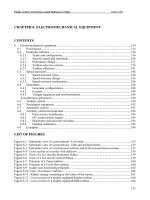
FIGURE 1:
EQUIVALENT CIRCUIT
MODEL OF A SMALL LOOP
ANTENNA
L
Rrad
Rloss
Figure 1 shows an equivalent circuit of a loop antenna
consisting of two resistors and an inductor. The resistor
Rrad, or radiation resistance, models the radio frequency energy actually radiated by the antenna. Rrad
models the desired function of the antenna, which is to
radiate RF power. Assuming a uniform current I flowing
through the loop, the power consumed by Rrad (i.e.,
the radiated power) is shown in Equation 1.
EQUATION 1:
2
Pradiated = I ⋅ Rrad
The second resistor in the model, Rloss, models
losses. Rloss models an undesired, but inevitable function of the antenna: to waste valuable RF energy by
converting it to heat. If Rloss is larger than Rrad, the
antenna is inefficient, since most of the available RF
power will end up as heat. With current I flowing
through the loop, the lost power (converted to heat) is
given by Equation 2.
2002 Microchip Technology Inc.
2
Ploss = I ⋅ Rloss
Note that we assume that the current I is uniform
around the small loop. This assumption is only valid if
the loop circumference is smaller than one fifth of a
wavelength.
For completeness, note that the total power delivered
to the antenna is given by the sum of the radiated
power and losses. From Equation 1 and Equation 2, we
get Equation 3:
EQUATION 3:
Ptotal = Pradiated + Ploss = I2⋅ (Rrad+Rloss)
In practice, the loop antenna designer has little control
over Rrad and Rloss. Rrad is determined by the area of
the loop antenna and Rloss is a function of conductor
size and conductivity, as shown in Equation 4 and 5.
CALCULATING THE LOOP
RADIATION RESISTANCE AND LOSS
RESISTANCE
The radiation resistance Rrad of a small loop antenna
is given by reference [2] as:
EQUATION 4:
A2
Rrad = 31171
λ4
where A is the area of the loop in square meter and λ is
the wavelength in meters at the radiation frequency. It
should be clear from Equation 4 that the radiation resistance of small loops will be in the milliohm range. The
wavelength λ can be calculated as λ = 3⋅108/f where f
is the radiating frequency in Hertz.
The loss resistance Rloss of a loop antenna is given by
reference [2] as:
EQUATION 5:
l
πfµ
Rloss = ------- ⋅ --------2w
σ
DS00831B-page 1
AN831
where l is the perimeter (circumference) of the loop in
meters, w is the width of the PCB track in meters, f is
the radiating frequency in Hertz, µ = 4π⋅10-7 and σ is
the conductivity of the PCB track in Siemens per meter.
Copper conductivity is typically 5.7⋅107 S/m.
Equation 5 is essentially the result of the ‘skin effect’ [2]
at high frequency for nonmagnetic materials. In this
case, the perimeter of the conductor, normally 2πr for a
round wire, has been approximated by 2w. In other
words, its perimeter is 2 times the PCB trace width.
CALCULATING THE INDUCTANCE OF
THE LOOP
The third component in the model of Figure 1 is the
loop inductance L. Inductance is primarily a magnetic
effect, and general inductance formulas for even simple shapes are hard to derive. Several formulas for calculating the inductance of rectangular loops have been
proposed. Most of these formulas are lengthy [2,3,4].
Grover’s book [3], which is the primary reference work
on inductance, provides one remarkably simple, but
accurate formula for calculating the inductance of polygons. This formula includes, but is not limited to rectangular loops. The inductance formula given by Grover
[3] is:
Using Equation 4, we calculate radiation resistance at
434 MHz as Rrad = 0.0227 Ω.
Using Equation 5, we calculate loss resistance at
434 MHz as Rloss = 0.252 Ω (σ of copper 5.7*107).
Using Equation 6, we calculate loop inductance as
L = 65.67 nH.
Summing the loss resistance and radiation resistance,
total loop resistance is calculated to be r = 0.275 Ω.
Matching the Loop to a 1 kΩ Source
Impedance
A typical CMOS radio frequency integrated circuit, such
as the rfPIC12C509AG, has a source impedance
around 1 kΩ. In the example above, the impedance of
a typical loop has an inductance of 65.67 nH in series
with a small resistance of 0.275 Ω. To match such an
antenna to the source, this low resistance and high
inductive reactance must be transformed to 1 kΩ.
The impedance transformation required is achieved by
adding a second, smaller loop to our antenna, as well
as a capacitor C, as shown in Figure 3.
FIGURE 3:
ADDING A SMALL SECOND
LOOP AND CAPACITOR
C inserted here
EQUATION 6:
µ
8⋅A
L = ------ ⋅ l ⋅ 1n -----------
l ⋅ w
2π
where µ = 4π⋅10-7, A is the area of the loop in square
meters, l is the perimeter (circumference) of the loop in
meters, and w is the width of the copper trace in meters.
CALCULATION OF LOOP
PARAMETERS
EXAMPLE 1:
The magnetic coupling between the large loop and
small loop results in transformer action. The large loop,
or loop antenna, makes up the secondary winding of
our transformer. The small loop becomes the primary
winding of our transformer.
The total loop resistance, that is the sum of radiation
resistance and loss resistance, is calculated to be
0.249 Ω.
Figure 4 is a revised circuit model of the loop antenna,
showing the transformer action. The loop antenna's
total resistance r, consisting of Rrad + Rloss, forms the
resistive load in the secondary circuit. Also note a
capacitance C in the secondary circuit. Capacitor C is
primarily used to cancel the loop inductance LS. The
capacitance may be approximated as follows:
FIGURE 2:
EQUATION 7:
Suppose a designer is constrained by PCB loop
antenna dimensions of 34 mm x 12 mm. The copper
track width is 1 mm.
DS00831B-page 2
PCB COPPER LOOP
34 mm x 12 mm x 1 mm
1
C ≈ ------------2
Lsω
2002 Microchip Technology Inc.
AN831
FIGURE 4:
REVISED LOOP ANTENNA
EQUIVALENT CIRCUIT
Equation 10 shows how the transformer action translates the low loop resistance r of the small loop
antenna:
• The resistance is inverted.
• The inverted resistance is then multiplied by the
square of the mutual reactance, (ωM)2.
C
Equation 10 can be rewritten as:
Lp
Ls
r
EQUATION 11:
r ⋅ Rp
M ≈ -----------------ω
MAGNETIC COUPLING
Magnetic coupling between the primary and secondary
windings is at the root of the impedance transformation.
We now write the basic voltage and current equations
for the above magnetically coupled circuit:
Equation 11 shows the mutual inductance needed to
transform a loop impedance of r ohm into a needed
source impedance of Rp ohm.
Next, we find a way to calculate mutual inductance M
as a function of loop dimensions.
Obtaining a Given Mutual Inductance
EQUATION 8:
V p = jωL p I p + jωMI s
1
0 = jωMI p + jωL s Is – j -------- I s + rI s
ωC
A formula for the calculation of mutual inductance
between two off-center, coplanar rectangles is daunting. However, two reasonable assumptions simplify the
calculation significantly. The assumptions are:
1.
where Vp is the primary voltage, Ip the primary current,
Is the secondary current and ω the angular frequency,
equal to 2⋅π⋅f. M is the mutual inductance, which is a
function of the degree of magnetic coupling between
the two loops.
By using Equation 8, the real part (resistive portion) of
the load impedance as seen from the primary side of
the transformer can be derived:
Assume that only one side of the loop antenna
couples magnetically to the small loop. The
other three sides are much further away, so we
may neglect their effect. This assumption simplifies the mutual inductance calculation problem
to that of mutual inductance between a straight
wire (or PCB track), and the small loop, as
drawn in Figure 5.
FIGURE 5:
USING ONLY ONE SIDE OF
THE LARGE LOOP
w
EQUATION 9:
lb
2
r
Re ( Zp ) = ( ωM ) ⋅ --------------------------------------------------2
1 2
r + ωL s – --------
ωC
Near resonance the term
1 2
ωL – ------ s ωC
la
2.
It is assumed that the straight wire of Figure 5
stretches to infinity, as drawn in Figure 6. This is
reasonable because the part of the wire close to
the loop is the dominating contributor of magnetic flux in the small loop.
becomes small, so that it is possible to estimate the
resistive load as seen from the primary side by:
EQUATION 10:
2 1
R p ≈ ( ωM ) ⋅ --r
2002 Microchip Technology Inc.
DS00831B-page 3
AN831
FIGURE 6:
INFINITE WIRE AND SMALL
LOOP
w
lb
la
The two assumptions greatly simplify the calculation of
mutual inductance. The mutual inductance of the loopand-wire of Figure 6 is a popular college physics [5]
problem with a compact result:
EQUATION 12:
EXAMPLE 2:
Continuing our loop antenna of Example 1:
1.
2.
3.
From Example 1, we calculated the loop series
resistance as r = 0.275 Ω
The needed antenna impedance is 1 kΩ.
From Equation 14, we calculate la = 13.8 mm,
using f = 434 MHz.
CONCLUSION
A simple method to match a small loop antenna has
been found. By adding a small primary loop and by
controlling the mutual inductance of the resulting transformer, the low loop resistance is transformed to the
value desired for maximum power transfer.
4⋅l
µ
b
M = ------ ⋅ l a ⋅ ln 1 + ------------
2π
w
Where M is mutual inductance in Henry, la is the rectangle dimension parallel to the wire, lb is the rectangle
dimension perpendicular to the wire, and w is the width
of the PCB track. All dimensions are in meter, and
µ = 4π⋅10-7.
By setting the rectangle dimension lb to 2 times the
PCB track width, in other words, setting lb = 2w, we find
that Equation 12 simplifies to:
EQUATION 13:
µ
8w
M = ------ ⋅ l ⋅ ln 1 + -------
2π a
w
µ
M = ------ ⋅ l a ⋅ ln ( 1 + 8 )
2π
By combining Equations 11 and 13, an expression for
loop dimension la is found as follows:
EQUATION 14:
r ⋅ Rp
l a = --------------------------µ ⋅ f ⋅ ln ( 9 )
Equation 14 is the final result and provides a simple
method to match to a small loop antenna, which is summarized below.
1.
2.
3.
Calculate the loop series resistance r using
Equations 4 and 5.
Determine the required impedance Rp.
Calculate la of a small matching loop using
Equation 14.
DS00831B-page 4
2002 Microchip Technology Inc.
AN831
REFERENCES
[1] K. Fujimoto and J.R. James, Mobile Antenna
Systems, Second Edition Artech House 2001
ISBN 1-58053-007-9
[2] K. Fujimoto, A. Henderson, K. Hirasawa and
J.R. James, Small Antennas, Research Studies,
Press LTD 1987 ISBN 0 86380 048 3 (Research
Studies Press) ISBN 0 471 91413 4 (John Wiley
& Sons Inc)
[3] Frederick W. Grover, Inductance Calculations
Working Formulas and Tables, Dover Publications Inc. 1946
[4] V.G. Welsby, The Theory and Design of Inductance Coils, 2nd Edition John Wiley & Sons Inc.
1960
[5] Matthew N.O. Sadiku, Elements of Electromagnetics, Third Edition Oxford University Press
2001 ISBN 0-19-513477-X
[6] Thomas H. Lee, The Design of CMOS RadioFrequency Integrated Circuits, Cambridge University Press 1998 ISBN 0-521-63061-4 (hb)
ISBN 0-521-63922-0 (pb)
[7] Chris Bowick, RF Circuit Design, H.W. Sams
1982 ISBN 0-7506-9946-9
2002 Microchip Technology Inc.
DS00831B-page 5
AN831
APPENDIX A:
COMPLEX IMPEDANCE
Equation 9 shows only the real part of the primary side impedance. The entire complex impedance as seen on the primary side is:
EQUATION 15:
2 2
r
Z p = ω M ⋅ --------------------------------------------------2
1 2
r + ωL s – --------
ωC
+
j
2 2
1
ω M ⋅ ωL s – --------
ωC
ωL p – --------------------------------------------------2
1 2
r + ωL s – --------
ωC
M is mutual inductance, r is loop resistance, Ls is secondary (large) loop inductance and Lp is primary loop inductance.
Lp and Ls are both calculated using Equation 6.
An exact value for the capacitance C at resonance can be found by setting the imaginary part of Equation 15 to zero.
DS00831B-page 6
2002 Microchip Technology Inc.
Note the following details of the code protection feature on PICmicro® MCUs.
•
•
•
•
•
•
The PICmicro family meets the specifications contained in the Microchip Data Sheet.
Microchip believes that its family of PICmicro microcontrollers is one of the most secure products of its kind on the market today,
when used in the intended manner and under normal conditions.
There are dishonest and possibly illegal methods used to breach the code protection feature. All of these methods, to our knowledge, require using the PICmicro microcontroller in a manner outside the operating specifications contained in the data sheet.
The person doing so may be engaged in theft of intellectual property.
Microchip is willing to work with the customer who is concerned about the integrity of their code.
Neither Microchip nor any other semiconductor manufacturer can guarantee the security of their code. Code protection does not
mean that we are guaranteeing the product as “unbreakable”.
Code protection is constantly evolving. We at Microchip are committed to continuously improving the code protection features of
our product.
If you have any further questions about this matter, please contact the local sales office nearest to you.
Information contained in this publication regarding device
applications and the like is intended through suggestion only
and may be superseded by updates. It is your responsibility to
ensure that your application meets with your specifications.
No representation or warranty is given and no liability is
assumed by Microchip Technology Incorporated with respect
to the accuracy or use of such information, or infringement of
patents or other intellectual property rights arising from such
use or otherwise. Use of Microchip’s products as critical components in life support systems is not authorized except with
express written approval by Microchip. No licenses are conveyed, implicitly or otherwise, under any intellectual property
rights.
Trademarks
The Microchip name and logo, the Microchip logo, FilterLab,
KEELOQ, microID, MPLAB, PIC, PICmicro, PICMASTER,
PICSTART, PRO MATE, SEEVAL and The Embedded Control
Solutions Company are registered trademarks of Microchip Technology Incorporated in the U.S.A. and other countries.
dsPIC, ECONOMONITOR, FanSense, FlexROM, fuzzyLAB,
In-Circuit Serial Programming, ICSP, ICEPIC, microPort,
Migratable Memory, MPASM, MPLIB, MPLINK, MPSIM,
MXDEV, PICC, PICDEM, PICDEM.net, rfPIC, Select Mode
and Total Endurance are trademarks of Microchip Technology
Incorporated in the U.S.A.
Serialized Quick Turn Programming (SQTP) is a service mark
of Microchip Technology Incorporated in the U.S.A.
All other trademarks mentioned herein are property of their
respective companies.
© 2002, Microchip Technology Incorporated, Printed in the
U.S.A., All Rights Reserved.
Printed on recycled paper.
Microchip received QS-9000 quality system
certification for its worldwide headquarters,
design and wafer fabrication facilities in
Chandler and Tempe, Arizona in July 1999. The
Company’s quality system processes and
procedures are QS-9000 compliant for its
PICmicro® 8-bit MCUs, KEELOQ® code hopping
devices, Serial EEPROMs and microperipheral
products. In addition, Microchip’s quality
system for the design and manufacture of
development systems is ISO 9001 certified.
2002 Microchip Technology Inc.
DS00831B - page 7
WORLDWIDE SALES AND SERVICE
AMERICAS
ASIA/PACIFIC
Japan
Corporate Office
Australia
2355 West Chandler Blvd.
Chandler, AZ 85224-6199
Tel: 480-792-7200 Fax: 480-792-7277
Technical Support: 480-792-7627
Web Address:
Microchip Technology Australia Pty Ltd
Suite 22, 41 Rawson Street
Epping 2121, NSW
Australia
Tel: 61-2-9868-6733 Fax: 61-2-9868-6755
Microchip Technology Japan K.K.
Benex S-1 6F
3-18-20, Shinyokohama
Kohoku-Ku, Yokohama-shi
Kanagawa, 222-0033, Japan
Tel: 81-45-471- 6166 Fax: 81-45-471-6122
Rocky Mountain
China - Beijing
2355 West Chandler Blvd.
Chandler, AZ 85224-6199
Tel: 480-792-7966 Fax: 480-792-7456
Microchip Technology Consulting (Shanghai)
Co., Ltd., Beijing Liaison Office
Unit 915
Bei Hai Wan Tai Bldg.
No. 6 Chaoyangmen Beidajie
Beijing, 100027, No. China
Tel: 86-10-85282100 Fax: 86-10-85282104
Atlanta
500 Sugar Mill Road, Suite 200B
Atlanta, GA 30350
Tel: 770-640-0034 Fax: 770-640-0307
Boston
2 Lan Drive, Suite 120
Westford, MA 01886
Tel: 978-692-3848 Fax: 978-692-3821
Chicago
333 Pierce Road, Suite 180
Itasca, IL 60143
Tel: 630-285-0071 Fax: 630-285-0075
Dallas
4570 Westgrove Drive, Suite 160
Addison, TX 75001
Tel: 972-818-7423 Fax: 972-818-2924
Detroit
Tri-Atria Office Building
32255 Northwestern Highway, Suite 190
Farmington Hills, MI 48334
Tel: 248-538-2250 Fax: 248-538-2260
Kokomo
2767 S. Albright Road
Kokomo, Indiana 46902
Tel: 765-864-8360 Fax: 765-864-8387
Los Angeles
18201 Von Karman, Suite 1090
Irvine, CA 92612
Tel: 949-263-1888 Fax: 949-263-1338
China - Chengdu
Microchip Technology Consulting (Shanghai)
Co., Ltd., Chengdu Liaison Office
Rm. 2401, 24th Floor,
Ming Xing Financial Tower
No. 88 TIDU Street
Chengdu 610016, China
Tel: 86-28-6766200 Fax: 86-28-6766599
China - Fuzhou
Microchip Technology Consulting (Shanghai)
Co., Ltd., Fuzhou Liaison Office
Unit 28F, World Trade Plaza
No. 71 Wusi Road
Fuzhou 350001, China
Tel: 86-591-7503506 Fax: 86-591-7503521
China - Shanghai
Microchip Technology Consulting (Shanghai)
Co., Ltd.
Room 701, Bldg. B
Far East International Plaza
No. 317 Xian Xia Road
Shanghai, 200051
Tel: 86-21-6275-5700 Fax: 86-21-6275-5060
China - Shenzhen
150 Motor Parkway, Suite 202
Hauppauge, NY 11788
Tel: 631-273-5305 Fax: 631-273-5335
Microchip Technology Consulting (Shanghai)
Co., Ltd., Shenzhen Liaison Office
Rm. 1315, 13/F, Shenzhen Kerry Centre,
Renminnan Lu
Shenzhen 518001, China
Tel: 86-755-2350361 Fax: 86-755-2366086
San Jose
Hong Kong
Microchip Technology Inc.
2107 North First Street, Suite 590
San Jose, CA 95131
Tel: 408-436-7950 Fax: 408-436-7955
Microchip Technology Hongkong Ltd.
Unit 901-6, Tower 2, Metroplaza
223 Hing Fong Road
Kwai Fong, N.T., Hong Kong
Tel: 852-2401-1200 Fax: 852-2401-3431
New York
Toronto
6285 Northam Drive, Suite 108
Mississauga, Ontario L4V 1X5, Canada
Tel: 905-673-0699 Fax: 905-673-6509
India
Microchip Technology Inc.
India Liaison Office
Divyasree Chambers
1 Floor, Wing A (A3/A4)
No. 11, O’Shaugnessey Road
Bangalore, 560 025, India
Tel: 91-80-2290061 Fax: 91-80-2290062
Korea
Microchip Technology Korea
168-1, Youngbo Bldg. 3 Floor
Samsung-Dong, Kangnam-Ku
Seoul, Korea 135-882
Tel: 82-2-554-7200 Fax: 82-2-558-5934
Singapore
Microchip Technology Singapore Pte Ltd.
200 Middle Road
#07-02 Prime Centre
Singapore, 188980
Tel: 65-6334-8870 Fax: 65-6334-8850
Taiwan
Microchip Technology Taiwan
11F-3, No. 207
Tung Hua North Road
Taipei, 105, Taiwan
Tel: 886-2-2717-7175 Fax: 886-2-2545-0139
EUROPE
Denmark
Microchip Technology Nordic ApS
Regus Business Centre
Lautrup hoj 1-3
Ballerup DK-2750 Denmark
Tel: 45 4420 9895 Fax: 45 4420 9910
France
Microchip Technology SARL
Parc d’Activite du Moulin de Massy
43 Rue du Saule Trapu
Batiment A - ler Etage
91300 Massy, France
Tel: 33-1-69-53-63-20 Fax: 33-1-69-30-90-79
Germany
Microchip Technology GmbH
Gustav-Heinemann Ring 125
D-81739 Munich, Germany
Tel: 49-89-627-144 0 Fax: 49-89-627-144-44
Italy
Microchip Technology SRL
Centro Direzionale Colleoni
Palazzo Taurus 1 V. Le Colleoni 1
20041 Agrate Brianza
Milan, Italy
Tel: 39-039-65791-1 Fax: 39-039-6899883
United Kingdom
Arizona Microchip Technology Ltd.
505 Eskdale Road
Winnersh Triangle
Wokingham
Berkshire, England RG41 5TU
Tel: 44 118 921 5869 Fax: 44-118 921-5820
03/01/02
DS00831B-page 8
2002 Microchip Technology Inc.