AN1004 using the c18 compiler to interface microwire serial EEPROMs to PIC18 devices
Bạn đang xem bản rút gọn của tài liệu. Xem và tải ngay bản đầy đủ của tài liệu tại đây (437.7 KB, 10 trang )
AN1004
Using the C18 Compiler to Interface Microwire Serial EEPROMs to PIC18 Devices
Author:
This application note provides assistance and source
code to ease the design process of interfacing a
Microchip PIC18F1220 PICmicro® microcontroller to a
Microchip Microwire serial EEPROM, without the use of
a hardware serial port.
Chris Parris
Microchip Technology Inc.
INTRODUCTION
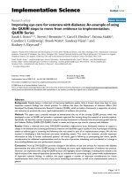
Figure 1 depicts the hardware schematic for the interface between Microchip’s Microwire devices and the
Microchip PIC18F1220 microcontroller. The schematic
shows the necessary connections to interface the
microcontroller and the serial EEPROM (the firmware
was written assuming these connections).
There are many different microcontrollers on the
market today that are being used in embedded control
applications. Many of these embedded control systems
need nonvolatile memory. Because of their small footprint, byte level flexibility, low I/O pin requirement, low
power consumption and low cost, serial EEPROMs are
a popular choice for nonvolatile storage.
Microchip Technology has addressed these needs by
offering a full line of serial EEPROMs covering industry
standard serial communication protocols for two-wire
(I2C™), three-wire (Microwire), and SPI™ communication. Serial EEPROM devices are available in a variety
of densities, operational voltage ranges, and packaging
options.
CIRCUIT FOR PIC18F1220 AND 93 SERIES (MICROWIRE) DEVICE
PDIP (300 MIL)
RA0
RA1
RA4
MCLR/VPP
VSS
RA2
RA3
RB0
RB1
1
2
3
4
5
6
7
8
9
PIC18F1220
FIGURE 1:
RB3
RB2
OSC1
OSC2
VDD
RB7/PGD
RB6/PGC
RB5
RB4
18
17
16
15
14
13
12
11
10
CS(1)
1
CLK
2
DI
3
DO
4
10K
Note
93XXXXX
Vcc
8
Vcc
7
PE(2)
6
ORG(3)
5
Vss
10K
1:
CS should always have a pull-down resistor to protect against data corruption during power-up or power-down of the microcontroller.
2:
PE pin available only on 93XX76X and 93XX86X devices. Pull-up resistor suggested ~10 kOhm.
3:
ORG pin available only on 93XXXXC devices.
© 2005 Microchip Technology Inc.
DS01004A-page 1
AN1004
FIRMWARE DESCRIPTION
The purpose of the program is to show individual
features of the Microwire protocol and give code
samples of the Start bit, opcodes and addressing
schemes, so that the basic building blocks of a program
can be shown. The firmware performs five basic
operations:
•
•
•
•
•
Erase/Write Enable command
Write command for one word of data
Ready/Busy polling
Read command for one word of data
Erase/Write Disable command
Functions are provided for both 8-bit and 16-bit organizations. However, only the 8-bit functions are exhibited
in this application note.
The 8-bit functions were tested using the 93LC66A
serial EEPROM, featuring 512 x 8 (4 Kbit) of memory
and 8-bit organization. The 16-bit functions were tested
using the 93LC66B serial EEPROM, which features
256 x 16 (4 Kbit) of memory and 16-bit organization.
The provided screenshots are of the 8-bit functions
only.
A 10 MHz crystal oscillator is used to clock the
PIC18F1220. If a faster clock is used, the code may
need to be modified to ensure all timing specs are met.
The waveforms provided are shown from CS active to
CS disable so an entire instruction can be seen. To
ease the interpretation of the serial data, the data sheet
waveforms are provided below the oscilloscope screen
shots. All values represented in this application note
are decimal values unless otherwise noted.
Device Setup
Although this application note focuses on the 93LC66A
device, the firmware supports all 93XXXX devices. This
is done by setting the NUMBITS constant at the
beginning of the source code.
The NUMBITS constant is used in the output subroutines to determine how many bits are required to be
output. More specifically, it is used by the EWEN and
EWDS commands to calculate the number of dummy
bits required. It is also used by the Read and Write subroutines to skip over the unused bits in the address
word. This constant must equal the required number of
clock cycles for an EWEN command (12 for the
93XX66A).
Note:
On devices of the same density, the
required number of clock cycles differs
between 8-bit and 16-bit organizations.
Therefore, if the organization is changed,
NUMBITS must be updated appropriately.
DS01004A-page 2
© 2005 Microchip Technology Inc.
AN1004
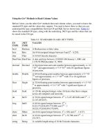
WRITE ENABLE
Figure 2 shows an example of the Erase/Write Enable
(EWEN) command. Chip Select is brought high
(active), and the Start bit and four-bit opcode (‘0011’)
are sent out first, with the required number of dummy
bits (7 for the 93XX66A) following.
FIGURE 2:
The EWEN command must be given before a write is
attempted. The device will be enabled for writes until an
Erase/Write Disable command is given or the device is
powered down.
ERASE/WRITE ENABLE (EWEN)
TCSL
CS
CLK
DI
1
© 2005 Microchip Technology Inc.
0
0
1
1
x
•••
x
DS01004A-page 3
AN1004
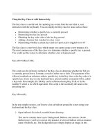
WRITE COMMAND (START BIT,
OPCODE, ADDRESS AND DATA)
Once the internal write cycle has begun, the Ready/
Busy signal can be polled on the DO pin to check when
the write finishes. A 6 ms delay needs to be added if the
Ready/Busy status is not being polled. This code uses
Ready/Busy polling.
Figure 3 shows an example of the Write command. The
device is selected and the Start bit, opcode and the
word address are sent out. Next, the data is clocked out
to the device. When the Chip Select is toggled, the
internal write cycle is initiated.
FIGURE 3:
WRITE COMMAND, ADDRESS AND DATA
TCSL
CS
CLK
DI
1
0
1
An
•••
A0
Dx
•••
D0
TSV
DO
High-Z
Busy
TCZ
Ready
High-Z
TWC
DS01004A-page 4
© 2005 Microchip Technology Inc.
AN1004
READY/BUSY POLLING
After a valid Write command is given, the DO line of the
93XXXX can be monitored to check if the internal write
cycle has been successfully initiated and, if so, to
determine when the write cycle is complete. The oscilloscope plot below shows that the device is selected
and the DO line is low for approximately 3.0 ms before
the device brings the DO line high, indicating that the
write cycle is complete.
This illustrates that the write cycle typically is much
shorter than the specified maximum. Therefore, it can
be highly beneficial to take advantage of the Ready/
Busy polling feature, so as to increase efficiency when
writing multiple words of data to the device.
Note that the 93AAXX and 93LCXX devices have a
maximum program cycle time (TWC) of 6 ms, but in this
example, the write cycle only lasted 3.0 ms.
FIGURE 4:
READY/BUSY POLLING
© 2005 Microchip Technology Inc.
DS01004A-page 5
AN1004
READ COMMAND (START BIT,
OPCODE, ADDRESS AND DATA)
Figure 5 shows an example of the Read command.
The device is selected and the Start bit, opcode and the
word address are sent out. At this point, the device gets
ready to transmit data. The microcontroller must
generate the clock signals and read DO on each falling
clock edge. In this example, the data being read is
0x55.
FIGURE 5:
READ COMMAND
CS
CLK
DI
DO
DS01004A-page 6
1
High-Z
1
0
An
•••
A0
0
Dx
•••
D0
Dx
•••
D0
Dx
•••
D0
© 2005 Microchip Technology Inc.
AN1004
ERASE/WRITE DISABLE COMMAND
The EWDS command should always be sent to the
device after completing a write or prior to powering
down the device/system.
Once the internal write cycle is complete, the Write Disable (EWDS) command should be given (see
Figure 6). This command consists of a Start bit and the
four-bit opcode (‘0000’), followed by the appropriate
number of dummy bits (7 for the 93XX66A).
FIGURE 6:
ERASE/WRITE DISABLE COMMAND
TCSL
CS
CLK
DI
1
0
© 2005 Microchip Technology Inc.
0
0
0
x
•••
x
DS01004A-page 7
AN1004
CONCLUSION
These are some of the basic features of Microwire
communications on one of Microchip’s PIC18 devices
without the use of a hardware serial port. The code is
highly portable and can be used on many PICmicro®
microcontrollers, with very minor modifications. Using
the code provided, designers can begin to build their
own Microwire libraries to be as simple or as complex
as needed.
DS01004A-page 8
© 2005 Microchip Technology Inc.
Note the following details of the code protection feature on Microchip devices:
•
Microchip products meet the specification contained in their particular Microchip Data Sheet.
•
Microchip believes that its family of products is one of the most secure families of its kind on the market today, when used in the
intended manner and under normal conditions.
•
There are dishonest and possibly illegal methods used to breach the code protection feature. All of these methods, to our
knowledge, require using the Microchip products in a manner outside the operating specifications contained in Microchip’s Data
Sheets. Most likely, the person doing so is engaged in theft of intellectual property.
•
Microchip is willing to work with the customer who is concerned about the integrity of their code.
•
Neither Microchip nor any other semiconductor manufacturer can guarantee the security of their code. Code protection does not
mean that we are guaranteeing the product as “unbreakable.”
Code protection is constantly evolving. We at Microchip are committed to continuously improving the code protection features of our
products. Attempts to break Microchip’s code protection feature may be a violation of the Digital Millennium Copyright Act. If such acts
allow unauthorized access to your software or other copyrighted work, you may have a right to sue for relief under that Act.
Information contained in this publication regarding device
applications and the like is provided only for your convenience
and may be superseded by updates. It is your responsibility to
ensure that your application meets with your specifications.
MICROCHIP MAKES NO REPRESENTATIONS OR WARRANTIES OF ANY KIND WHETHER EXPRESS OR IMPLIED,
WRITTEN OR ORAL, STATUTORY OR OTHERWISE,
RELATED TO THE INFORMATION, INCLUDING BUT NOT
LIMITED TO ITS CONDITION, QUALITY, PERFORMANCE,
MERCHANTABILITY OR FITNESS FOR PURPOSE.
Microchip disclaims all liability arising from this information and
its use. Use of Microchip’s products as critical components in
life support systems is not authorized except with express
written approval by Microchip. No licenses are conveyed,
implicitly or otherwise, under any Microchip intellectual property
rights.
Trademarks
The Microchip name and logo, the Microchip logo, Accuron,
dsPIC, KEELOQ, microID, MPLAB, PIC, PICmicro, PICSTART,
PRO MATE, PowerSmart, rfPIC, and SmartShunt are
registered trademarks of Microchip Technology Incorporated
in the U.S.A. and other countries.
AmpLab, FilterLab, Migratable Memory, MXDEV, MXLAB,
PICMASTER, SEEVAL, SmartSensor and The Embedded
Control Solutions Company are registered trademarks of
Microchip Technology Incorporated in the U.S.A.
Analog-for-the-Digital Age, Application Maestro, dsPICDEM,
dsPICDEM.net, dsPICworks, ECAN, ECONOMONITOR,
FanSense, FlexROM, fuzzyLAB, In-Circuit Serial
Programming, ICSP, ICEPIC, Linear Active Thermistor,
MPASM, MPLIB, MPLINK, MPSIM, PICkit, PICDEM,
PICDEM.net, PICLAB, PICtail, PowerCal, PowerInfo,
PowerMate, PowerTool, rfLAB, rfPICDEM, Select Mode,
Smart Serial, SmartTel, Total Endurance and WiperLock are
trademarks of Microchip Technology Incorporated in the
U.S.A. and other countries.
SQTP is a service mark of Microchip Technology Incorporated
in the U.S.A.
All other trademarks mentioned herein are property of their
respective companies.
© 2005, Microchip Technology Incorporated, Printed in the
U.S.A., All Rights Reserved.
Printed on recycled paper.
Microchip received ISO/TS-16949:2002 quality system certification for
its worldwide headquarters, design and wafer fabrication facilities in
Chandler and Tempe, Arizona and Mountain View, California in
October 2003. The Company’s quality system processes and
procedures are for its PICmicro® 8-bit MCUs, KEELOQ® code hopping
devices, Serial EEPROMs, microperipherals, nonvolatile memory and
analog products. In addition, Microchip’s quality system for the design
and manufacture of development systems is ISO 9001:2000 certified.
© 2005 Microchip Technology Inc.
DS01004A-page 9
WORLDWIDE SALES AND SERVICE
AMERICAS
ASIA/PACIFIC
ASIA/PACIFIC
EUROPE
Corporate Office
2355 West Chandler Blvd.
Chandler, AZ 85224-6199
Tel: 480-792-7200
Fax: 480-792-7277
Technical Support:
Web Address:
www.microchip.com
Australia - Sydney
Tel: 61-2-9868-6733
Fax: 61-2-9868-6755
India - Bangalore
Tel: 91-80-2229-0061
Fax: 91-80-2229-0062
China - Beijing
Tel: 86-10-8528-2100
Fax: 86-10-8528-2104
India - New Delhi
Tel: 91-11-5160-8631
Fax: 91-11-5160-8632
Austria - Weis
Tel: 43-7242-2244-399
Fax: 43-7242-2244-393
Denmark - Copenhagen
Tel: 45-4450-2828
Fax: 45-4485-2829
China - Chengdu
Tel: 86-28-8676-6200
Fax: 86-28-8676-6599
India - Pune
Tel: 91-20-2566-1512
Fax: 91-20-2566-1513
France - Paris
Tel: 33-1-69-53-63-20
Fax: 33-1-69-30-90-79
China - Fuzhou
Tel: 86-591-8750-3506
Fax: 86-591-8750-3521
Japan - Yokohama
Tel: 81-45-471- 6166
Fax: 81-45-471-6122
Germany - Munich
Tel: 49-89-627-144-0
Fax: 49-89-627-144-44
China - Hong Kong SAR
Tel: 852-2401-1200
Fax: 852-2401-3431
Korea - Gumi
Tel: 82-54-473-4301
Fax: 82-54-473-4302
China - Qingdao
Tel: 86-532-8502-7355
Fax: 86-532-8502-7205
Korea - Seoul
Tel: 82-2-554-7200
Fax: 82-2-558-5932 or
82-2-558-5934
Atlanta
Alpharetta, GA
Tel: 770-640-0034
Fax: 770-640-0307
Boston
Westborough, MA
Tel: 774-760-0087
Fax: 774-760-0088
Chicago
Itasca, IL
Tel: 630-285-0071
Fax: 630-285-0075
Dallas
Addison, TX
Tel: 972-818-7423
Fax: 972-818-2924
Detroit
Farmington Hills, MI
Tel: 248-538-2250
Fax: 248-538-2260
Kokomo
Kokomo, IN
Tel: 765-864-8360
Fax: 765-864-8387
Los Angeles
Mission Viejo, CA
Tel: 949-462-9523
Fax: 949-462-9608
San Jose
Mountain View, CA
Tel: 650-215-1444
Fax: 650-961-0286
Toronto
Mississauga, Ontario,
Canada
Tel: 905-673-0699
Fax: 905-673-6509
China - Shanghai
Tel: 86-21-5407-5533
Fax: 86-21-5407-5066
China - Shenyang
Tel: 86-24-2334-2829
Fax: 86-24-2334-2393
China - Shenzhen
Tel: 86-755-8203-2660
Fax: 86-755-8203-1760
China - Shunde
Tel: 86-757-2839-5507
Fax: 86-757-2839-5571
China - Wuhan
Tel: 86-27-5980-5300
Fax: 86-27-5980-5118
China - Xian
Tel: 86-29-8833-7250
Fax: 86-29-8833-7256
Malaysia - Penang
Tel: 604-646-8870
Fax: 604-646-5086
Philippines - Manila
Tel: 632-634-9065
Fax: 632-634-9069
Italy - Milan
Tel: 39-0331-742611
Fax: 39-0331-466781
Netherlands - Drunen
Tel: 31-416-690399
Fax: 31-416-690340
Spain - Madrid
Tel: 34-91-352-30-52
Fax: 34-91-352-11-47
UK - Wokingham
Tel: 44-118-921-5869
Fax: 44-118-921-5820
Singapore
Tel: 65-6334-8870
Fax: 65-6334-8850
Taiwan - Hsin Chu
Tel: 886-3-572-9526
Fax: 886-3-572-6459
Taiwan - Kaohsiung
Tel: 886-7-536-4818
Fax: 886-7-536-4803
Taiwan - Taipei
Tel: 886-2-2500-6610
Fax: 886-2-2508-0102
Thailand - Bangkok
Tel: 66-2-694-1351
Fax: 66-2-694-1350
08/24/05
DS01004A-page 10
© 2005 Microchip Technology Inc.


![ipad for kids [electronic resource] using the ipad to play and learn](https://media.store123doc.com/images/document/14/y/pi/medium_pip1401383474.jpg)