AN1045 implementing file IO functions using microchip’s memory disk drive file system library
Bạn đang xem bản rút gọn của tài liệu. Xem và tải ngay bản đầy đủ của tài liệu tại đây (350.65 KB, 44 trang )
AN1045
Implementing File I/O Functions Using Microchip’s Memory
Disk Drive File System Library
Authors:
Peter Reen and Naveen Mohanswamy
Microchip Technology Inc.
INTRODUCTION
This application note describes the usage of file I/O
functions using Microchip’s memory disk drive file
system library. Microchip’s memory disk drive file
system is:
• Based on ISO/IEC 9293 specifications
• Known as the FAT16 file system, used on earlier
DOS operating systems by Microsoft® Corporation
• Also supports the FAT32 file system
• Most popular file system with SD (Secure
Digital) card, CF (CompactFlash®) card and USB
thumb drive
Most SD cards and MMCs (MultiMedia Cards), particularly those sized below 2 gigabytes (GBs), use the
FAT16 standard. The FAT32 standard can be used to
address memory sized between 2 gigabytes and
2 terabytes. This application note provides a method to
read and/or write to these storage devices through a
microcontroller. The data of these storage devices can
be read by a PC, and the data written by a PC can be
read by a microcontroller. Most operating systems (i.e.,
Windows® XP) support the FAT16 and FAT32 file
systems.
SD CARDS AND MMCS
SD cards and MMCs are proprietary and removable
Flash technology-based media licensed by the SD
Card Association and the MM Card Association (see
“References”).
Functionally, the two card formats are similar. However,
the SD card has optional encryption security features
that are not customarily found on the MMC. The
specifications of these devices and the terms and
conditions for their use vary, and should be verified for
further application licensing information.
© 2008 Microchip Technology Inc.
INTERFACE
The PICtail™ Daughter Board for SD and MMC,
Microchip product number AC164122, provides an
interface
between
SD
or
MMC
and
a
PIC® microcontroller through the Serial Peripheral
Interface (SPI) bus. The PICtail Daughter Board is
designed to operate with a multitude of demonstration
boards, including all those having PICtail or PICtail
Plus Daughter Board interfaces.
The SPI protocol uses four basic pins for
communication: Serial Data In (SDI), Serial Data Out
(SDO), Serial Clock (SCK), and Chip Select (CS).
Additionally, all SD card sockets have two electrically
determined signals, card detect and write-protect that
allow the user to determine if the card is physically
inserted and/or write-protected.
The MMC does not have a physical write-protect
signal, but most card connectors will default to a
non-write-protected state in this case.
For more information about interfacing PIC microcontrollers to SD cards or MMCs, refer to AN1003,
“USB Mass Storage Device Using a PIC® MCU”
(DS01003) available on the Microchip web site
(www.microchip.com).
Important:
It is the user’s responsibility to obtain a
copy of, familiarize themselves fully
with, and comply with the requirements
and licensing obligations applicable to
third party tools, systems and/or
specifications including, but not limited
to, Flash-based media and FAT file
systems available from CompactFlash
Association, SD Card Association,
MultiMediaCard
Association
and
Microsoft Corporation.
Refer to the license agreement for
details.
DS01045B-page 1
AN1045
CARD FILE SYSTEM
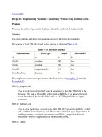
FIGURE 1:
DISK STRUCTURE
A FAT16 file system stores data in sectors. A sector
size of 512 bytes is common. Since the number of
available memory addresses is capped at FFFFh,
sectors can be grouped into clusters that share an
address to increase the size of the card.
Master Boot Record
Unused Disk Space
Boot Sector
Unused Disk Space
The first sector on a card is the Master Boot Record
(MBR). The MBR contains information about different
logical subdivisions on a card, known as partitions.
Each partition can be formatted with a unique file
system. Typically, an SD card or MMC has only one
active partition, which comprises the following parts:
Collectively, the first three sections are the system
area. The remaining space is the data region.
• Data Region – Stores file data or subdirectory
directory tables. The data stored in this region
remains intact even if it is deleted or until it is
overwritten.
The FAT16 system uses 16-bit FAT entries, allowing
approximately 65,536 (216) clusters to be represented;
the FAT32 system uses 32-bit FAT entries (effectively
only 28 bits) allowing approximately 268,435,456 (228)
clusters to be addressed.
A signed byte in the boot sector defines the number of
sectors per cluster for a disk. This byte has a range of
-128 to 127. The only usable values in the FAT file
system are positive, power-of-two values (1, 2, 4, 8, 16,
32 and 64). This means with the standard 512-byte
sector, the FAT16 file system can support a maximum
of 2 GB disk space.
Partition 1
Space
• Boot Sector – This is the first sector of the
partition and contains basic information about the
file system type.
• FAT Regions – This region is the map of the card,
which indicates how the clusters are allocated in
the data region. Generally, there are two copies of
the FAT in this region to provide redundancy in
case of data corruption.
• Root Directory Region – In the FAT16 file system,
this region follows the FAT region. In the FAT32
file system, the root is an ordinary cluster chain
and can be located anywhere on the volume. The
root directory is composed of a directory table that
contains entries for subdirectories and files. Other
directories and files have entries in the directory
tables of the directories in the root.
FAT 1
FAT n
Root Directory
Data Space
Legend:
n = number of FATs.
Master Boot Record
The MBR contains information that is used to boot the
card and information about the partitions on the card.
The information in the MBR is programmed at the time
of manufacture and any attempt to write to the MBR
could render the disk unusable.
Table 1 provides the contents of the MBR.
TABLE 1:
Offset
CONTENTS OF THE MBR
Description
Size
000h
Boot Code (machine code and
data).
446 bytes
1BEh
Partition Entry 1.
16 bytes
1CEh
Partition Entry 2.
16 bytes
1DEh
Partition Entry 3.
16 bytes
1EEh
Partition Entry 4.
16 bytes
1FEh
Boot Signature Code (55h AAh).
2 bytes
The memory structure of an SD card or an MMC is
illustrated in Figure 1.
DS01045B-page 2
© 2008 Microchip Technology Inc.
AN1045
Partition Entry in the MBR
Boot Sector
A partition table entry of the master boot record
contains the Information about a partition on the disk. A
file system descriptor is included in the entry to indicate
which type of file system was specified when the
partition was formatted. The following file descriptor
values indicate the FAT16 formatting:
This is the first sector of a partition. It contains file system information and pointers to important parts of the
partition. The first entry in the boot sector is a command
to jump past the boot information.
• 04h (16-bit FAT, < 32M)
• 06h (16-bit FAT, ≥ 32M)
• 0Eh (DOS CHS mapped)
Table 3 provides the entire content of the boot sector.
TABLE 3:
Offset
BOOT SECTOR ENTRY
Description
Size
00h
Jump Command.
3 bytes
SD cards generally contain a single active partition.
03h
OEM Name.
8 bytes
Table 2 provides the contents of a partition table entry.
0Bh
Bytes per Sector.
2 bytes
TABLE 2:
0Dh
Sectors per Cluster.
1 byte
0Eh
Total Number of Reserved
Sectors.
2 bytes
10h
Number of File Allocation Tables.
1 byte
11h
Number of Root Directory Entries. 2 bytes
13h
Total Number of Sectors (bits 0-15 2 bytes
out of 48).
Offset
PARTITION TABLE ENTRY
Description
Size
00h
Boot Descriptor (80h if
active partition, 00h if inactive).
1 byte
01h
First Partition Sector.
3 bytes
04h
File System Descriptor.
1 byte
05h
Last Partition Sector.
3 bytes
15h
Media Descriptor.
1 byte
08h
Number of Sectors between the
Master Boot Record and the First
Sector of the Partition.
4 bytes
16h
Number of Sectors per FAT.
2 bytes
18h
Sectors per Track.
2 bytes
1Ah
Number of Heads.
2 bytes
1Ch
Number of Hidden Sectors.
4 bytes
20h
Total Number of Sectors
(bits 16-47 out of 48).
4 bytes
24h
Physical Drive Number.
1 byte
25h
Current Head.
1 byte
26h
Boot Signature.
1 byte
27h
Volume ID.
4 bytes
2Bh
Volume Label.
11 bytes
36h
File System Type (not for
determination).
8 bytes
1FEh
Signature (55h, AAh).
2 bytes
0Ch
Number of Sectors in the Partition. 4 bytes
© 2008 Microchip Technology Inc.
DS01045B-page 3
AN1045
TABLE 5:
Root Directory
The root directory stores file and directory information
in 32-byte entries. Each entry includes the filename, file
size, the address of the first cluster of the file and the
time the file was created or modified.
In the FAT16 file system, the root directory region is
located after the FAT region. In the FAT32 file system,
the root is an ordinary cluster chain and can be located
anywhere on the volume.
Note:
Generally, a file entry conforms to “eight
dot three” short filename format. Only
digits, 0 to 9, letters, A to Z, the space
character and special characters, ‘! # $ %
& ( ) - @ ^ _ ` { } ~ ‘,’, are used. Although it
is customary to consider the period (.) and
extension as elements of the filename, in
this case, none of the characters after the
initial name are used as part of the actual
filename.
For example, a file named FILE.txt
would have the filename FILE_ _ _ _ in
the root directory with the final four
characters replaced by four instances of
the space character, 20h.
Table 4 provides the contents of a root directory entry.
TABLE 4:
ROOT DIRECTORY ENTRIES
Offset
Description
Size
00h
Filename(1).
8 bytes
08h
File Extension.
3 bytes
0Bh
File Attributes.
1 byte
0Ch
Reserved.
1 byte
0Dh
File Creation Time (ms portion).
1 byte
0Eh
File Creation Time (hours,
minutes and seconds).
2 bytes
10h
File Creation Date.
2 bytes
12h
Last Access Date.
2 bytes
14h
Extended Address-Index.
2 bytes
16h
Last Update Time (hours, minutes
and seconds).
2 bytes
18h
Last Update Date.
2 bytes
1Ah
First Cluster of the File.
2 bytes
1Ch
File Size.
4 bytes
Note 1:
Value
POSSIBLE VALUES FOR THE
FIRST CHARACTER IN THE
DIRECTORY FILENAME
Description
00h
This entry is available and no subsequent
entry is in use.
E5h
The file in this entry was deleted and the
entry is available.
05h
The first character in the filename is E5h.
2Eh
This entry points to the current or previous
directory.
File Allocation Table
The FAT has space for an entry that corresponds to
every cluster in the data cluster section of the partition.
This entry would be 2 bytes in case of FAT16 and
4 bytes in the FAT32 file system. For example, the third
set of two bytes in the FAT will correspond to the first
cluster in the data region.
Figure 2 illustrates an example of this. A value placed
in each position can indicate many things.
Table 6 provides a list of FAT values.
Each file has at least one cluster assigned to it. If that
file size is smaller than the size of a cluster, the FAT
entry for that cluster will contain the last cluster value
indicating that there are no more clusters assigned to
that file; else, it will contain the value of the next cluster
of the file. By linking clusters in this way, the FAT can
create a chain of clusters to contain larger files and can
allocate non-sequential clusters to a file. Figure 2
illustrates an example of this.
It is important to note that the values that would point
towards Clusters 0 and 1 are reserved to indicate
special conditions. Because of this, the first cluster in
the data region is labeled as Cluster 2. The FAT entries
corresponding to Clusters 0 and 1 contain the media
descriptor, followed by bytes containing the value, FFh.
The first character of the filename can
take on special values (see Table 5).
DS01045B-page 4
© 2008 Microchip Technology Inc.
AN1045
TABLE 6:
FAT VALUES
FAT16 Values
FAT32 Values
Description
0000h
0000h
Cluster is available for use.
0001h
0001h
Cluster is reserved.
0002-FFEFh
0000 0002-0FFF FFEFh
Points to next cluster in the file.
FFF0-FFF6h
0FFF FFF0-0FFF FFF6h
Cluster is reserved.
FFF7h
0FFF FFF7h
Cluster is bad.
FFF8h-FFFFh
0FFF FFF8h-0FFF FFFFh
Last cluster of a file.
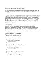
FIGURE 2:
FAT CLUSTER CHAIN
Contents of Data Clusters
File 1
FAT Values
FAT Position
Value
0003h
FFFFh
0004h
0005h
File 2 → Cluster 4
0005h
0007h
File 3 → Cluster 6
0006h
FFFFh
0007h
0008h
0008h
FFFFh
0009h
0000h
File 2, Part 1
“First Cluster” Values from File Entries
File 1 → Cluster 3
File 2, Part 2
File 3
File 2, Part 3
File 2, Part 4
Available Cluster
Note 1:
Two-byte cluster values in this figure are for the FAT16 file system. FAT32 uses four-byte cluster values, as
indicated in Table 6.
The “First Cluster” values in three file entries in the root
directory indicate the start of three files. The FAT
Values demonstrate the links between the files. File 1
and 3 are smaller than the size of a cluster; hence, only
one cluster is assigned to them. The entries in the FAT
that correspond to these files contain only the
End-Of-File (EOF) value.
© 2008 Microchip Technology Inc.
File 2 is larger than three clusters, but smaller than
four; hence, four clusters are assigned to it. Since three
consecutive clusters were not available when File 2
was created, nonconsecutive clusters were assigned
to it; this is called “fragmentation”. Each value in the
FAT for File 2 point to the next cluster in the file. The
last entry in the FAT for File 2 contains the End-Of-File
value.
DS01045B-page 5
AN1045
Directories
Except for the root directory, the directories in this file
system are written in the same way that files are
written. Each directory occupies one or more clusters in
the data section of the partition, and has its own
directory entry and chain of FAT entries. Bit four of the
attribute field in the directory entry of a directory is set,
indicating that the entry belongs to a directory.
Directory names in this library follow the short filename
format (8.3 format). Directories differ from files; they do
not have an extension.
Each directory contains 32-byte directory entries. Two
directory entries, the dot entry and the dot dot entry are
present in every directory except the root directory. The
dot entry is the first entry in any subdirectory. The name
value in this entry is a single dot (2Eh) followed by ten
space characters (20h). The pointer of this entry to the
first cluster of its “file” will actually point to the cluster
that contains the entry itself. The dot dot entry is similar,
except the name contains two dots followed by nine
spaces, and the pointer to the first cluster in the “file”
will point to the directory that contains the entry for the
directory that the dot dot entry is in (the previous
directory).
When the directories are enabled in this library, all file
modification will be done in the Current Working
Directory (CWD). When the card is initialized by calling
FSInit, the CWD is automatically set to the root
directory. After this, the CWD can be changed with the
FSchdir function.
Directory names in a path string are delimited by the
backslash character (\). When denoting a backslash
character in a string, an additional backslash must be
added as part of an escape sequence, as the
backslash is used by C to begin escape sequences.
• If the first character of a path string is a backslash,
the path will be assumed to be specified relative
to the root directory.
• If a path string begins with a directory name, the
path will be assumed to be specified relative to
the current working directory.
• If a dot (.) or dot dot (..) is included in the path as a
directory name, the code will operate using those
directory entries.
For example, if the user changes the CWD to
“.\TEST\..\TEST\..\.\.”, the current working
directory would not change from where it originally
started, assuming that the directory, TEST, exists in
the original directory.
Note:
When hard-coding the string in C, double
backslashes are required. Refer to the API
descriptions of FSmkdir, FSchdir,
FSrmdir and FSgetcwd.
Table 7 provides more examples of path strings.
Follow these conventions when specifying path names
in the directory manipulation functions:
TABLE 7:
EXAMPLE DIRECTORY PATH STRINGS
Path
Meaning
“\”
The root directory.
“.”
Current directory.
“..”
Previous directory.
“ONE”
Directory ONE in the current directory.
“.\ONE”
Directory ONE in the current directory.
“\ONE”
Directory ONE in the root directory.
“..\ONE”
Directory ONE in the previous directory.
“ONE\TWO”
Directory TWO in directory ONE in the current directory.
“\ONE\TWO”
Directory TWO in directory ONE in the root directory.
“ONE\..\TWO”
Directories ONE and TWO in the current directory (this path could be used to create
non-existent directories in the same place using the FATmkdir function).
DS01045B-page 6
© 2008 Microchip Technology Inc.
AN1045
SOFTWARE LIBRARY
User Functions
To manage file and disk manipulation, call functions are
provided in Table 8.
TABLE 8:
FILE AND DISK MANIPULATION FUNCTIONS
Function Name
Description
FSInit
Initializes the card, loads the master boot record (partition information), loads the boot sector
and updates the parameters passed into it with its information.
FSfclose
Updates the file information, writes the remaining entry in and frees the RAM from the heap
that was used to hold the information about that file. This also updates the time-stamp
information for the file.
FSfeof
Verifies if the end of the file has been reached.
FSfopen
Allocates space in the heap for file information. If the file being opened already exists,
FSfopen can open it so that the data would be appended at the end of the file, erase it and
create a new file with the same name to be written to, or simply open it for reading. If the file
does not exist, FSfopen can create it. This function then returns a pointer to the structure in
the heap that contains information for this file.
FSfopenpgm
Opens a file on the SD card and associates an FSFILE structure (stream) with it using
arguments specified in ROM. This function is necessary only on the PIC18 architecture.
FSfread
Reads information from an open file to a buffer. The number of bytes written can be specified
by its parameters. If FSfread is called consecutively on the same open file, the read will
continue from the place it stopped after the previous read. This function returns the number of
data objects read.
FSfseek
Changes the position in a file. When a user calls FSfseek, they specify the base address to
set, which can either be at the beginning or end of the file, or at the current position in the file.
The user also specifies an offset to add to the base (note that if the base address is at the end
of the file, the offset will be subtracted). Hence, if FSfseek is called with the base set to the
beginning of the file and a specified offset of ‘0’, the position would be changed to the first byte
of the file.
FSftell
Returns the current position in the file. The first position in the file is the first byte in the first
sector of the first cluster, which has the value ‘0’. Hence, if a file was created and 2000 bytes
were written to it, FSftell would return the number 1999 if it was called.
FSfwrite
Writes information from a buffer to an open file. The algorithm it uses reads a sector from the
data region of the disk to SRAM, modifies the relevant bytes and then writes the sector back to
the disk. Because each FSfwrite call reads the data first, the ability to open multiple files at a
time is supported. This also means that writing data in larger blocks takes less time than writing
the same data in smaller blocks as fewer sector reads and writes will be needed.
FSremove
Searches for a file based on a filename parameter passed into it. If the file is found, its directory
entry is marked as deleted and its FAT entry is erased.
FSremovepgm
Deletes the file identified by a given filename. If the file is opened with FSfopen, it must be
closed before calling FSremovepgm. The filename must be specified in ROM. This function is
necessary only on the PIC18 architecture.
FSrename
Changes the name of a file or directory. If the pointer passed into this function is NULL, the
name of the current working directory will be changed.
FSrewind
Resets the position of the file to the beginning of the file.
FSmkdir (directory Creates a new subdirectory in the current working directory.
manipulation)
FSchdir (directory Changes the current working directory to the one specified by the user.
manipulation)
FSrmdir (directory Deletes the specified directory. The user may also choose to specify whether subdirectories
manipulation)
and files contained within the deleted directory are removed. If the user does not permit the
function to delete subdirectories, it fails if the user attempts to delete a non-empty directory.
© 2008 Microchip Technology Inc.
DS01045B-page 7
AN1045
TABLE 8:
FILE AND DISK MANIPULATION FUNCTIONS (CONTINUED)
Function Name
Description
FSgetcwd
(directory
manipulation)
Returns the name of the current working directory to the user.
FindFirst
Locates files in the current working directory that meet the name and attribute criteria. A
SearchRec Structure Pointer will be passed into the function. Once a file is located, the filename, file size, create time and date stamp, and attributes fields in the SearchRec structure
will be updated with the correct file information.
FindFirstpgm
Operates in the same manner as the FindFirst function, except the name criteria for the file
to be found will be passed into the function in ROM. This function is necessary only on the
PIC18 architecture.
FindNext
Locates the next file in the current working directory that matches the criteria specified in the
last call of FindFirst or FindFirstpgm. It will then update the SearchRec structure
provided by the user with the file information.
FSformat
Erases the root directory and file allocation table of a card. The user may also call the function
in a mode that causes it to create a new boot sector based on the information in the master
boot record.
FSfprintf
Writes a formatted string to a file. It automatically replaces any format specifiers in the string
with dynamic values from variables passed into the function. Integer promotion must be
enabled in the build options menu when using this function with the PIC18 architecture.
SetClockVars
Used in user-defined Clock mode to manually set the current date and time. This date and time
would be applied to files as they are created or modified.
Library Setup
5.
This section provides a list of customizations that can
be used with this library. Perform the following steps
before compiling a project:
1.
2.
3.
4.
Add the appropriate physical layer file to the
project. Interfaces for the SD card in SPI mode
(SD-SPI.c, SD-SPI.h) and the CompactFlash
card using the PMP module (CF-PMP.c,
CF-PMP.h) or manual bit toggling (CF-Bit
transaction.c, CF-Bit transaction.h)
are provided. Set the appropriate physical layer
header file by including one of the filenames in
FSconfig.h.
Define the system clock frequency in
FSconfig.h.
Users, who want to configure static memory for
file objects should specify the maximum number
of files that are going to be open at any one time
in FSconfig.h.
Users, who want to configure SD SPI interface
should specify the appropriate register names in
SD-SPI.h.
For example, if SPI module 1 is used on PIC24,
change the definition of SPI1CON to SPI1CON1.
If module 2 is used, change the definition to
SPI2CON1.
DS01045B-page 8
6.
7.
PIC18 users should modify the linker file to
include a 512-byte section of RAM that will act
as a buffer for file reads/writes. This buffer is
defined at the top of the physical interface files.
Also create a section in the linker mapped to this
RAM called dataBuffer. Repeat this process
to create a buffer for FAT reads and writes. This
buffer requires a section mapped to the RAM
you allocate called FATBuffer.
Users, who want to configure dynamic memory
to allocate file objects should set the
corresponding preprocessor directive in the
FSconfig.h file to “#if 1”. If PIC18 is used, a
section called, _SRAM_ALLOC_HEAP, must be
created in the linker file that contains enough
memory to contain all the opened file objects.
Each file object is 46 bytes. Due to variation in
the memory allocation algorithm, the allocated
memory size will be larger. This is also true
when using a PIC24. Verify that enough memory
was allocated to the heap. Include the
salloc.c and salloc.h files in the project
when using PIC18. When using dynamic
memory allocation with the PIC24, a heap in the
MPLINK30 tab of the Build Options menu should
be created.
Set the library path and include path (and linker
path, if PIC18) in the General tab of the Build
Options menu.
© 2008 Microchip Technology Inc.
AN1045
8.
Set the required input and output pins in
your physical layer header file (SD-SPI.h,
CF-PMP.h, …).
9. Make sure that all pins used are configured as
digital I/Os, including the PORTB pins set in the
Configuration registers and any pins that could
be analog channels for the A/D converter.
10. Select the appropriate device and language
toolset. The compiled code will be appropriate to
the processor type (PIC18, PIC24F, PIC24H,
dsPIC30 or dsPIC33).
TABLE 9:
11. There are several definitions in FSconfig.h
that can be used to disable option (functionality)
to save code space if these functions are not
required.
To
enable
the
functionality,
uncomment the option definition in the code.
The available options are shown in Table 9:
LIBRARY OPTIONS
Option
Description
ALLOW_WRITES
Enables write functions to write data to the card.
ALLOW_DIRS
Enables directory functions such as, creating, changing, and so on.
Note: Writes must be enabled to use directories.
ALLOW_FORMATS
Enables card formatting function.
Note: Writes must be enabled to use directories.
ALLOW_FILESEARCH
Enables file and directory search functions, such as FindFirst and FindNext.
ALLOW_PGMFUNCTIONS
Enables the pgm functions, such as FSfopenpgm, FSremovepgm and so on for PIC18.
These functions accept parameters passed through ROM (pgm functions) on PIC18.
The pgm functions will not work with other architectures. However, arguments in ROM
can be passed into standard functions (e.g., FSfopen instead of FSfopenpgm) directly
in PIC24, dsPIC30 and dsPIC33 architectures.
ALLOW_FSFPRINTF
Enables FSfprintf function.
Note: Writes must be enabled to use directories.
SUPPORT_FAT32
Enables FAT32 functionality.
12. Uncomment a define to select a Clock mode for
determining file create/modify/access times.
The Increment Time-Stamp mode will set the
times to a static value and will not provide accurate timing values. This mode is useful when file
times are unimportant, as it reduces complexity.
The User-Defined Clock mode will allow the
user to manually set the timing values using the
© 2008 Microchip Technology Inc.
SetClockVars function. The Use Real-Time
Clock mode will set the timing values automatically based on the values in the Real-Time
Clock and Calendar (RTCC) module. This mode
will require the user to enable and configure the
RTCC module, and it is not available in
architectures that do not support RTCC.
DS01045B-page 9
AN1045
FAT16/FAT32 Initialization and File
Creation
The following C18 code example illustrates a basic
sequence of function calls to open a file for reading.
This example initializes the card with the FSInit
function, and then calls FSfopen to create a new file.
Then, the code calls FSfopenpgm, a function which
performs the same function as FSfopen, but accepts
EXAMPLE 1:
ROM parameters. This call opens an existing file in the
Read mode. The code reads one 10-byte object and
five 1-byte objects from the existing file. The example
also describes how the code writes these objects to the
newly created files, and then closes both the files.
Finally, the code deletes the old file. It is important to
close a currently open file before deleting it.
INITIALIZATION AND FILE CREATION FOR PIC18
#include “FSIO.h”
#define bfrsize 5
void main(void)
{
FSFILE *pOldFile, pNewFile;
char myData[20];
char bfr [6];
int bytesRead, bytesWritten;
char newFile[] = “newfile.txt”;
char writeArg = “w”;
// Must initialize the FAT16/FAT32 library. It also initializes SPI and other related
pins.
if( !FSInit() )
// Failed to initialize FAT16 – do something…
return 1; // Card not present or wrong format
// Create a new file
pNewFile = FSfopen (newFile, writeArg);
// Open an existing file to read
pOldFile = FSfopenpgm (“myfile.txt”, “r”);
if ( pOldFile == NULL )
// Either file is not present or card is not present
return 1;
// Read 10 bytes of data from the file.
bytesRead = FSfread((void*)myData, 10, 1, pOldFile);
// read bfrSize (5) items (of size 1 byte). returns items count
bytesRead = FSfread( (void *)bfr, 1, bfrSize, pOldFile );
// Write those fifteen bytes to the new file
bytesWritten = FSfwrite ((void *) myData, 10, 1, pNewFile);
bytesWritten = FSfwrite ((void *) bfr, 1, bfrSize, pNewFile);
// After processing, close the file.
FSfclose( pOldFile );
FSfclose (pNewFile);
//Delete the old file
FSremovepgm (“myfile.txt”);
}
DS01045B-page 10
© 2008 Microchip Technology Inc.
AN1045
Memory Usage
time. The default values provided are for two files
opened in Static Allocation mode. The C18 data
memory value includes a 200h byte stack. The first row
of the table indicates the smallest amount of memory
that the library will use (for Read-Only mode), and each
subsequent row indicates the increase in memory
caused by enabling other functionality.
Table 10 provides the unoptimized memory usage for
the file interface library using the SD-SPI physical layer.
512 bytes of data memory are used for the data buffer
and an additional 512 bytes are used for the file
allocation table buffer. Additional data memory would
be required based on the number of files opened at a
TABLE 10:
FILE I/O LIBRARY MEMORY USAGE(1)
Program Memory
(C30)
Data Memory
(C30)
Program Memory
(C18)
Data Memory
(C18)
All extra functions disabled
(Read-Only mode)
11934 bytes
1454 bytes
11099 bytes
2121 bytes
File search enabled
+1854 bytes
+0 bytes
+2098 bytes
+0 bytes
Write enabled
+6810 bytes
+0 bytes
+7488 bytes
+0 bytes
Format enabled
(write must be enabled)
+2499 bytes
+0 bytes
+2314 bytes
+0 bytes
Directories enabled
(write must be enabled)
+8430 bytes
+78 bytes
+8380 bytes
+90 bytes
+51 bytes
+0 bytes
+118 bytes
+0 bytes
Functions Included
Directories and search are
both enabled
pgm functions enabled
N/A
N/A
+288 bytes
+0 bytes
FSfprintf enabled
+4749 bytes
+0 bytes
+2758 bytes
+0 bytes
FAT32 support enabled
+423 bytes
+4 bytes
+407 bytes
+4 bytes
Note 1:
This is a resource requirement for V1.02. Refer to the ReadMe file for version-specific resource
requirements. This library was compiled using MPLAB® C18 v8.02, v.3.13 and C30 v.3.01 compilers.
Prerequisites
Description of Data Types and Structures
• During sector reads and writes, the card should
not be removed.
• The size of the PIC18 stack might have to be
increased. Otherwise, a stack overflow could
occur when functions are called and the data is
pushed to the stack. If the stack size is increased
in this way, the memory model in the
Project > Build Options > C18 tab must be set
to “Multi-Bank Model”. To change the size of the
stack, the linker script must be modified. An
example of this is given in Appendix A: “The
• DISK – The DISK structure contains information
about the physical disk. Never directly use the
information stored in this structure.
• FILE – The FILE structure contains information
about a file on the disk. Never directly use the
information stored in this structure.
• Types defined in GenericTypedefs.h:
- BYTE – An unsigned char (8 bits)
- WORD – A short int (16 bits)
- SWORD – An unsigned short long (24 bits)
- DWORD – An unsigned long (32 bits)
• SearchRec – The SearchRec structure contains
the name, create time and date stamps, size and
attributes of a file found using the FindFirst,
FindFirstpgm or FindNext function.
PIC18 Linker Script”.
Table 11 provides the contents of the SearchRec
structure.
© 2008 Microchip Technology Inc.
DS01045B-page 11
AN1045
TABLE 11:
CONTENTS OF THE SearchRec STRUCTURE
Element
Function
char filename
The name of the file (NULL terminated)
unsigned char attributes
The file attributes
unsigned long file size
The size of the file in bytes
unsigned long time-stamp
The create time and date of the file
Bits
Value
31:25
Year (0 = 1980, 1 = 1981, …)
24:21
Month (1 = Jan, 12 = Dec)
20:16
Day (1-31)
15:11
Hours (0-23)
10:5
Minutes (0-59)
4:0
Seconds/2 (0-29)
unsigned int entry
The file entry in the current working directory (for internal use only)
char search name
The string that the user searched for (for internal use only)
unsigned char search attr
The file attributes that the user searched for (for internal use only)
unsigned int cwd clus
The cluster number of the directory that the search was performed in (for
internal use only)
unsigned char initialized
Indicates that the SearchRec object has been initialized with search
information by a call from FindFirst (for internal use only)
DS01045B-page 12
© 2008 Microchip Technology Inc.
AN1045
UNSUPPORTED FEATURES
CONCLUSION
Long filenames are not supported.
File creation and storage are undoubtedly useful for
applications that need to store large or small amounts
of data over a long period. By using this application
note and the C18/C30 code provided with it, project
development time can be minimized.
REFERENCES
• SD Card Association –
• CompactFlash® Association –
• The following documents are referenced by this
application note.
- SD Memory Card Specifications, Part 1
“Physical Layer Specification”, Version 1.01,
September 2000
- SD Memory Card Specifications, Part 2 “File
System Specification”, Version 1.0, February
2000
• MultiMediaCard Association –
• PCGuide: FAT File System Disk Volume Structures –
/>• ISO/IEC 9293 –
/>CatalogueDetail?CSNUMBER = 21273
• FAT32 File System Specification –
/>platform/firmware/fatgen.mspx
• From Wikipedia –
/>
© 2008 Microchip Technology Inc.
DS01045B-page 13
AN1045
APPENDIX A:
THE PIC18 LINKER
SCRIPT
This sample linker script reserves three blocks of
memory:
• Specified by section, _SRAM_ALLOC_HEAP
• Specified by section, dataBuffer
• Specified by section, FATBuffer
EXAMPLE A-1:
The heap section need not be reserved if dynamic
memory is not being used to store file objects.
This script contains a 0x200 byte stack. If a stack spans
multiple memory banks, like the Example A-1 script
does, the “Multi-Bank” model should be selected from
the Project Build Options menu.
PIC18 LINKER SCRIPT
// $Id: 18f8722i.lkr,v 1.4 2005/12/19 16:40:18 nairnj Exp $
// File: 18f8722i.lkr
// Sample ICD2 linker script for the PIC18F8722 processor
LIBPATH .
FILES c018i.o
FILES clib.lib
FILES p18f8722.lib
CODEPAGE
CODEPAGE
CODEPAGE
CODEPAGE
CODEPAGE
CODEPAGE
CODEPAGE
NAME=vectors
NAME=page
NAME=debug
NAME=idlocs
NAME=config
NAME=devid
NAME=eedata
START=0x0
START=0x2A
START=0x1FD80
START=0x200000
START=0x300000
START=0x3FFFFE
START=0xF00000
ACCESSBANK NAME=accessram START=0x0
DATABANK
NAME=gpr1
START=0x60
DATABANK
NAME=gpr2
START=0x100
DATABANK
NAME=gpr3
START=0x200
DATABANK
NAME=gpr4
START=0x300
DATABANK
NAME=gpr5
START=0x400
DATABANK
NAME=gpr6
START=0x500
DATABANK
NAME=gpr7
START=0x600
// Allocate 0x200 bytes for the data buffer
DATABANK
NAME=buffer1
START=0x700
// Allocate 0x200 bytes for the FAT buffer
DATABANK
NAME=buffer2
START=0x900
// Allocate 0x200 bytes for the heap
DATABANK
NAME=gpr8
START=0xB00
DATABANK
NAME=gpr9
START=0xC00
DATABANK
NAME=gpr10
START=0xE00
DATABANK
NAME=dbgspr
START=0xEF4
DATABANK
NAME=gpr11
START=0xF00
ACCESSBANK NAME=accesssfr START=0xF60
SECTION
NAME=CONFIG
// Create a heap section
SECTION
NAME=_SRAM_ALLOC_HEAP
// Create the data buffer section
SECTION
NAME=dataBuffer
// Create the FAT buffer section
SECTION
NAME=FATBuffer
END=0x29
END=0x1FD7F
END=0x1FFFF
END=0x200007
END=0x30000D
END=0x3FFFFF
END=0xF003FF
PROTECTED
PROTECTED
PROTECTED
PROTECTED
PROTECTED
PROTECTED
END=0x5F
END=0xFF
END=0x1FF
END=0x2FF
END=0x3FF
END=0x4FF
END=0x5FF
END=0x6FF
END=0x8FF
PROTECTED
END=0xAFF
PROTECTED
END=0xBFF
END=0xDFF
END=0xEF3
END=0xEFF
END=0xF5F
END=0xFFF
PROTECTED
PROTECTED
ROM=config
RAM=gpr8
RAM=buffer1
RAM=buffer2
STACK SIZE=0x200 RAM=gpr9
DS01045B-page 14
© 2008 Microchip Technology Inc.
AN1045
APPENDIX B:
API DETAILS
FSInit
This API initializes the hardware and mounts the card in the library. If the card is not detected, it returns FALSE.
This must be called before calling any other API function. If the card is removed and inserted, the application must
call FSInit to remount the card. To verify if the card is present, call the MediaIsPresent() low-level function.
Syntax
int FSInit(void)
Parameters
None
Return Values
TRUE if card is present and the format is FAT12, FAT16 or FAT32; FALSE otherwise.
Precondition
None
Side Effects
None
EXAMPLE B-1:
FSInit CODE
// Initialize library and detect card
if ( FSInit() != TRUE )
// Failed to initialize FAT16
© 2008 Microchip Technology Inc.
DS01045B-page 15
AN1045
FSfclose
This API closes an opened file.
Syntax
int FSfclose( FSFILE *stream )
Parameters
stream
–
A pointer to a FILE structure obtained from a previous call of FSfopen.
Return Values
Returns 0 on success.
Returns EOF (-1) on failure.
Precondition
FSfopen was called and the stream contains the pointer returned by FSfopen.
Side Effects
None
EXAMPLE B-2:
FSfclose CODE
if( FSfclose( stream ) == EOF )
{
// Failed to close the file
...
}
...
DS01045B-page 16
© 2008 Microchip Technology Inc.
AN1045
FSfeof
This API detects if End-Of-File (EOF) position is reached.
Syntax
int FSfeof( FSFILE *stream )
Parameters
stream
–
Pointer to opened file.
Return Values
Returns non-zero if the End-Of-File (EOF) indicator is reached.
Returns 0 otherwise.
Precondition
File is opened successfully.
Side Effects
None
EXAMPLE B-3:
FSfeof CODE
if (FSfeof (pFile) == 0)
{
// Error
...
}
© 2008 Microchip Technology Inc.
DS01045B-page 17
AN1045
FSfopen
This API opens a file on the card and associates a FILE structure (stream) with it.
Syntax
FSFILE * FSfopen ( const char * fileName, const char *mode )
Parameters
filename –
A NULL terminated char string specifying the filename. This string must be stored in RAM. The
filename must be less than 8 characters, followed by a radix (.), followed by an extension
containing three or lesser characters. The filename cannot contain any directory or drive letter
information.
–
A NULL terminated string specifying the file operation. This string must also be specified in RAM
for PIC18.
mode
The valid strings are:
r
Read-Only
w
Write
If a file with the same name exists, it will be overwritten.
No reads are allowed.
a
Append
If the file exists, the current location will be set to the end of the file;
otherwise, the file will be created.
No reads are allowed.
Return Values
A pointer to an FSFILE structure to identify the file in subsequent operations; NULL if the specified file could not
be opened.
Precondition
FSInit is called.
Side Effects
None
EXAMPLE B-4:
FSfopen CODE
// Create argument strings in RAM and use them to call the function
FSFILE * fPtr;
char [11] name = “myFile.txt”;
char [2] modeArg = “w”;
fPtr = FSfopen( name, modeArg );
DS01045B-page 18
© 2008 Microchip Technology Inc.
AN1045
FSfopenpgm
This API opens a file on the SD card and associates a FSFILE structure (stream) with it using arguments specified
in ROM.
Syntax
FSFILE * FSfopenpgm (const rom char * fileName, const rom char *mode)
Parameters
filename –
mode
–
A NULL terminated char string specifying the filename. This string must be stored in ROM.
The filename must be less than 8 characters, followed by a radix (.), followed by an extension
containing three or less characters. The filename cannot contain any directory or drive letter
information.
A NULL terminated string specifying the file operation. This string must also be specified in ROM.
The valid strings are:
r
Read-Only
w
Write
If a file with the same name exists, it will be overwritten.
No reads are allowed.
a
Append
The file must exist for this operation.
No reads are allowed.
Return Values
A pointer to the FILE structure to identify the file in subsequent operations, NULL if the specified file could not be
opened.
Precondition
FSInit is called.
Side Effects
None
EXAMPLE B-5:
FSfopenpgm CODE
// Create a file called MYFILE.TXT
FSFILE * fPtr;
fPtr = FSfopen( “myfile.txt”, “w”);
© 2008 Microchip Technology Inc.
DS01045B-page 19
AN1045
FSfread
This API reads data from the previously opened file. FSfread reads n items of data, each of length size bytes
from the given file stream. The data is copied to the buffer pointed by ptr. The total number of bytes transferred
is n * size.
Syntax
size_t FSfread( void *ptr, size_t size, size_t n, FSFILE *stream )
Parameters
ptr
–
Pointer to buffer to hold the data read.
size
–
Length of item in bytes.
n
–
Number of items to read.
stream
–
stream pointer to file opened with read (r) mode.
Return Values
On success, FSfread returns the number of items (not bytes) actually read.
On End-Of-File or error it returns ‘0’.
Precondition
File is opened in Read mode.
Side Effects
None
EXAMPLE B-6:
FSfread CODE
...
//Read 100 packets of size 10 bytes each
nItems = FSfread( bfr, 10, 100, pFile );
if( nItems == 0 )
{
// No packet was read
...
}
else if( nItems < 100 )
{
// did not read all 100 packets. Possible EOF
....
}
else
{
//read all 100 packets
...
}
DS01045B-page 20
© 2008 Microchip Technology Inc.
AN1045
FSfseek
This API moves the File Pointer position associated with the stream. The new position is offset bytes from the
file location given by whence.
Syntax
int FSfseek( FSFILE *stream, long offset, int whence )
Parameters
whence –
File location defining the starting point for offset. Must be 0, 1 or 2 as follows:
SEEK_SET
0
File beginning
SEEK_CUR
1
Current File Pointer position
SEEK_END
2
End-Of-File
offset –
Number of bytes away from the starting point defined by whence.
stream –
Pointer to opened file.
Return Values
Return 0 if success.
Returns -1 on error.
Precondition
File is opened successfully.
Side Effects
None
EXAMPLE B-7:
FSfseek CODE
// move 100 bytes forward from the current
position
if( FSfseek( pFile, 100, SEEK_CUR ) !=
0 )
{
...
// handle error condition
}
© 2008 Microchip Technology Inc.
DS01045B-page 21
AN1045
FSftell
This API returns the current position of the File Pointer.
Syntax
long FSftell( FSFILE *stream )
Parameters
stream –
Pointer to opened file.
Return Values
Returns the current File Pointer position on success.
Returns -1 on error.
Precondition
File is opened successfully.
Side Effects
None
EXAMPLE B-8:
FSftell CODE
// get current file position
long pos = FSftell( pFile );
if (pos == -1)
{
...
//handle error condition
}
DS01045B-page 22
© 2008 Microchip Technology Inc.
AN1045
FSfwrite
This API writes data to the previously opened file, FSfwrite, writes n items of data, each of length size bytes to
the given file stream. The data is copied from the buffer pointed to by ptr. The total number of bytes transferred
is n* size.
Syntax
size_t FSfwrite( const void *ptr, size_t size, size_t n, FSFILE *stream )
Parameters
ptr
–
Pointer to buffer holding data to write.
size
–
Length of item in bytes.
n
–
Number of items to write.
stream –
stream pointer to file opened with write (w) or append (a) mode.
Return Values
On successful completion, FSfwrite returns the number of items (not bytes) actually written; on error it returns a
short count or 0.
Precondition
File is opened in Write (w) or Append (a) mode.
Side Effects
None
EXAMPLE B-9:
FSfwrite CODE
if( FSfwrite( ptr, 100, 20, pFile ) != 20 )
{
// not all items were written
...
//handle error condition
}
© 2008 Microchip Technology Inc.
DS01045B-page 23
AN1045
FSremove
This API deletes the file identified by filename. If the file is opened with FSfopen, it must be closed before calling
FSremove. The filename must be specified in the RAM.
Syntax
int FSremove (const char * filename)
Parameters
filename –
A pointer to a NULL terminated string in RAM.
Return Values
Returns 0 on success.
Returns EOF (-1) on failure.
Precondition
FSInit is called successfully.
Side Effects
None
EXAMPLE B-10:
FSremove CODE
// Create a string for the file name in RAM and then deletes the file with that name
char name[] = “myfile.txt”;
if( FSremove(name) == EOF )
{
// error handling
...
}
...
DS01045B-page 24
© 2008 Microchip Technology Inc.
AN1045
FSremovepgm
This API deletes the file identified by filename. If the file has been opened with FSfopen, it must be closed before
calling FSremovepgm. The filename must be specified in ROM.
Syntax
int FSremove (const rom char * filename)
Parameters
filename –
A pointer to a NULL terminated string in ROM.
Return Values
Returns 0 on success.
Returns EOF (-1) on failure.
Precondition
FSInit is called successfully.
Side Effects
None
EXAMPLE B-11:
FSremovepgm CODE
// Deletes MYFILE.TXT
if( FSremovepgm (“myfile.txt”) == EOF )
{
// error handling
...
}
...
© 2008 Microchip Technology Inc.
DS01045B-page 25