AN1050 a technique to increase the frequency resolution of PICmicro® MCU PWM modules
Bạn đang xem bản rút gọn của tài liệu. Xem và tải ngay bản đầy đủ của tài liệu tại đây (407.75 KB, 10 trang )
AN1050
A Technique to Increase the Frequency Resolution of
PICmicro® MCU PWM Modules
Author:
Lucio Di Jasio
Microchip Technology Inc.
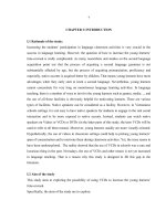
FIGURE 1:
TYPICAL PICMICRO
MICROCONTROLLER
CCP/ECCP MODULE BLOCK
DIAGRAM
INTRODUCTION
Pulse Width Modulation (PWM) modules are
commonly used in many applications to provide an
inexpensive control output method that uses only a few
external components. The PWM signal can be used
directly as a digital signal to drive switches in a power
conversion circuit. Or, it can be filtered using external
components to produce an averaged 'analog' signal
with an output level that is proportional to the duty
cycle. Either way, the duty cycle of the PWM signal
determines the level of system output while the
frequency remains fixed. The typical PICmicro® PWM
module (CCP/ECCP) is ideally designed to support
these common types of applications providing high
duty cycle resolution for a given fixed frequency.
Variable Frequency, Fixed Duty Cycle
Applications
In this application note, we will illustrate a simple
technique that allows all PICmicro PWM modules to
support a different class of applications, including more
specifically several lighting applications, where the
duty cycle is required to be constant and it is the output
frequency that changes in small increments. In
fluorescent and high intensity discharge (HID)
electronic ballasts for example, the frequency variation
is used to control the impedance of an inductor (the
ballast) in series with the lamp. To keep the ballast
inductor small (reducing cost and size), the switching
frequency must be relatively high, in the typical range
of 80kHz to 100kHz. But to allow for an optimal control
of the current in the lamp, the frequency is required to
be controlled in small increments while maintaining a
fixed 50% duty cycle. In other words, these applications
require high frequency resolution and fixed duty cycle.
The typical PICmicro MCU CCP and ECCP module is
based on the structure represented in Figure 1.
© 2006 Microchip Technology Inc.
Duty Cycle Registers
CCPxCON<5:4>
CCPRxL
CCPRxH (Slave)
CCPx Output
R
Comparator
TMR2 (TMR4)
(Note 1)
Comparator
S
Clear Timer,
CCPx pin and
latch D.C.
PR2 (PR4)
Q
Corresponding
TRIS bit
Note 1: The 8-bit TMR2 or TMR4 value is concatenated with
the 2-bit internal Q clock, or 2 bits of the prescaler, to
create the 10-bit time base.
FIGURE 2:
TYPICAL CCP/ECCP TIME
BASE
Period
Duty Cycle
TMR2 (TMR4) = PR2 (PR4)
TMR2 (TMR4) = Duty Cycle
TMR2 (TMR4) = PR2 (TMR4)
Each time the 8-bit timer value equals the Period
Register value a new cycle is started and the PWM
output is set (output high) and the timer reset. Each
time the 8-bit timer value equals the CCP Duty Cycle
register (CCPRxH) the PWM output is cleared (output
low). The necessary flexibility to control the PWM
frequency is provided mainly by the Timer2 module
structure.
DS01050A-page 1
AN1050
FIGURE 3:
TIMER2 MODULE BLOCK DIAGRAM
4
T2OUTPS3:T2OUTPS0
T2CKPS1:T2CKPS0
Set TMR2IF
2
Reset
1:1, 1:4, 1:16
Prescaler
FOSC/4
1:1 to 1:16
Postscaler
TMR2
8
TMR2 Output
(to PWM or MSSP)
TMR2/PR2
Match
Comparator
8
PR2
8
Internal Data Bus
A prescaler is available to reduce the input clock
frequency by three fixed possible ratios of 1:1, 1:4 and
1:16. For the high frequencies required in lighting
applications, the 1:1 ratio must be selected and the
Period Register PR2 (PR4) is used to control the actual
PWM period. The following equation helps determine
the correct timer configuration for a given PWM
frequency and clock frequency pair:
EQUATION 1:
F OSC
PR2 = ------------------------------------------------------- – 1
4 • Prescaler • F PWM
Given a 40 MHz clock signal and a desired 100 kHz
PWM frequency, setting the prescaler to the 1:1 ratio,
we obtain PR2 = 99. Solving Equation 2 for FPWM, we
obtain:
EQUATION 2:
F OSC
F PWM = -----------------------------------------------------------------4 • Prescaler • ( PR2 + 1 )
By incrementing and decrementing PR2 in small
increments around the central period register value, we
can observe that the actual frequency resolution (step)
provided by the CCP/ECCP module is in the range of
1 kHz.
TABLE 1:
CCP/ECCP FREQUENCY
RESOLUTION @ 100 KHZ
PR2
FPWM (Hz)
Step (Hz)
103
97,087
934
102
98,039
952
101
99,009
971
100
100,000
990
99
101,010
1010
98
102,040
1031
97
103,092
1052
DS01050A-page 2
If used in dimmable ballast, this resolution would not be
sufficient to provide a smooth dimming effect,
especially at the low range of the lamp intensity scale
where the human eye is the most sensitive.
Fractional Frequency Increment
In order to provide steps of about 60 Hz with a digital
PWM peripheral (a commonly used reference value),
we would need to increase the clock frequency by a
factor of 16 or 640 MHz, a costly and technically challenging proposition. But there is a simpler and inexpensive solution that can be adopted using the interrupt
mechanism associated to the CCP/ECCP modules and
only a few lines of code. The basic idea consists of considering groups of 16 PWM periods at a time, and alternating between two discrete frequency values (two
contiguous values of the PR2 register). For example
alternating 8 periods with PR2=100 and 8 periods with
PR2 = 99, we will obtain an average frequency of
100,500 Hz. By using other ratios 1:16, 2:16,
3:16...15:16, we will be able to produce 14 intermediate
steps equally spaced by about 64 Hz increments,
between the 100,000 Hz and the 101,010 Hz values. In
a lighting application, the human eye will naturally integrate the luminous output and perceive as if the overall
resolution was in fact increased by a factor of 16.
The simplest algorithm suitable to implement such
mechanism would utilize a counter and perform a
number of cycles, equal to the desired fraction, at the
lower frequency (T1), followed by the complementary
number of cycles at the higher frequency (T2) as
shown in Figure 4.
© 2006 Microchip Technology Inc.
AN1050
FIGURE 4:
ALTERNATING FREQUENCIES IN GROUPS OF 16 PWM CYCLES, 5:16 RATIO
EXAMPLE
0
1
2
3
4
5
6
7
8
9
1
0
1
1
1
2
1
3
1
4
1
5
T1
T1
T1
T1
T1
T2
T2
T2
T2
T2
T2
T2
T2
T2
T2
T2
But this method would add an undesirable strong
second harmonic component to the output signal. A
better result can be obtained by interspersing periods
of the two frequencies as evenly as possible as
depicted in Figure 5.
FIGURE 5:
ALTERNATING FREQUENCIES IN GROUPS OF 16 PWM CYCLES, 5:16 RATIO
EXAMPLE
0
1
2
3
4
5
6
7
8
9
1
0
1
1
1
2
1
3
1
4
1
5
T2
T2
T1
T2
T2
T1
T2
T2
T1
T2
T2
T1
T2
T2
T1
T2
To obtain the evenly spaced distribution of periods, a 4bit accumulator is used and at each cycle the chosen
fractional value (1…15) is added to it. If a carry is
generated the following period will be extended (T1),
otherwise, it will be of base value (T2).
© 2006 Microchip Technology Inc.
DS01050A-page 3
AN1050
A demonstration for the PIC18F1220
The example code provided in Appendix A, illustrates
the simplicity of the solution as implemented in a
general purpose PIC18 microcontroller.
to drive a half bridge ("push-pull") output MOSFET
stage as typically implemented in several ballast
applications.
The PIC18F1220 model was chosen as it represents
one of the smallest and most inexpensive PIC18
devices available and it features an ECCP module that
can produce PWM complementary signals as required
In particular, the fractional counter technique is
implemented in only 12 instructions contained in the
interrupt service routine:
isr
bcf
bcf
movf
addwf
movf
btfss
goto
incf
bsf
setpr2
movwf
CCP1CON,DC1B1
PIR1,TMR2IF
FRAC,W
FACC,F
PERIOD,W
FACC,4
setpr2
WREG,W
CCP1CON,DC1B1
; increase the period by 1
; increase duty by 2xTq to keep it 50%
PR2
; update the next period value
; <<< for demonstration only
btfsc
FACC,4
bsf
OUT
btfss
FACC,4
bcf
OUT
; >>> for demonstration only
bcf
isre
retfie
; clear the interrupt flag
; add the FRAC to the accumulator
; get the base period value in W
; if there was a carry in the fractional accumulator
; signal longer period (T1)
; signal shorter period (T2)
FACC,4
; clear the carry bit
1
; return (fast) restoring the shadow registers
Four additional instructions have been added to drive
one extra output pin (RB0) and help visualize the
alternating sequence of T1 and T2 periods. Pin RB0 is
toggled each time the period of the output signal is
changed as a timing reference.
The graph in Figure 7 has been recorded using the
MPLAB SIM simulator and taking a snapshot of the
Logic Analyzer window.
DS01050A-page 4
© 2006 Microchip Technology Inc.
AN1050
FIGURE 6:
SNAPSHOT OF MPLAB SIM LOGIC ANALYZER WINDOW 16 CYCLES GROUP
The ECCPA waveform represents the ECCP module
output.
FIGURE 7:
Since a ratio of 5:16 was chosen for the demonstration,
we can count 5 x T1 periods of 101 cycles each
(marked by RB0 high) and eleven x T2 periods of 100
cycles each for every group of 16 PWM periods. The
grand total adds up exactly to 1,605 cycles.
MEASURING A T2 PERIOD
© 2006 Microchip Technology Inc.
DS01050A-page 5
AN1050
FIGURE 8:
MEASURING A T1 PERIOD
SUMMARY
This application note shows how to generate a variable
frequency digital signal with good frequency resolution
using a combination of on-chip hardware and software.
The provided code example generates a 100 kHz
signal that can be adjusted in steps of 64 Hz, while
using only 13% of the available CPU cycles thanks to
the use of the PIC18 shadow registers fast interrupt
context save features.
The code presented here can easily be modified to be
utilized on PIC16 (mid-range) microcontrollers
although with a slightly higher CPU overhead and/or to
produce higher frequency resolutions by working on
larger cycle groups.
DS01050A-page 6
© 2006 Microchip Technology Inc.
AN1050
Software License Agreement
The software supplied herewith by Microchip Technology Incorporated (the “Company”) is intended and supplied to you, the
Company’s customer, for use solely and exclusively with products manufactured by the Company.
The software is owned by the Company and/or its supplier, and is protected under applicable copyright laws. All rights are reserved.
Any use in violation of the foregoing restrictions may subject the user to criminal sanctions under applicable laws, as well as to civil
liability for the breach of the terms and conditions of this license.
THIS SOFTWARE IS PROVIDED IN AN “AS IS” CONDITION. NO WARRANTIES, WHETHER EXPRESS, IMPLIED OR STATUTORY, INCLUDING, BUT NOT LIMITED TO, IMPLIED WARRANTIES OF MERCHANTABILITY AND FITNESS FOR A PARTICULAR PURPOSE APPLY TO THIS SOFTWARE. THE COMPANY SHALL NOT, IN ANY CIRCUMSTANCES, BE LIABLE FOR
SPECIAL, INCIDENTAL OR CONSEQUENTIAL DAMAGES, FOR ANY REASON WHATSOEVER.
APPENDIX A:
DEMONSTRATION CODE FOR PIC18F1220
PROCESSOR PIC18F1220
RADIX HEX
; Enhancing the CCP/ECCP frequency resolution for lighting applications
;
; This technique allows a very high frequency PWM (100kHz) signal to be generated
; while providing extremely small frequency increments (60Hz)
;
INCLUDE "p18f1220.inc"
;-----------------------------------------------; timing definitions in kH
#define CLOCK
.10000
; Tcy = 40MHz/4 = 10MHz
#define NFREQ
.100
; nominal frequency 100kHz
#define IPERIOD (CLOCK/NFREQ)-1 ; calculating the base period
#define IFRAC
.5
; 4 bit(0-15)augmented resolution
;-----------------------------------------------; RAM allocation
CBLOCK 0
PERIOD
; integer period
FRAC
; fractional period (0-15)
FACC
; fractional accumulator
ENDC
;-----------------------------------------------; port definitions
#define OUT PORTB,0
; for demonstration only
;-----------------------------------------------ORG 0
; reset vector
resetv
goto init
;-----------------------------------------------ORG 08
; high priority interrupt vector
isr
bcf
CCP1CON,DC1B1
bcf
PIR1,TMR2IF
; clear the interrupt flag
movf
FRAC,W
addwf
FACC,F
; add the FRAC to the accumulator
movf
PERIOD,W
; get the base period value in W
btfss
FACC,4
; if there was a carry in the fractional accumulator
goto
setpr2
incf
bsf
setpr2
movwf
WREG,W
CCP1CON,DC1B1
; increase the period by 1
; increase duty by 2xTq to keep it 50%
PR2
; update the next period value
© 2006 Microchip Technology Inc.
DS01050A-page 7
AN1050
; <<< for demonstration only
btfsc
FACC,4
bsf
OUT
btfss
FACC,4
bcf
OUT
; >>> for demonstration only
bcf
isre
retfie
; signal longer period (T1)
; signal shorter period (T2)
FACC,4
; clear the carry bit
1
; return (fast) restoring the shadow registers
; total ISR time = 13 cycles or 13% MCU load @100kHz/40MHz
;-----------------------------------------------setPWM
; save the required PWM period value
movwf
PERIOD
; set the initial period register value PR2
movwf
PR2
; set the duty cycle to 50%
incf
WREG,W
; PERIOD+1 is the actual total cycle count
bcf
STATUS,C
; divide by 2
rrcf
WREG,F
; shifting right
movwf
CCPR1L
; set the duty cycle
return
;-----------------------------------------------init
; init the output port
movlw
b'00000000'
movwf
TRISB
; disable analog inputs
setf
ADCON1
; set CCP module in PWM mode
movlw
b'00001100'
movwf
CCP1CON
; set the tmr2 to generate the desired frquency and 50% duty
movlw
b'00000100'
; prescale 0, postscale 0, tmr2 ON
movwf
T2CON
; init the period value
movlw
IPERIOD
call
setPWM
; set the PWM and duty cycle
; then init the FRACTIONAL divider for the demo
movlw
IFRAC
movwf
FRAC
; init the fractional period part
; clear the fractional accumulator
clrf
FACC
; clear the accumulator
; then init the interrupt on CCP1/TMR2
bcf
PIR1,TMR2IF
bsf
PIE1,TMR2IE
; init gloabal and peripheral interrupts
bsf
INTCON,PEIE
bsf
INTCON,GIE
;-----------------------------------------------main
goto main
end
DS01050A-page 8
© 2006 Microchip Technology Inc.
Note the following details of the code protection feature on Microchip devices:
•
Microchip products meet the specification contained in their particular Microchip Data Sheet.
•
Microchip believes that its family of products is one of the most secure families of its kind on the market today, when used in the
intended manner and under normal conditions.
•
There are dishonest and possibly illegal methods used to breach the code protection feature. All of these methods, to our
knowledge, require using the Microchip products in a manner outside the operating specifications contained in Microchip’s Data
Sheets. Most likely, the person doing so is engaged in theft of intellectual property.
•
Microchip is willing to work with the customer who is concerned about the integrity of their code.
•
Neither Microchip nor any other semiconductor manufacturer can guarantee the security of their code. Code protection does not
mean that we are guaranteeing the product as “unbreakable.”
Code protection is constantly evolving. We at Microchip are committed to continuously improving the code protection features of our
products. Attempts to break Microchip’s code protection feature may be a violation of the Digital Millennium Copyright Act. If such acts
allow unauthorized access to your software or other copyrighted work, you may have a right to sue for relief under that Act.
Information contained in this publication regarding device
applications and the like is provided only for your convenience
and may be superseded by updates. It is your responsibility to
ensure that your application meets with your specifications.
MICROCHIP MAKES NO REPRESENTATIONS OR
WARRANTIES OF ANY KIND WHETHER EXPRESS OR
IMPLIED, WRITTEN OR ORAL, STATUTORY OR
OTHERWISE, RELATED TO THE INFORMATION,
INCLUDING BUT NOT LIMITED TO ITS CONDITION,
QUALITY, PERFORMANCE, MERCHANTABILITY OR
FITNESS FOR PURPOSE. Microchip disclaims all liability
arising from this information and its use. Use of Microchip
devices in life support and/or safety applications is entirely at
the buyer’s risk, and the buyer agrees to defend, indemnify and
hold harmless Microchip from any and all damages, claims,
suits, or expenses resulting from such use. No licenses are
conveyed, implicitly or otherwise, under any Microchip
intellectual property rights.
Trademarks
The Microchip name and logo, the Microchip logo, Accuron,
dsPIC, KEELOQ, microID, MPLAB, PIC, PICmicro, PICSTART,
PRO MATE, PowerSmart, rfPIC, and SmartShunt are
registered trademarks of Microchip Technology Incorporated
in the U.S.A. and other countries.
AmpLab, FilterLab, Migratable Memory, MXDEV, MXLAB,
SEEVAL, SmartSensor and The Embedded Control Solutions
Company are registered trademarks of Microchip Technology
Incorporated in the U.S.A.
Analog-for-the-Digital Age, Application Maestro, CodeGuard,
dsPICDEM, dsPICDEM.net, dsPICworks, ECAN,
ECONOMONITOR, FanSense, FlexROM, fuzzyLAB,
In-Circuit Serial Programming, ICSP, ICEPIC, Linear Active
Thermistor, Mindi, MiWi, MPASM, MPLIB, MPLINK, PICkit,
PICDEM, PICDEM.net, PICLAB, PICtail, PowerCal,
PowerInfo, PowerMate, PowerTool, REAL ICE, rfLAB,
rfPICDEM, Select Mode, Smart Serial, SmartTel, Total
Endurance, UNI/O, WiperLock and ZENA are trademarks of
Microchip Technology Incorporated in the U.S.A. and other
countries.
SQTP is a service mark of Microchip Technology Incorporated
in the U.S.A.
All other trademarks mentioned herein are property of their
respective companies.
© 2006, Microchip Technology Incorporated, Printed in the
U.S.A., All Rights Reserved.
Printed on recycled paper.
Microchip received ISO/TS-16949:2002 certification for its worldwide
headquarters, design and wafer fabrication facilities in Chandler and
Tempe, Arizona, Gresham, Oregon and Mountain View, California. The
Company’s quality system processes and procedures are for its
PICmicro® 8-bit MCUs, KEELOQ® code hopping devices, Serial
EEPROMs, microperipherals, nonvolatile memory and analog
products. In addition, Microchip’s quality system for the design and
manufacture of development systems is ISO 9001:2000 certified.
© 2006 Microchip Technology Inc.
DS01050A-page 9
WORLDWIDE SALES AND SERVICE
AMERICAS
ASIA/PACIFIC
ASIA/PACIFIC
EUROPE
Corporate Office
2355 West Chandler Blvd.
Chandler, AZ 85224-6199
Tel: 480-792-7200
Fax: 480-792-7277
Technical Support:
Web Address:
www.microchip.com
Australia - Sydney
Tel: 61-2-9868-6733
Fax: 61-2-9868-6755
India - Bangalore
Tel: 91-80-4182-8400
Fax: 91-80-4182-8422
China - Beijing
Tel: 86-10-8528-2100
Fax: 86-10-8528-2104
India - New Delhi
Tel: 91-11-5160-8631
Fax: 91-11-5160-8632
Austria - Wels
Tel: 43-7242-2244-3910
Fax: 43-7242-2244-393
Denmark - Copenhagen
Tel: 45-4450-2828
Fax: 45-4485-2829
China - Chengdu
Tel: 86-28-8676-6200
Fax: 86-28-8676-6599
India - Pune
Tel: 91-20-2566-1512
Fax: 91-20-2566-1513
France - Paris
Tel: 33-1-69-53-63-20
Fax: 33-1-69-30-90-79
China - Fuzhou
Tel: 86-591-8750-3506
Fax: 86-591-8750-3521
Japan - Yokohama
Tel: 81-45-471- 6166
Fax: 81-45-471-6122
Germany - Munich
Tel: 49-89-627-144-0
Fax: 49-89-627-144-44
China - Hong Kong SAR
Tel: 852-2401-1200
Fax: 852-2401-3431
Korea - Gumi
Tel: 82-54-473-4301
Fax: 82-54-473-4302
China - Qingdao
Tel: 86-532-8502-7355
Fax: 86-532-8502-7205
Korea - Seoul
Tel: 82-2-554-7200
Fax: 82-2-558-5932 or
82-2-558-5934
Asia Pacific Office
Suites 3707-14, 37th Floor
Tower 6, The Gateway
Habour City, Kowloon
Hong Kong
Tel: 852-2401-1200
Fax: 852-2401-3431
Atlanta
Alpharetta, GA
Tel: 770-640-0034
Fax: 770-640-0307
Boston
Westborough, MA
Tel: 774-760-0087
Fax: 774-760-0088
Chicago
Itasca, IL
Tel: 630-285-0071
Fax: 630-285-0075
Dallas
Addison, TX
Tel: 972-818-7423
Fax: 972-818-2924
Detroit
Farmington Hills, MI
Tel: 248-538-2250
Fax: 248-538-2260
Kokomo
Kokomo, IN
Tel: 765-864-8360
Fax: 765-864-8387
Los Angeles
Mission Viejo, CA
Tel: 949-462-9523
Fax: 949-462-9608
China - Shanghai
Tel: 86-21-5407-5533
Fax: 86-21-5407-5066
China - Shenyang
Tel: 86-24-2334-2829
Fax: 86-24-2334-2393
China - Shenzhen
Tel: 86-755-8203-2660
Fax: 86-755-8203-1760
China - Shunde
Tel: 86-757-2839-5507
Fax: 86-757-2839-5571
China - Wuhan
Tel: 86-27-5980-5300
Fax: 86-27-5980-5118
China - Xian
Tel: 86-29-8833-7250
Fax: 86-29-8833-7256
Malaysia - Penang
Tel: 60-4-646-8870
Fax: 60-4-646-5086
Philippines - Manila
Tel: 63-2-634-9065
Fax: 63-2-634-9069
Italy - Milan
Tel: 39-0331-742611
Fax: 39-0331-466781
Netherlands - Drunen
Tel: 31-416-690399
Fax: 31-416-690340
Spain - Madrid
Tel: 34-91-708-08-90
Fax: 34-91-708-08-91
UK - Wokingham
Tel: 44-118-921-5869
Fax: 44-118-921-5820
Singapore
Tel: 65-6334-8870
Fax: 65-6334-8850
Taiwan - Hsin Chu
Tel: 886-3-572-9526
Fax: 886-3-572-6459
Taiwan - Kaohsiung
Tel: 886-7-536-4818
Fax: 886-7-536-4803
Taiwan - Taipei
Tel: 886-2-2500-6610
Fax: 886-2-2508-0102
Thailand - Bangkok
Tel: 66-2-694-1351
Fax: 66-2-694-1350
San Jose
Mountain View, CA
Tel: 650-215-1444
Fax: 650-961-0286
Toronto
Mississauga, Ontario,
Canada
Tel: 905-673-0699
Fax: 905-673-6509
DS01050A-page 10
06/08/06
© 2006 Microchip Technology Inc.