AN1145 using a USB flash drive with an embedded host
Bạn đang xem bản rút gọn của tài liệu. Xem và tải ngay bản đầy đủ của tài liệu tại đây (248.92 KB, 14 trang )
AN1145
Using a USB Flash Drive with an Embedded Host
Author:
Kim Otten
Microchip Technology Inc.
INTRODUCTION
USB Flash drives are a popular, simple and inexpensive
method of moving data from one PC to another. Their
use in the embedded market has been limited, however,
due to the requirement that a system must have USB
host capability to communicate with a Flash drive.
In the past, this usually meant that the system needed to
be a PC. However, the introduction of Microchip’s PIC®
microcontrollers with USB embedded host capability
means that embedded systems can now take advantage
of this popular portable media. With the ability to store
data to a USB Flash drive, a PIC microcontroller-based
application now has virtually unlimited data storage.
This application note demonstrates a data logger application that can run on the Explorer 16 Demo Board with
the USB PICtail™ Plus Daughter Board. It implements a
file system with a simple, but powerful, set of commands.
A Note About USB Flash Drives
USB Flash drives come in a wide variety of shapes and
sizes. Many of the Flash drives utilize either the FAT32
or the FAT16 file system and a Small Computer System
Interface (SCSI) command interface. Microchip Application Note AN1045, “Implementing File I/O Functions
Using Microchip’s Memory Disk Drive File System
Library” (DS01045), describes an implementation of this
file system.
© 2008 Microchip Technology Inc.
THE DATA LOGGER APPLICATION
This application stores two types of data:
• Low data rate monitoring. This is done by polling
the on-board potentiometer approximately once
per second. The potentiometer reading and time
and date stamp of the reading are saved to a file
on the Flash drive.
• Higher speed time measurement accuracy. This is
done by reading the temperature sensor every
10 ms. The temperature reading and the count of
elapsed milliseconds are saved to a file on the
Flash drive.
The application also provides a set of simple
commands to interface to the Flash drive (via a serial
terminal interface) and directly manipulate files on the
Flash drive.
Installing the Stack
The USB data logger application is available as part of
Microchip’s complete USB Embedded Host Support
Package (see Appendix A: “Software Discussed in
this Application Note” for more details). To install all
the necessary project files on a host PC, download the
installation file from the Microchip web site and run the
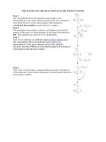
executable installer file. By default, the project and
Stack files will be installed in the directory structure
shown in Figure 1.
DS01145B-page 1
AN1145
FIGURE 1:
DEFAULT DIRECTORY
STRUCTURE FOR USB
EMBEDDED HOST SUPPORT
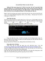
FIGURE 2:
APPLICATION
ARCHITECTURE
Local Hard Drive (C:)
Application
Microchip Solutions
+
+
File System Support (AN1045)
Microchip
+
Common
Generic Microchip
Source Files
+
Include
+
SCSI Command Support
Mass Storage Client Driver (AN1142)
USB
USB Embedded Host Driver
(AN1140/1141)
USB Header Files
Generic Microchip
Header Files
+
USB
+
Documents
Client Driver
Directories
USBConfig.exe
USB Source Files
+
Help
Help Files
+
USB Data Logger
Project Files
Application Architecture
The data logger application is actually a multi-layer
Stack (Figure 2), with different components of
Microchip’s USB Embedded Host Support Package
contributing to different layers. Table 1 shows the
source files used in this application, and which layer
those files implement.
USB EMBEDDED HOST DRIVER
The USB embedded host driver provides generic
support for USB embedded hosts. The interface to this
layer is provided automatically in the mass storage
client driver.
MASS STORAGE CLIENT DRIVER FOR USB
EMBEDDED HOST
The next layer provides the client driver for the mass
storage class, which is required for interfacing with
mass storage devices, such as a USB Flash drive.
Refer to Microchip Application Note AN1142, “USB
Mass Storage Class on an Embedded Host”
(DS01142), for more information about the mass
storage client driver.
FILE SYSTEM AND SCSI COMMAND
SUPPORT
The file system support layer is provided by the file
system library described in Microchip Application Note
AN1045. This application note uses five functions
(Table 2) to interface with the hardware. By replacing
these low-level functions with SCSI commands that
utilize the mass storage client driver for communication, we can use this application note to provide the file
system interface to the USB Flash drive.
Note:
For detailed information about the USB
Embedded Host Mass Storage SCSI Interface API, please refer to the documentation for the USB Embedded Host Library
provided in the Help directory.
For more information about this layer, refer to Microchip
Application Notes AN1140, “USB Embedded Host
Stack” (DS01140), and AN1141, “USB Embedded Host
Stack Programmer’s Guide” (DS01141). Note that it is
not necessary to be familiar with this layer’s operation
or configuration in order to use it with the data logger
application.
DS01145B-page 2
© 2008 Microchip Technology Inc.
AN1145
TABLE 1:
FILES USED FOR THE DATA LOGGER APPLICATION
Layer
USB Embedded Host
Driver
Mass Storage Client Driver
SCSI Command Support
File System Support
(installed as a part of
AN1045)
Application
File Name
usb_host.c
Provides USB embedded host support for all devices.
Does not provide class support.
usb_host.h
Header file with definitions required for USB embedded
hosts. Defines the interface to the USB embedded host
driver.
USBCore.h
Header file with definitions common to both USB
embedded hosts and USB peripherals
usb_host_msd.c
Provides mass storage class support for a USB
embedded host.
usb_host_msd.h
Header file with definitions for USB embedded hosts
supporting the mass storage class. Defines the interface
to the mass storage client driver.
usb_host_msd_scsi.c
Provides SCSI command support for a USB embedded
host utilizing the mass storage client driver.
usb_host_msd_scsi.h
Header file with definitions for USB embedded hosts
using the mass storage client driver and SCSI
commands. This file also includes definitions to link the
AN1045 function name requirements to this
implementation.
FSIO.c
Provides simple commands to perform file activities,
such as open a file, read from a file, write to a file, close
a file, etc.
FSIO.h
Header file with prototypes for the file system functions.
FSDefs.h
Header file with constants and data structures required
by the file system functions.
uart2.c
Provides an interface to UART2 to provide RS-232 input
and output to the application.
uart2.h
Header file for the UART2 functions.
FSConfig.h
Configures the file system library for this application.
usb_config.c
Configures the USB Stack for this application.
Generated by the configuration tool.
usb_config.h
Configures the USB Stack for this application.
Generated by the configuration tool.
system.h
Contains system level constants for libraries to
reference.
usb_data_logger.c
TABLE 2:
Description
Main application code.
FILE SYSTEM INTERFACE FUNCTIONS
Library Function Name
Description
Data Logger Implementation Name
InitIO()
Called when a device is connected.
USBHostMSDSCSIInit()
MediaDetect()
Indicates whether or not media is
currently attached.
USBHostMSDSCSIMediaDetect()
SectorRead()
Reads the indicated sector.
USBHostMSDSCSISectorRead()
SectorWrite()
Writes the indicated sector.
USBHostMSDSCSISectorWrite()
WriteProtectState()
Indicates if the media is
write-protected
USBHostMSDSCSIWriteProtectState()
© 2008 Microchip Technology Inc.
DS01145B-page 3
AN1145
Application Functionality
The data logger application consists of three main
components:
• File Manipulation Capability
• Command Interface
• Data Logging
FILE MANIPULATION CAPABILITY
By utilizing the file system library described in AN1045,
this application provides simple, but powerful, file
manipulation capabilities:
•
•
•
•
•
•
Viewing files in the current directory
Creating and removing directories
Changing the current directory
Copying files and sending files to the UART
Creating files from the command line
Deleting files
Note:
File specification limitations on these
commands, such as wild cards and directory specification, are determined by the
file system library implementation. If the
file system library is updated, these
limitations may change.
COMMAND INTERFACE
The user interfaces with the application by connecting
the Explorer 16 Board’s DB9 serial connector to a PC
running a terminal emulation program, such as
HyperTerminal. The terminal emulation program
should be set to 57600 baud, 8 data bits, no parity,
1 Stop bit and no flow control. Upon initialization, a
banner is displayed, follow by a command prompt:
The command prompt when no Flash drive is inserted
is simply “>”. When a Flash drive is inserted, the drive’s
volume label is read and incorporated into the
command prompt. For example, if a Flash drive with
the volume label “FLASH” is inserted, the command
prompt will be displayed as “FLASH:\>”.
A complete list of file system commands and their
syntax is provided in Table 3. A brief description of the
file system library functions required to implement the
file manipulation commands follows.
CD (Change Directory)
FSchdir() changes the current directory.
COPY (Copy File)
If a source file is specified, this command utilizes the
function, FindFirst(), to locate the file. FSfopen()
opens the source and destination files. FSfread()
reads from the source file, and FSfwrite() writes to
the destination file until FSfeof() indicates the end of
the source file. FSfclose() then closes the source
and destination files.
DEL (Delete File)
FindFirst() locates the file to delete. If the file is
found, FSremove() deletes it.
DIR (Display File Directory)
FindFirst() locates the first file in the directory and
returns information about the file. Then, FindNext()
locates and returns information about additional files in
the directory.
MD (Make Directory)
FSmkdir() creates a directory with the given name.
***** Microchip Explorer vx.yy.zz *****
>
The user may enter commands at the command
prompt. All command entries are converted to upper
case. The user may edit the command as it is being
entered by using the Back Space key. Arrow key editing
(left and right arrows) is not supported.
The application also has a configurable buffer of previous commands. The user may display and scroll through
these commands by using the up arrow and down arrow
keys. The user may edit the displayed command by
using the Back Space key. Arrow key editing (left and
right arrows) of these commands is not supported.
RD (Remove Directory)
FSrmdir() removes the directory with the given
name.
TYPE (Display File)
FindFirst() locates the specified file. FSfopen()
then opens the file. The file contents are read using
FSfread() until FSfeof() indicates the end of the
file. FSfclose() then closes the file.
When the user presses the Enter key, the application
performs the indicated command.
DS01145B-page 4
© 2008 Microchip Technology Inc.
AN1145
TABLE 3:
SUPPORTED FILE SYSTEM COMMANDS
Command Syntax
Description
Requirements
CD <name>
Change current working
directory
COPY <file1>
<file2>
Copy [file1] to [file2]
COPY CON <file>
Create [file] from console
input
User entry while creating the
file is not converted to upper
case. Characters are echoed
as they are entered. No editing is allowed; characters are
written to the file immediately.
Entry is terminated by
entering <Ctrl-Z>.
COPY CON USER.TXT
DATE [yyyy-mmdd]
Display or set the date
All required digits must be
specified.
DATE
DATE 2007-06-22
DEL <file>
Delete file
The file must be in the current DEL FILE.TMP
working directory.
DIR [file]
Display directory
Displays file name,
date/time-stamps and size.
Indicates directories.
HELP | ?
Display help
LOG <POT|TMP>
<file>
Log ADC input to file
MD <name>
Make directory
MD NEWDIR
RD <name>
Remove directory
RD NEWDIR
RESET
<SOFT|HARD>
For development purposes.
SOFT performs a mass
storage Reset; HARD
performs a USB Reset.
Intended for development pur- RESET HARD
poses.
TIME [hh:mm:ss]
Display or set the time
Time is displayed and entered TIME
in 24-hour format. All required TIME 19:30:00
digits must be specified.
TYPE <file>
Sends the contents of the
file to the terminal window
<file> must be in the current
TYPE P1.CSV
working directory. Not
recommended for binary files.
© 2008 Microchip Technology Inc.
At least one space must be
entered after “CD”.
Example
CD
CD
CD
CD
..
\
NEXT
NEXT\ONE
COPY A.TXT B.TXT
DIR
DIR *.TXT
HELP
?
See the sections on data
logging that follow. Logging is
terminated by entering
<Ctrl-C>.
LOG POT P.CSV
LOG TMP T.CSV
DS01145B-page 5
AN1145
LOW DATA RATE DATA LOGGING
Many applications need to monitor and record data with
a time-stamp of when the data sample was obtained.
For data that is monitored on a time scale of seconds,
minutes or hours, the Real-Time Clock and Calendar
(RTCC) provides a simple, useful method of timestamping the data. The DATE and TIME commands are
provided in the command interface to easily set and
display the current date and time of the RTCC.
The LOG command can then be used to perform low
data rate, real-time monitoring of the voltage across the
potentiometer on the Explorer 16 Demo Board. When
the user enters the command, LOG POT <file>, the
application monitors the RTCC to determine when one
second has elapsed. Every time one second passes,
the application performs an analog-to-digital conversion on the potentiometer, which is connected to AN5.
The time-stamps and potentiometer readings are formatted into a text string and stored in a buffer that
matches the size of one media sector. When the buffer
is full, the buffer is written to the Flash drive using the
file name given on the command line.
The Comma Separated Value (.csv) format of the text
string was chosen for ease of import into a spreadsheet
program, such as Microsoft® Excel. It can easily be
modified for import into a custom application.
EXAMPLE 1:
SAMPLE DATA,
POTENTIOMETER MONITOR
2007-08-15,04:29:18,00868
2007-08-15,04:29:19,00869
2007-08-15,04:29:20,00869
Implementation Details
The file system command, FSfopen(), opens the
specified file for writing. Then, the application configures the ADC to manually sample AN5, as shown in
Example 2.
EXAMPLE 2:
A/D CONFIGURATION FOR
POTENTIOMETER MONITOR
AD1CON2 = 0;
//AVdd, AVss, MUXA only
AD1CON3 = 0x0005; //No auto-sample time,
//Tad = 5*Tcy
AD1CHS = 0x5;
//MUXA uses AN5
AD1PCFG = 0;
//Disable digital input
//on AN5
AD1CSSL = 0;
//No scanned inputs
AD1CON1 = 0x8000; //Turn on, manual sample
//and conversion
The application uses the library function, sprintf(), to
place a formatted string containing the time-stamp and
the ADC reading in a buffer. The application doublebuffers the data to allow data to be read and written
simultaneously. When a buffer is full, FSfwrite()
writes the buffer to the Flash drive. FSfclose() closes
the file when the user terminates logging.
HIGH DATA RATE DATA LOGGING
Most real-time data analysis requires that data be
captured at a fixed, high-speed rate, on the order of
milliseconds rather than seconds. While PCs offer
great data analysis tools, they cannot be relied upon for
real-time monitoring, since most operating systems
cannot guarantee a fixed, precise time base. Small
embedded applications can easily be created to monitor data at a fixed, high-speed rate, but they are not
good platforms for performing data analysis. The highspeed data logging example demonstrates how to
easily utilize the best features of both platforms by having the embedded application store the obtained data
to a USB Flash drive.
The LOG command can be used to perform high-speed,
real-time data monitoring of the temperature sensor on
the Explorer 16 Demo Board. When the user enters the
command, LOG TMP <file>, Timer3 is used to trigger
an analog-to-digital conversion on AN4 every 10 ms.
When the conversion completes, an interrupt fires, triggering a routine to format the temperature reading and
time-stamp and store the resulting text string in a buffer
that matches the size of one media sector. When the
buffer is full, the buffer is written to the Flash drive using
the file name given on the command line.
The Comma Separated Value (.csv) format of the text
string was chosen for ease of import into a spreadsheet
program. It can easily be modified for import into a
custom application.
EXAMPLE 3:
SAMPLE DATA,
TEMPERATURE MONITOR
0000000010,00139
0000000020,00131
0000000030,00124
Note:
The time-stamp, which is the elapsed
number of milliseconds shown in the first
column, is included in this example for
readability. For increased monitoring
speed, the time-stamp can be eliminated
from the output, since the interval between
samples is known.
The application determines when one second has
elapsed by reading the current time of the RTCC and
comparing it to the previously read time.
DS01145B-page 6
© 2008 Microchip Technology Inc.
AN1145
Implementation Details
THE USB CONFIGURATION TOOL
The file system command, FSfopen(), opens the
specified file for writing. Then, the application configures the ADC to sample AN4 when Timer3 rolls over,
as shown in Example 4.
The USB data logger application has already been configured by using the graphic USB configuration tool,
USBConfig.exe, located in the installation directory,
\Microchip\USB.
The
configuration
files,
USBConfig.c and USBConfig.h, were generated
and stored in the .\USB Data Logger project
directory.
EXAMPLE 4:
A/D CONFIGURATION FOR
TEMPERATURE MONITOR
AD1CON2 = 0;
//AVdd, AVss, MUXA only
AD1CON3 = 0x1F05; //31 Tad auto-sample,
//Tad = 5*Tcy
AD1CHS = 0x4;
//MUXA uses AN4
AD1PCFG = 0;
//Disable digital input
//on AN4
AD1CSSL = 0;
//No scanned inputs
AD1CON1 = 0x8046; //Turn on, start sampling,
//convert on Timer 3
The following
selected:
1.
2.
Timer3 provides a tick count that is incremented with
every rollover. The application is manually configured
using the labels, MILLISECONDS_PER_TICK,
TIMER_PRESCALER and TIMER_PERIOD, such that
each tick is 10 ms. These labels are located in the file,
system.h.
have
been
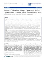
At the Main tab (Figure 3):
a) Device Type: “USB Embedded Host”
b) Ping-Pong Mode: “All endpoints”
At the Host tab (Figure 4):
a) Transfer Type: “Bulk Transfers” only, with
10,000 NAKs allowed (Control Transfers
are also enabled, with dialog text appearing
in grey)
b) Attach Debounce Time: 250 ms
c) Name of Application Event Handler:
USB_ApplicationEventHandler
2: To conserve program and data memory,
transfer events are not used.
3: The number of allowed NAKs may be
adjusted if faster or slower Flash drives
are used.
3.
At the TPL (Targeted Peripheral List) tab
(Figure 5):
a) “Support via Class ID” is selected
b) Client Driver: Mass Storage
c) Class: Mass Storage (0x08)
d) SubClass: SCSI Command Set (0x06)
e) Protocol: Bulk-only Transport (0x50)
f) Initial Configuration: 0
g) Initialization Flags: 0
h) HNP: Not Allowed
Note:
4.
© 2008 Microchip Technology Inc.
options
Note 1: The Attach Debounce Time is increased
from the USB specification minimum of
100 ms to allow for slower devices.
Upon the Timer3 rollover, the ADC automatically
begins a conversion on AN4. When the conversion
completes, the ADC interrupt fires.
The application uses the library function, sprintf(),
to place a formatted string containing the time-stamp
and the ADC reading in a buffer. The application
double-buffers the data to allow data to be read and
written simultaneously. When a buffer is full,
FSfwrite() writes the buffer to the Flash drive.
FSfclose() closes the file when the user terminates
logging.
configuration
While these settings are intended for USB
Flash drives, other mass storage devices
(such as memory card readers) also use
this interface, and will probably work with
this demo application.
At the Mass Storage tab (Figure 6):
a) “Mass Storage Is Used in Host Mode” is
selected
b) Under “Media Interface”, “SCSI Interface” is
selected (the other fields are automatically
populated, and are greyed out)
DS01145B-page 7
AN1145
FIGURE 3:
USB CONFIGURATION TOOL, MAIN TAB
FIGURE 4:
USB CONFIGURATION TOOL, HOST TAB
DS01145B-page 8
© 2008 Microchip Technology Inc.
AN1145
FIGURE 5:
USB CONFIGURATION TOOL, TPL TAB
FIGURE 6:
USB CONFIGURATION TOOL, MASS STORAGE TAB
© 2008 Microchip Technology Inc.
DS01145B-page 9
AN1145
CONCLUSION
REFERENCES
Using Microchip’s USB embedded host capability with
the mass storage class client driver, embedded applications can now read from and write to USB mass storage devices, such as USB Flash drives. This capability
gives embedded applications virtually unlimited data
storage, providing simple, but powerful, connectivity
between the embedded world and the realm of PCs.
For more information on components of the Microchip
USB Embedded Host Support Package, the following
documents are available at the Microchip web site
(www.microchip.com/usb):
• Microchip Application Note AN1045, “Implementing
File I/O Functions Using Microchip’s Memory Disk
Drive File System Library” (DS01045)
• Microchip Application Note AN1140, “USB
Embedded Host Stack” (DS01140)
• Microchip Application Note AN1141, “USB
Embedded Host Stack Programmer’s Guide”
(DS01141)
• Microchip Application Note AN1142, “USB Mass
Storage Class on an Embedded Host” (DS01142)
For more information on USB and embedded host
functionality in general:
• USB Implementers Forum, “Universal Serial Bus
Revision 2.0 Specification”,
/>• USB Implementers Forum, “Requirements and
Recommendations for USB Products with
Embedded Hosts and/or Multiple Receptacles”,
/>
DS01145B-page 10
© 2008 Microchip Technology Inc.
AN1145
APPENDIX A:
SOFTWARE
DISCUSSED IN THIS
APPLICATION NOTE
The USB data logger application is available for download as part of Microchip’s USB Embedded Host
Library. This software library, delivered as a WinZip
archive, contains the source code and support files
required for all layers of the application. Interested
users may download the USB Embedded Host Library
from the Microchip corporate web site, at
www.microchip.com/usb
© 2008 Microchip Technology Inc.
DS01145B-page 11
AN1145
NOTES:
DS01145B-page 12
© 2008 Microchip Technology Inc.
Note the following details of the code protection feature on Microchip devices:
•
Microchip products meet the specification contained in their particular Microchip Data Sheet.
•
Microchip believes that its family of products is one of the most secure families of its kind on the market today, when used in the
intended manner and under normal conditions.
•
There are dishonest and possibly illegal methods used to breach the code protection feature. All of these methods, to our
knowledge, require using the Microchip products in a manner outside the operating specifications contained in Microchip’s Data
Sheets. Most likely, the person doing so is engaged in theft of intellectual property.
•
Microchip is willing to work with the customer who is concerned about the integrity of their code.
•
Neither Microchip nor any other semiconductor manufacturer can guarantee the security of their code. Code protection does not
mean that we are guaranteeing the product as “unbreakable.”
Code protection is constantly evolving. We at Microchip are committed to continuously improving the code protection features of our
products. Attempts to break Microchip’s code protection feature may be a violation of the Digital Millennium Copyright Act. If such acts
allow unauthorized access to your software or other copyrighted work, you may have a right to sue for relief under that Act.
Information contained in this publication regarding device
applications and the like is provided only for your convenience
and may be superseded by updates. It is your responsibility to
ensure that your application meets with your specifications.
MICROCHIP MAKES NO REPRESENTATIONS OR
WARRANTIES OF ANY KIND WHETHER EXPRESS OR
IMPLIED, WRITTEN OR ORAL, STATUTORY OR
OTHERWISE, RELATED TO THE INFORMATION,
INCLUDING BUT NOT LIMITED TO ITS CONDITION,
QUALITY, PERFORMANCE, MERCHANTABILITY OR
FITNESS FOR PURPOSE. Microchip disclaims all liability
arising from this information and its use. Use of Microchip
devices in life support and/or safety applications is entirely at
the buyer’s risk, and the buyer agrees to defend, indemnify and
hold harmless Microchip from any and all damages, claims,
suits, or expenses resulting from such use. No licenses are
conveyed, implicitly or otherwise, under any Microchip
intellectual property rights.
Trademarks
The Microchip name and logo, the Microchip logo, Accuron,
dsPIC, KEELOQ, KEELOQ logo, MPLAB, PIC, PICmicro,
PICSTART, rfPIC, SmartShunt and UNI/O are registered
trademarks of Microchip Technology Incorporated in the
U.S.A. and other countries.
FilterLab, Linear Active Thermistor, MXDEV, MXLAB,
SEEVAL, SmartSensor and The Embedded Control Solutions
Company are registered trademarks of Microchip Technology
Incorporated in the U.S.A.
Analog-for-the-Digital Age, Application Maestro, CodeGuard,
dsPICDEM, dsPICDEM.net, dsPICworks, dsSPEAK, ECAN,
ECONOMONITOR, FanSense, In-Circuit Serial
Programming, ICSP, ICEPIC, Mindi, MiWi, MPASM, MPLAB
Certified logo, MPLIB, MPLINK, mTouch, PICkit, PICDEM,
PICDEM.net, PICtail, PIC32 logo, PowerCal, PowerInfo,
PowerMate, PowerTool, REAL ICE, rfLAB, Select Mode, Total
Endurance, WiperLock and ZENA are trademarks of
Microchip Technology Incorporated in the U.S.A. and other
countries.
SQTP is a service mark of Microchip Technology Incorporated
in the U.S.A.
All other trademarks mentioned herein are property of their
respective companies.
© 2008, Microchip Technology Incorporated, Printed in the
U.S.A., All Rights Reserved.
Printed on recycled paper.
Microchip received ISO/TS-16949:2002 certification for its worldwide
headquarters, design and wafer fabrication facilities in Chandler and
Tempe, Arizona; Gresham, Oregon and design centers in California
and India. The Company’s quality system processes and procedures
are for its PIC® MCUs and dsPIC® DSCs, KEELOQ® code hopping
devices, Serial EEPROMs, microperipherals, nonvolatile memory and
analog products. In addition, Microchip’s quality system for the design
and manufacture of development systems is ISO 9001:2000 certified.
© 2008 Microchip Technology Inc.
DS01145B-page 13
WORLDWIDE SALES AND SERVICE
AMERICAS
ASIA/PACIFIC
ASIA/PACIFIC
EUROPE
Corporate Office
2355 West Chandler Blvd.
Chandler, AZ 85224-6199
Tel: 480-792-7200
Fax: 480-792-7277
Technical Support:
Web Address:
www.microchip.com
Asia Pacific Office
Suites 3707-14, 37th Floor
Tower 6, The Gateway
Harbour City, Kowloon
Hong Kong
Tel: 852-2401-1200
Fax: 852-2401-3431
India - Bangalore
Tel: 91-80-4182-8400
Fax: 91-80-4182-8422
India - New Delhi
Tel: 91-11-4160-8631
Fax: 91-11-4160-8632
Austria - Wels
Tel: 43-7242-2244-39
Fax: 43-7242-2244-393
Denmark - Copenhagen
Tel: 45-4450-2828
Fax: 45-4485-2829
India - Pune
Tel: 91-20-2566-1512
Fax: 91-20-2566-1513
France - Paris
Tel: 33-1-69-53-63-20
Fax: 33-1-69-30-90-79
Japan - Yokohama
Tel: 81-45-471- 6166
Fax: 81-45-471-6122
Germany - Munich
Tel: 49-89-627-144-0
Fax: 49-89-627-144-44
Atlanta
Duluth, GA
Tel: 678-957-9614
Fax: 678-957-1455
Boston
Westborough, MA
Tel: 774-760-0087
Fax: 774-760-0088
Chicago
Itasca, IL
Tel: 630-285-0071
Fax: 630-285-0075
Dallas
Addison, TX
Tel: 972-818-7423
Fax: 972-818-2924
Detroit
Farmington Hills, MI
Tel: 248-538-2250
Fax: 248-538-2260
Kokomo
Kokomo, IN
Tel: 765-864-8360
Fax: 765-864-8387
Los Angeles
Mission Viejo, CA
Tel: 949-462-9523
Fax: 949-462-9608
Santa Clara
Santa Clara, CA
Tel: 408-961-6444
Fax: 408-961-6445
Toronto
Mississauga, Ontario,
Canada
Tel: 905-673-0699
Fax: 905-673-6509
Australia - Sydney
Tel: 61-2-9868-6733
Fax: 61-2-9868-6755
China - Beijing
Tel: 86-10-8528-2100
Fax: 86-10-8528-2104
China - Chengdu
Tel: 86-28-8665-5511
Fax: 86-28-8665-7889
Korea - Daegu
Tel: 82-53-744-4301
Fax: 82-53-744-4302
China - Hong Kong SAR
Tel: 852-2401-1200
Fax: 852-2401-3431
Korea - Seoul
Tel: 82-2-554-7200
Fax: 82-2-558-5932 or
82-2-558-5934
China - Nanjing
Tel: 86-25-8473-2460
Fax: 86-25-8473-2470
Malaysia - Kuala Lumpur
Tel: 60-3-6201-9857
Fax: 60-3-6201-9859
China - Qingdao
Tel: 86-532-8502-7355
Fax: 86-532-8502-7205
Malaysia - Penang
Tel: 60-4-227-8870
Fax: 60-4-227-4068
China - Shanghai
Tel: 86-21-5407-5533
Fax: 86-21-5407-5066
Philippines - Manila
Tel: 63-2-634-9065
Fax: 63-2-634-9069
China - Shenyang
Tel: 86-24-2334-2829
Fax: 86-24-2334-2393
Singapore
Tel: 65-6334-8870
Fax: 65-6334-8850
China - Shenzhen
Tel: 86-755-8203-2660
Fax: 86-755-8203-1760
Taiwan - Hsin Chu
Tel: 886-3-572-9526
Fax: 886-3-572-6459
China - Wuhan
Tel: 86-27-5980-5300
Fax: 86-27-5980-5118
Taiwan - Kaohsiung
Tel: 886-7-536-4818
Fax: 886-7-536-4803
China - Xiamen
Tel: 86-592-2388138
Fax: 86-592-2388130
Taiwan - Taipei
Tel: 886-2-2500-6610
Fax: 886-2-2508-0102
China - Xian
Tel: 86-29-8833-7252
Fax: 86-29-8833-7256
Thailand - Bangkok
Tel: 66-2-694-1351
Fax: 66-2-694-1350
Italy - Milan
Tel: 39-0331-742611
Fax: 39-0331-466781
Netherlands - Drunen
Tel: 31-416-690399
Fax: 31-416-690340
Spain - Madrid
Tel: 34-91-708-08-90
Fax: 34-91-708-08-91
UK - Wokingham
Tel: 44-118-921-5869
Fax: 44-118-921-5820
China - Zhuhai
Tel: 86-756-3210040
Fax: 86-756-3210049
01/02/08
DS01145B-page 14
© 2008 Microchip Technology Inc.