AN1275 KEELOQ® with advanced encryption standard (AES) receiverdecoder
Bạn đang xem bản rút gọn của tài liệu. Xem và tải ngay bản đầy đủ của tài liệu tại đây (137.28 KB, 8 trang )
AN1275
KEELOQ® with Advanced Encryption Standard (AES) Receiver/Decoder
Author:
Enrique Aleman
Microchip Technology Inc.
OVERVIEW
This application note describes a KEELOQ® with AES
code hopping decoder implemented on a Microchip
Mid-range Enhanced Flash MCU (PIC16F886). The
purpose of this implementation is to demonstrate how
KEELOQ code hopping technology can be implemented
with the AES encryption algorithm for even greater
security. This allows for a higher level of security
solutions for keyless entry systems and access control
systems. The software has been designed as a group
of independent modules written in C.
The Advanced Encryption Standard (AES) is a means
of encrypting and decrypting data adopted by the
National Institute of Standards and Technology (NIST)
on October 2, 2000. The algorithm used in AES is
called the Rijndael algorithm after its two designers,
Joan Daemen and Vincent Rijmen of Belgium. AES is
a symmetric block cipher that utilizes a secret key to
encrypt the data. This implementation of AES is based
on a 16-byte block of data and a 16-byte key. It was
also designed to balance speed, code size, and
readability.
KEY FEATURES
The set of modules presented in this application note
implement the following features:
• Source compatible with HI-TECH C® compilers
• Pinout compatible with the KEELOQ 3 Development Kit
• Normal Learn mode
• Learns up to 8 transmitters, using the internal
EEPROM memory of the PIC® microcontroller
• Interrupt driven Radio Receive (PWM) routine
• Compatible with KEELOQ/AES hopping code
encoding with PWM transmission format selected,
operating at TE = 200 µs.
• Automatic synchronization during receive, using
the 8 MHz internal oscillator
• I2C™ slave routines are included so that the
decoder can be designed into a larger control
system.
• LCD routines are included to display decrypted
data and messages.
KEELOQ code hopping creates a unique transmission
on every use by using a cycle counter. The cycle
counter is then used to validate the transmission.
The combined AES/KEELOQ algorithm uses a
programmable 128-bit encryption key unique to each
device to generate 128-bit hopping code. The keylength and code-hopping combination increases the
security for remote control and access systems.
© 2009-2011 Microchip Technology Inc.
DS01275B-page 1
AN1275
MODULES OVERVIEW
The code presented in this application note is
composed of the following basic modules:
AES.c
This file contains the functions and tables of the C version of the AES code.
Aes_keygen.c
This file arranges the received encrypted data into the AES block to calculate the key and
decrypt.
Aes_keygen.h
This file contains the function definitions for AES encryption.
Delay.c
HI-TECH C® delay routines.
delay.h
This file contains the function definitions for delay.c.
I2c.c
This file contains the state machine for I2C™ slave communications.
I2c.h
This file contains the function definitions for I2C.c.
Keeloq_RX1.c
This file contains the incoming transmission receiver routine. It has been modified from the
original KEELOQ® receive routine to accommodate the 168-bit incoming AES transmission.
Keeloq_HW.h
This file contains the hardware definitions for the KEELOQ 3 Development kit.
KeeLoq_RX.h
This file is the variable and function definitions for KeeLoq_RX1.c.
lcd.c
Standard HI-TECH LCD routines.
Lcd.h
Header file lcd.c.
Main.c
This file integrates the modules and contains the program main loop.
Table.c
This file has the EEPROM read and write routines. Saves the learned transmitter information.
Table.h
Header file for table.c.
DS01275B-page 2
© 2009-2011 Microchip Technology Inc.
AN1275
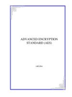
FIGURE 1:
MODULES OVERVIEW
Radio Receiver
KeeLoq_RX1.c
Timer0 Interrupt
- rxi()
LCD.c
LCD Display Routines
Display Learned
Transmitter Information
Rx_Buffer
RF_FULL
Flag
Command Out
Learn
Receive Buffer
Main.c
I2c_receive_buffer
I2c_transmit_buffer
Table.c
- Insert()
- Find()
- IDWrite()
- HopUpdate()
- Clearmem()
Learn Transmitter
I2C.c
Erase Transmitters
2
I C™ Slave Interrupt
- ssp_isr()
Transmitter Info
EEPROM
AES_Keygen.c
-AESKeyGen()
-DecCHK()
-HopCHk()
AES.c
- AESCalcDecodeKey()
- AESDecode()
© 2009-2011 Microchip Technology Inc.
DS01275B-page 3
AN1275
RECEIVER MODULE
The receiver module has been developed around a fast
and independent Interrupt Service Routine (ISR). The
whole receiving routine is implemented as a simple
state machine that operates on a fixed time base. In
this implementation, the ISR is polling the incoming
transmission line every 60 µs. The operation of this
routine is completely transparent to the main program.
After a complete code word of 168 bits has been
properly received and stored in a 22-byte buffer, a
status flag (RF_FULL) is set and the receiver becomes
idle. The main program then is responsible for using
this data in the buffer and clearing the flag to enable the
receiving of a new code word.
In order to account for variations in incoming
transmission timing, the receiver routine constantly
attempts to resynchronize with the first rising edge of
every bit in the incoming code word. This allows the
decoder to operate from the internal RC oscillator. In
doing so, the last rising edge/bit of every code word is
lost (resulting in an effective receive buffer capacity of
168-bit).
FIGURE 2:
TABLE 1:
This time base corresponds to a transmission timing
element (Te) of 200 µs. For other timing elements, the
time base will need to be adjusted; for example, for
Te=400 µs, the time base should be modified to 120 µs.
This is only but an example of how the receiving routine
can be implemented. The designer may want to make
use of other peripherals to write a different version of
the receiver code.
These include:
• Using the INT pin and selectable edge interrupt
source
• Using the Timer1 and CCP module in capture
mode
• Using comparator inputs interrupt
All of these techniques pose different constraints on the
pinout, or the PIC MCU, that can be used.
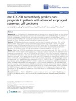
CODE WORD TRANSMISSION FORMAT
KEELOQ®/AES PACKET FORMAT
Plaintext: 40 bits
CRC
(7 bits)
The only resource/peripheral used by this routine is
Timer0 and the associated Overflow Interrupt. This is
available on every mid-range PIC® MCU. Timer0 is
reloaded on overflow, creating a time base of about 60
µs.
VLOW
(1 bit)
Function
Code (4 bits)
Encrypted: 128 bits
Serial Number
(32 bits)
CRC
(16 bits)
Function Code
(16 bits)
Serial Number
(32 bits)
User
(32 bits)
Counter
(32 bits)
Plain text transmitted LSb first. Encrypted portion transmitted MSB first.
KEY GENERATION
Key generation is performed by the AESKeyGen()
function in aes_keygen.c.
To generate the encryption key, the manufacturing key
and the 32-bit serial number (received in plaintext) are
used as inputs to the decoder. The 32-bit serial number
is padded as follows to complete a 128-bit block:
DS01275B-page 4
0xA5A5A5A55A5A5A5A + (32bit-Serial) + 0x00000000
Two functions are called:
AESCalcDecodeKey(key1): this function places the
key in the proper sequence for the decode function.
AESDecode(block,key1): this function performs
the actual decode.
© 2009-2011 Microchip Technology Inc.
AN1275
AES DECRYPTION MODULE
Once the encryption key is generated, it is placed into
key1 to be used for decoding the encrypted data, so
again, the two functions (AESCalcDecodeKey(key1)
and AESDecode(block,key1)) are called.
The decrypted data is now in the block buffer.
TABLE 2:
AES Functions
AESDecrypt
AESCalcDecryptKey
Again, due to the simplicity of the current solution, it is
not possible to selectively delete a transmitter from
memory. The only delete function available is a Bulk
Erase (complete erase of all the memory contents) that
happens when the user presses the Learn button for up
to 10 seconds. (The LED will switch off. At the release
of the button, it will flash once to acknowledge the
delete command).
Uses the key variable to
decrypt the block data.
The block variable is
modified with the
deciphered data. The key
variable contains the
original encrypt key for
that block of data.
Takes the encrypt key
loaded into the key
variable and modifies it to
the decryption key.
TABLE MODULE
One of the major tasks of a decoder is to properly
maintain a database that contains all the unique ID’s
(serial numbers) of the learned transmitters. In most
cases, the database can be as simple as a single table,
which associates those serial numbers to the
synchronization counters. This module implements a
simple “linear list” of records.
Each transmitter learned is assigned a record of 16
bytes (shown in Table 2), where all the relevant
information is stored and regularly updated.
The 32-bit synchronization counter value is stored in
memory twice because it is the most valuable piece of
information in this record. It is continuously updated at
every button press on the remote. When reading the
two stored synchronous values, the decoder should
verify that the two copies match. If not, it can adopt any
safe resync or disable technique required depending
on the desired system security level. The current
implementation limits the maximum number of
transmitters that can be learned to eight. The user can
modify the program to suit more transmitters learned.
This number can be changed to accommodate different
PIC microcontroller models and memory sizes by
modifying the value of the constant MAX_USER.
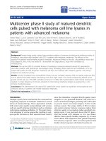
TABLE MODULE
Offset
Data
Description
+0
FCode
Function Code(s) learned
+2
IDHi
Serial Number (Bits 31 ..24)
+3
IDMi1
Serial Number (Bits 23…16)
+4
IDMi0
Serial Number (Bits 15…8)
+5
IDLo
Serial Number (Bits 7..0)
+6
CNTHi
Counter (Bits 31 ..24)
+7
CNTMi1
Counter (Bits 23…16)
+8
CNTMi0
Counter (Bits 15…8)
+9
CNTlO
Counter (Bits 7..0)
+10
CNTHi
Counter Copy (Bits 31 ..24)
+11
CNTMi1
Counter Copy (Bits 23…16)
+12
CNTMi0
Counter Copy (Bits 15…8)
+13
CNTlO
Counter Copy (Bits 7..0)
I2C™ MODULE
An interrupt driven I2C slave state machine is included
in this implementation. The I2C state machine accepts
the Learn and Erase commands as described in
AN1248, “PIC® MCU-Based KEELOQ® Receiver
System Interfaced Via I2C™”.
LCD MODULE
Also included in this implementation are routines for
interfacing with a small LCD module. This permits the
data to be displayed for testing or application purposes.
THE MAIN PROGRAM
The main program is reduced to a few pages of code.
Most of the time, the main loop goes idle waiting for the
receiver to complete reception a full code word.
Double buffering of the receiver is done in RAM, in
order to immediately re-enable the reception of new
codes and increase responsiveness and perceived
range.
The simple “linear list” method employed can be scaled
up to some tens of users. But due to its simplicity, the
time required to recognize a learned transmitter grows
linearly with the length of the table. It is possible to
reach table sizes of thousands of transmitters by
replacing this module with another module that
implements a more sophisticated data structure like a
“Hash Table” or other indexing algorithms.
© 2009-2011 Microchip Technology Inc.
DS01275B-page 5
AN1275
LOADING THE PROJECT
REFERENCES
This project has been developed for the KEELOQ 3
Development Kit base station. The .hex file provided
can be programmed into the base station using a
PICkit™ 2 device programmer.
AN745, “Modular Mid-Range PIC® MCU KEELOQ®
Decoder in C”, (DS00745), Microchip Technology Inc.,
2001.
To load the Project into MPLAB® IDE:
1.
2.
3.
Launch MPLAB IDE, and open the project’s
workspace KEELOQ 3 AES Decoder.mcw.
Verify that the HI-TECH C language tool suite is
selected (Project>Select Language Toolsuite).
In the workspace view, all the source files
mentioned above should be listed.
Because of statutory export license restrictions on
encryption software, the source code listings for the
AES algorithms are not provided here. These
applications may be ordered from Microchip
Technology Inc. through its sales offices, or through the
corporate web site: www.microchip.com\KeeLoq.
C. Gübel, AN821, “Advanced Encryption Standard
Using the PIC16XXX” (DS00821), Microchip
Technology Inc. 2002.
D. Flowers, AN953, “Data Encryption Routines for the
PIC18” (DS00953), Microchip Technology Inc., 2005.
D. Flowers, AN1044 “Data Encryption Routines for
PIC24 and dsPIC® Devices” (DS01044), Microchip
Technology Inc. 2006.
Institute for Applied Information Processing and
Communications, Graz University of Technology, “AES
Lounge” (AES public home page), />E. Aleman, AN1248 “PIC® MCU-Based KEELOQ®
Receiver System Interfaced Via I2C™” (DS01248),
Microchip Technology Inc. 2009.
CONCLUSION
A KEELOQ with AES encryption algorithm provides
maximum security by combining KEELOQ Code
Hopping technology with the 128-bit encryption key
algorithm. The decoding portion works similar to a
standard KEELOQ decoder: the algorithm calculates the
encryption key used to encrypt the transmission; with
this key, the function codes and the cycle counter are
calculated. The cycle counter is then compared to the
currently stored counter value and validated.
ADDITIONAL INFORMATION
Microchip’s Secure Data Products are covered by
some or all of the following:
Code hopping encoder patents issued in European
countries and U.S.A.
Secure learning patents issued in European countries,
U.S.A. and R.S.A.
The implementation presented in this application note
is modular and can be easily modified by the user.
REVISION HISTORY
Revision B (June 2011)
• Added new section Additional Information
• Minor formatting and text changes were
incorporated throughout the document
DS01275B-page 6
© 2009-2011 Microchip Technology Inc.
Note the following details of the code protection feature on Microchip devices:
•
Microchip products meet the specification contained in their particular Microchip Data Sheet.
•
Microchip believes that its family of products is one of the most secure families of its kind on the market today, when used in the
intended manner and under normal conditions.
•
There are dishonest and possibly illegal methods used to breach the code protection feature. All of these methods, to our
knowledge, require using the Microchip products in a manner outside the operating specifications contained in Microchip’s Data
Sheets. Most likely, the person doing so is engaged in theft of intellectual property.
•
Microchip is willing to work with the customer who is concerned about the integrity of their code.
•
Neither Microchip nor any other semiconductor manufacturer can guarantee the security of their code. Code protection does not
mean that we are guaranteeing the product as “unbreakable.”
Code protection is constantly evolving. We at Microchip are committed to continuously improving the code protection features of our
products. Attempts to break Microchip’s code protection feature may be a violation of the Digital Millennium Copyright Act. If such acts
allow unauthorized access to your software or other copyrighted work, you may have a right to sue for relief under that Act.
Information contained in this publication regarding device
applications and the like is provided only for your convenience
and may be superseded by updates. It is your responsibility to
ensure that your application meets with your specifications.
MICROCHIP MAKES NO REPRESENTATIONS OR
WARRANTIES OF ANY KIND WHETHER EXPRESS OR
IMPLIED, WRITTEN OR ORAL, STATUTORY OR
OTHERWISE, RELATED TO THE INFORMATION,
INCLUDING BUT NOT LIMITED TO ITS CONDITION,
QUALITY, PERFORMANCE, MERCHANTABILITY OR
FITNESS FOR PURPOSE. Microchip disclaims all liability
arising from this information and its use. Use of Microchip
devices in life support and/or safety applications is entirely at
the buyer’s risk, and the buyer agrees to defend, indemnify and
hold harmless Microchip from any and all damages, claims,
suits, or expenses resulting from such use. No licenses are
conveyed, implicitly or otherwise, under any Microchip
intellectual property rights.
Trademarks
The Microchip name and logo, the Microchip logo, dsPIC,
KEELOQ, KEELOQ logo, MPLAB, PIC, PICmicro, PICSTART,
PIC32 logo, rfPIC and UNI/O are registered trademarks of
Microchip Technology Incorporated in the U.S.A. and other
countries.
FilterLab, Hampshire, HI-TECH C, Linear Active Thermistor,
MXDEV, MXLAB, SEEVAL and The Embedded Control
Solutions Company are registered trademarks of Microchip
Technology Incorporated in the U.S.A.
Analog-for-the-Digital Age, Application Maestro, chipKIT,
chipKIT logo, CodeGuard, dsPICDEM, dsPICDEM.net,
dsPICworks, dsSPEAK, ECAN, ECONOMONITOR,
FanSense, HI-TIDE, In-Circuit Serial Programming, ICSP,
Mindi, MiWi, MPASM, MPLAB Certified logo, MPLIB,
MPLINK, mTouch, Omniscient Code Generation, PICC,
PICC-18, PICDEM, PICDEM.net, PICkit, PICtail, REAL ICE,
rfLAB, Select Mode, Total Endurance, TSHARC,
UniWinDriver, WiperLock and ZENA are trademarks of
Microchip Technology Incorporated in the U.S.A. and other
countries.
SQTP is a service mark of Microchip Technology Incorporated
in the U.S.A.
All other trademarks mentioned herein are property of their
respective companies.
© 2009-2011, Microchip Technology Incorporated, Printed in
the U.S.A., All Rights Reserved.
Printed on recycled paper.
ISBN: 978-1-61341-252-7
Microchip received ISO/TS-16949:2002 certification for its worldwide
headquarters, design and wafer fabrication facilities in Chandler and
Tempe, Arizona; Gresham, Oregon and design centers in California
and India. The Company’s quality system processes and procedures
are for its PIC® MCUs and dsPIC® DSCs, KEELOQ® code hopping
devices, Serial EEPROMs, microperipherals, nonvolatile memory and
analog products. In addition, Microchip’s quality system for the design
and manufacture of development systems is ISO 9001:2000 certified.
© 2009-2011 Microchip Technology Inc.
DS01275B-page 7
Worldwide Sales and Service
AMERICAS
ASIA/PACIFIC
ASIA/PACIFIC
EUROPE
Corporate Office
2355 West Chandler Blvd.
Chandler, AZ 85224-6199
Tel: 480-792-7200
Fax: 480-792-7277
Technical Support:
/>support
Web Address:
www.microchip.com
Asia Pacific Office
Suites 3707-14, 37th Floor
Tower 6, The Gateway
Harbour City, Kowloon
Hong Kong
Tel: 852-2401-1200
Fax: 852-2401-3431
India - Bangalore
Tel: 91-80-3090-4444
Fax: 91-80-3090-4123
India - New Delhi
Tel: 91-11-4160-8631
Fax: 91-11-4160-8632
Austria - Wels
Tel: 43-7242-2244-39
Fax: 43-7242-2244-393
Denmark - Copenhagen
Tel: 45-4450-2828
Fax: 45-4485-2829
India - Pune
Tel: 91-20-2566-1512
Fax: 91-20-2566-1513
France - Paris
Tel: 33-1-69-53-63-20
Fax: 33-1-69-30-90-79
Japan - Yokohama
Tel: 81-45-471- 6166
Fax: 81-45-471-6122
Germany - Munich
Tel: 49-89-627-144-0
Fax: 49-89-627-144-44
Atlanta
Duluth, GA
Tel: 678-957-9614
Fax: 678-957-1455
Boston
Westborough, MA
Tel: 774-760-0087
Fax: 774-760-0088
Chicago
Itasca, IL
Tel: 630-285-0071
Fax: 630-285-0075
Cleveland
Independence, OH
Tel: 216-447-0464
Fax: 216-447-0643
Dallas
Addison, TX
Tel: 972-818-7423
Fax: 972-818-2924
Detroit
Farmington Hills, MI
Tel: 248-538-2250
Fax: 248-538-2260
Indianapolis
Noblesville, IN
Tel: 317-773-8323
Fax: 317-773-5453
Los Angeles
Mission Viejo, CA
Tel: 949-462-9523
Fax: 949-462-9608
Santa Clara
Santa Clara, CA
Tel: 408-961-6444
Fax: 408-961-6445
Toronto
Mississauga, Ontario,
Canada
Tel: 905-673-0699
Fax: 905-673-6509
Australia - Sydney
Tel: 61-2-9868-6733
Fax: 61-2-9868-6755
China - Beijing
Tel: 86-10-8569-7000
Fax: 86-10-8528-2104
China - Chengdu
Tel: 86-28-8665-5511
Fax: 86-28-8665-7889
Netherlands - Drunen
Tel: 31-416-690399
Fax: 31-416-690340
China - Chongqing
Tel: 86-23-8980-9588
Fax: 86-23-8980-9500
Korea - Seoul
Tel: 82-2-554-7200
Fax: 82-2-558-5932 or
82-2-558-5934
China - Hangzhou
Tel: 86-571-2819-3180
Fax: 86-571-2819-3189
Malaysia - Kuala Lumpur
Tel: 60-3-6201-9857
Fax: 60-3-6201-9859
China - Hong Kong SAR
Tel: 852-2401-1200
Fax: 852-2401-3431
Malaysia - Penang
Tel: 60-4-227-8870
Fax: 60-4-227-4068
China - Nanjing
Tel: 86-25-8473-2460
Fax: 86-25-8473-2470
Philippines - Manila
Tel: 63-2-634-9065
Fax: 63-2-634-9069
China - Qingdao
Tel: 86-532-8502-7355
Fax: 86-532-8502-7205
Singapore
Tel: 65-6334-8870
Fax: 65-6334-8850
China - Shanghai
Tel: 86-21-5407-5533
Fax: 86-21-5407-5066
Taiwan - Hsin Chu
Tel: 886-3-6578-300
Fax: 886-3-6578-370
China - Shenyang
Tel: 86-24-2334-2829
Fax: 86-24-2334-2393
Taiwan - Kaohsiung
Tel: 886-7-213-7830
Fax: 886-7-330-9305
China - Shenzhen
Tel: 86-755-8203-2660
Fax: 86-755-8203-1760
Taiwan - Taipei
Tel: 886-2-2500-6610
Fax: 886-2-2508-0102
China - Wuhan
Tel: 86-27-5980-5300
Fax: 86-27-5980-5118
Thailand - Bangkok
Tel: 66-2-694-1351
Fax: 66-2-694-1350
Spain - Madrid
Tel: 34-91-708-08-90
Fax: 34-91-708-08-91
UK - Wokingham
Tel: 44-118-921-5869
Fax: 44-118-921-5820
China - Xian
Tel: 86-29-8833-7252
Fax: 86-29-8833-7256
China - Xiamen
Tel: 86-592-2388138
Fax: 86-592-2388130
China - Zhuhai
Tel: 86-756-3210040
Fax: 86-756-3210049
DS01275B-page 8
Italy - Milan
Tel: 39-0331-742611
Fax: 39-0331-466781
Korea - Daegu
Tel: 82-53-744-4301
Fax: 82-53-744-4302
05/02/11
© 2009-2011 Microchip Technology Inc.