STUDY, DESIGN AND CONTROL ROBOT PALLETIZER NGHIÊN cứu, THIẾT kế và điều KHIỂN ROBOT gắp HÀNG
Bạn đang xem bản rút gọn của tài liệu. Xem và tải ngay bản đầy đủ của tài liệu tại đây (1.16 MB, 10 trang )
Kỷ yếu hội nghị khoa học và công nghệ toàn quốc về cơ khí - Lần thứ IV
STUDY, DESIGN AND CONTROL ROBOT PALLETIZER
NGHIÊN CỨU, THIẾT KẾ VÀ ĐIỀU KHIỂN ROBOT GẮP HÀNG
Van Linh Tran 1a, Quang Vinh Bui 1a, Tuan Anh Nguyen 1a,
Xuan Hao Nguyen 2b, Cong Bang Pham 2b, Viet Anh Dung Cai 3c
1
Saigon Hi-Tech Park, R&D center, Viet Nam
2
Faculty of Mechanical Engineering, HCMC University of Technology, Viet Nam
3
Faculty of Mechanical Engineering, HCMC University of Technology and Education, Viet Nam
a
{vanlinhkh, buiquangvinh1712, babentanh}@gmail.com
b
{21000883, cbpham}@hcmut.edu.vn, c dungcva@ hcmut.edu.vn
ABSTRACT
Industrial robots are being utilized in many applications due to their stable operation,
high flexibility and precision. This paper presents a type of robot that is useful in applications
of loading and unloading. The robot has 4 degrees of freedom and is structured in such a way
that actuations in horizontal motion and in vertical motion are decoupled. In this paper, a
complete process to design a robot palletizer is highlighted, including conceptual design,
mechanical and electrical design, prototype implementation and accuracy evaluation.
Keywords: industrial robot, palletizer, mechatronic system.
TÓM TẮT
Robot công nghiệp hiện đang được ứng dụng trong nhiều lĩnh vực khác nhau nhờ vào
tính ổn định, khả năng thích ứng linh hoạt và tính chính xác trong vận hành. Bài báo này giới
thiệu về một loại robot được sử dụng phổ biến trong các ứng dụng xếp dỡ. Robot có 4 bậc tự
do, có cấu trúc dẫn động được tách riêng theo phương chuyển động ngang và chuyển động
thẳng đứng. Trong bài báo này, nhóm tác giả xin giới thiệu một quy trình hoàn chỉnh để thiết
kế một robot gắp hàng, bao gồm cả thiết kế ý tưởng, phần cơ điện tử, chế tạo nguyên mẫu và
đánh giá chính xác.
Từ khóa: robot công nghiệp, robot gắp hàng, hệ thống cơ điện tử.
1. INTRODUCTION
Thanks to the development of technology, the robot was invented to release humans
from performing of heavy, dangerous and toxic works. The most common applications of
robots in industry can be listed as spraying paint, welding, assembly, etc.
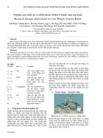
Today, many domestic companies have also been using robots for production jobs as
assembly, welding,... However, in loading and unloading stages as shown in Fig. 1a, manual
handling have been still found quite common. These heavy works would have bad effect on
the health of workers. Therefore, proposing a robot that can be used in automated loading and
unloading systems as illustrated in Fig. 1b is necessary.
Most types of robots in the current market are designed from revolute joints. In this
paper, the robot structure has 4 degrees of freedom (DOF), including 2 revolute joints and 2
prismatic joints. The links were jointed and formed parallelograms of moving rules. The paper
is organized as follows: a conceptual design of 4-DOF robot is presented in section 2. This is
followed by kinematic analysis in section 3. Mechanical design and electrical design are
addressed in section 4 and section 5, respectively. Simulation results to verify the kinematic
analysis are validated in section 6. Experimental results to evaluate accuracy are discussed in
section 7. Finally, section 8 concludes the paper.
130
Kỷ yếu hội nghị khoa học và công nghệ toàn quốc về cơ khí - Lần thứ IV
a)
b)
Figure 1. Loading, unloading crafts and by robot [1]
2. CONCEPTUAL DESIGN
To perform loading and unloading tasks, the robot structure must have abilities to:
Raise and move objects in 3-dimensional space X, Y, Z (from production lines), and
then arrange them onto pallets as illustrated in Fig. 2.
Redirect objects and sort them in a neat order of each column, in multiple interwoven
layers or in a pillow under the circle, as illustrated in Fig. 3.
end-effector
products
Pallets
conveyors
Figure 2. Picking up product from conveyors onto pallets
Figure 3. Typical arrangement of products on pallet [2]
With the given requirements, the robot mechanism must have at least 4 DOFs and is
constrained in such a way that the axis of the end-effector is always kept in the vertical
direction as shown in Fig. 4. In this mechanism, 3 parallelograms can be observed such as
AKLB, AHGB, and BFEC.
L
G
F
B
dc
lx
E
D
C
φ2
lz
P
K
H A
M
dz
N
dx
I
o
φ1
Figure 4. 4-DOF mechanism for robot palletizers
131
Kỷ yếu hội nghị khoa học và công nghệ toàn quốc về cơ khí - Lần thứ IV
To simplify the kinematic analysis, link lengths are designed under the constraint in
Eqn. (1).
𝐼𝐾
=
𝐼𝐿
𝐿𝐵
𝐿𝐶
=
𝐾𝐴
𝐿𝐶
1
=𝑎
(1)
where a is a constant
Combining the parallelogram structures and the constraint in Eqn. (1), then point C will
always in line through A and I, and satisfies Eqn. (2).
𝐴𝐼
𝐴𝑀
=
𝐴𝐶
𝐴𝑁
𝐼𝑀
1
= 𝐶𝑁 = 𝑎−1
(2)
3. KINEMATIC ANALYSIS
Kinematic analysis of robots is to establish the relation between the joint angles / offsets
(φ1, φ2, dx, dz) and the posture of the end-effector (x, y, z, β).
3.1. Forward kinematic
{Q}
YQ
XQ
ZQ
Z0
{0}
Y0
X0
dx
dz
l1
φ1
Figure 5. Assigned frames to locate point P
As discussed in section 2, the position of the end-effector (x, y, z) is only affected by
joint parameters φ1, dx, and dz. [3] Based on the relation of coordinate frames {0} and {Q} in
Fig. 5, together with Eqn. (2), the position of the end-effector P can be derived:
0
𝑥𝑃 = (𝑎𝑑𝑥 + 𝑙𝑥 − 𝑙1 ) cos 𝜑1
{ 𝑦𝑃 = (𝑎𝑑𝑥 + 𝑙𝑥 − 𝑙1 ) sin 𝜑1
0
𝑧𝑃 = −(𝑎 − 1)𝑑𝑧 − 𝑙𝑧
0
(3)
The results in Eqn. (3) show that the position of the end-effector only depends on dx
when it moves horizontally and only depends on dz when it moves vertically.
For the orientation of the end-effector (β), it is only affected by joint angles φ1 and φ2.
Fig. 6 shows a simplified schematic diagram of the robot so that the orientation of frame {2}
which is attached to the end-effector can be described relatively to frame {0} as follows:
𝛽 = 𝜑1 + 𝜑2
Z0
{0}
(4)
Z1
Y0
{1}
Y1
X1
D
X0
φ2
Z2
{2}
φ1
Y2
X2
P
O
Figure 6. Assigned frames to orientate the end-effector
132
Kỷ yếu hội nghị khoa học và công nghệ toàn quốc về cơ khí - Lần thứ IV
3.2. Inverse kinematic
By combining Eqns. (3) and (4), the solution of the inverse kinematic is determined as
follows:
𝑑𝑥 =
2 + 0𝑦 2 −𝑙 +𝑙
√ 0 𝑥𝑃
𝑃 𝑥 1
𝑑𝑧 = −
𝑎
( 0𝑧𝑃 +𝑙𝑧 )
(5)
(𝑎−1)
0
tan 𝜑1 =
𝑦𝑃
0
𝑥𝑃
{ 𝜑2 = 𝛽 − 𝜑1
It is noted that the solution in Eqn. (5) is solvable, however it is only valid when the
geometrical constraint in Eqn. (6) is satisfied.
√𝑑𝑥2 + 𝑑𝑧2 < 𝐼𝐾 + 𝐾𝐴
(6)
4. MECHANICAL DESIGN
This section employs the theoretical basis in section 2 and the results of kinematic
analysis in section 3 to design link lengths of the robot palletizer that encloses a given
workspace as illustrated in Fig. 7. With this desired workspace, link lengths are calculated and
shown in Table 1.
Table 1: Link lengths of the robot palletizer
F
E
G
C
B
K
H
lx
Dimensions
D
lz
A
I
Unit (mm)
P
AB
400
500
L
AH
80
LB
110
BF = BG
80
LC
550
CE
80
EF
440
LI
500
l1
103
lx
85
lz
135
l1
o
400
850
Figure 7. Illustration of robot workspace
Figure 8. 3D CAD model of robot palletizer
Based on data in Table 1, a 3D CAD model of the robot palletizer is designed in
SolidWorks as illustrated in Fig. 8. Then, a prototype of the robot palletizer is fabricated as
demonstrated in Fig. 9.
133
Kỷ yếu hội nghị khoa học và công nghệ toàn quốc về cơ khí - Lần thứ IV
Figure 9. Prototype of the robot palletizer
5. ELECTRICAL DESIGN
5.1. Actuators
In order to drive the robot, 2 DC servo motors, with DCS810 drivers, are employed to
control 2 linear motions (dx, dz) and 2 stepper motors driven by DM556 drivers are employed
to create 2 rotary motions (φ1, φ2). Their wiring diagrams are highlighted in Fig. 10.
VCC
24VDC
GND
VCC
EA+
EA-
DCS810
Driver
24VDC
GND
NC
EB+
EB-
DM556
Driver
NC
E+5V
Gnd VCC Ch-B
Motor -
DC Servo
Motor
Stepping
Motor
B+
B-
EGND
Motor +
A+
A-
Ch-A
Encoder
a) Servo motor and DCS810 driver
b) Stepping motor and DM556 driver
Figure 10. Wiring diagrams
The purpose of using use of two DC motors combined with two stepping motors here is
to help new students get familiar with the controls of various motors. Base on this papers, you
can learn more about the control mechanism of DC servo motor, and stepper motor, since then
there can be the foundation to develop the system on your own later. In addition, the design of
the stepper motor for provides a constant holding torque without the need for the motor to be
powered and provided that the motor is used within its limits, positioning errors don't occur,
since stepper motors have physically pre-defined stations.
5.2. Motion controller board
To carry out combinational operations of the robot, an Arduino Mega 2560 board is
used to synchronize 4 motors. The connection between the drivers and the controller is
demonstrated in general schematic as show in Fig.11.
LED
INDICATION
DC POWER
24V
24V
DCS810
DC SERVO
DCS810
DC SERVO
DM556
STEPPER
MOTOR
DM556
STEPPER
MOTOR
24V
DC DC
CONVERTER
MCU
24V
24V
24V
CONTROL
BUTTONS
Figure 11. General schematic
134
Kỷ yếu hội nghị khoa học và công nghệ toàn quốc về cơ khí - Lần thứ IV
By using the DC DC converter to convert 24V to a lower voltage that allow MCU (here
is the Arduino Mega2560) able work well without heat! Command is given from Control
buttons to MCU to issue required PFM to control these drivers and move the motors to a
specific position that programed before. Led indications are used to display the power status
and errors during operation.
5.3. Pulse Width Speed and Direction Control
The rotational speed of a DC motor is directly proportional to the mean (average)
voltage value on its terminals and the higher this value, up to maximum allowed motor volts,
the faster the motor will rotate. In other words more voltage more speeds. By varying the ratio
between the “ON” (tON) time and the “OFF” (tOFF) time durations, called the “Duty Ratio”,
“Mark/Space Ratio” or “Duty Cycle”, the average value of the motor voltage and hence its
rotational speed can be varied. For simple unipolar drives the duty ratio β is given as:
Figure 12. DC motor duty cycle
and the mean DC output voltage fed to the motor is given as: Vmean = β x Vsupply.
Then by varying the width of pulse a, the motor voltage and hence the power applied to
the motor can be controlled and this type of control is called Pulse Width Modulation or
PWM.
Another way of controlling the rotational speed of the motor is to vary the frequency
(and hence the time period of the controlling voltage) while the “ON” and “OFF” duty ratio
times are kept constant. This type of control is called Pulse Frequency Modulation or PFM
and this is also the method that we used to control the 2 driver DCS810 and DM556 [4].
With pulse frequency modulation, the motor voltage is controlled by applying pulses of
variable frequency for example, at a low frequency or with very few pulses the average
voltage applied to the motor is low, and therefore the motor speed is slow. At a higher
frequency or with many pulses, the average motor terminal voltage is increased and the motor
speed will also increase.
The direction of our motors is determined by the value of DIR input port of drivers.
Changing the value of DIR port will change the rotate direction of motors.
5.4. Orbital motion of Robot Palletizer
Based on the requirements of the actual loading and unloading, the authors will set the
algorithm flowchart for showing the working steps of the robot, then use that to program the
robot to work automatically. The sequence of the robot work is as follows:
Step 1: When button Start is pressed, all the actuators will move to the zero position by
hitting the relays (CT1 = CT2 = CT3 = CT4 = on).
Step 2: Check for existed pallet and products at in the awaiting & loading position.
If:
There is no signal from product (CB1 = off) or no signal from pallet (CB2 = off) or the
pallet was full (CB3 = on) the robot will stop and wait for next command.
Signal from product is received (CB1 = on), signal from pallet is also available (CB2 =
on) and pallet is not full (CB3 = off) then robot move to step 3.
135
Kỷ yếu hội nghị khoa học và công nghệ toàn quốc về cơ khí - Lần thứ IV
Step 3: Sort 6 layers (0
- k is an odd number (k = 1, 3, 5) then sort the products into 3 columns and 2 rows in
order row first then column next until completion (i = 3, j = 2).
- k is even number (k = 2, 4, 6), then sort the products into 2 columns and 3 rows in
order row first column next until completion (i = 2, j = 3).
Step 4: After done with 6 layers the robot will come back to step 2 if there’s no stopped
signal.
Step 5: Ending the cycle of loading and unloading.
In the process robot will stop when received the control signal from button pause.
Loading and unloading process is illustrated in Figure 13 and flowchart algorithm is
illustrated in Fig. 14.
Về chuẩn
Vị trí chuẩn
Lên
Xuống
Vị trí sản
phẩm được
sắp lên pallet
Vị trí sản phẩm
Vị trí pallet
`
a)
b)
Figure 13. Loading and unloading process
a) Gripper head go to zero position then move to products position
b) Gripper head pick up and move product to arranged place on the pallet
C
A
Start
Yes
Initialize
parameters
Stop all actions
No
PAUSE
Start is pressed
No
Check for signals of
product and pallet
Arrange products in
3 columns and 2
rows
I = 3, j = 2
Yes
K is odd number
No
Arrange products in
2 columns and 3
rows
I = 2, j = 3
No
CB1&CB2 are On
CB3 is Off
k = k+1; Reset I, j=0
Yes
Yes
B
Go to zero position
Pickup product at A(xA, yA, zA)
Put onto pallet at P(xP, yP, zP)
No
No
k>6
Yes
ALL CT are on
Yes
A
C
B
No
STOP
Yes
END
Figure 14.Flowchart control algorithm
6. SIMULATION
Motion simulation of the robot is useful to verify the kinematic analysis. A module
Simmechanics link in Matlab is used to convert from CAD models in XML format to
Simulink diagrams in SLX format as seen in Fig. 15a.
136
Kỷ yếu hội nghị khoa học và công nghệ toàn quốc về cơ khí - Lần thứ IV
CS3
B
F
CS3
CS2
CS4
CS4
B
F
CS2
Revolute10
Tay 1-Dung-1
Revolute13
Tay 3-1
CS2
F
F
F
CS3
B
F
CS3
CS2
F
B
B
B
B
Revolute
Noi R3-3
Revolute2
Revolute7
Revolute8
1
B
F
CS2
B
CS4
CS2
F
pos
From
Workspace
B
F
Revolute4
CS3
Revolute9
CS2
X
Conn2
0
Joint Actuator 2
Constant3
Conn3
Revolute12
Thanh truot ngang-1
B
F
CS2
CS3
B
Noi R1-1
Revolute3
Revolute6
Weld1
Conn5
F
Constant4
Revolute5
RootGround
Y
Body Sensor
1
F
Prismatic1
Khung-1
CS2
CS3
CS2
Constant2
Conn4
CS4
B
CS4
Conn1
CS3
F
Joint Actuator 1
1
B
F
B
0
Constant1
Khau Cuoi old-4
Prismatic
Constant0
Noi R2-2
CS3
CS4
CS3
CS2
TAY 2-Ngang-1
CS4
Noi ngang-dung-2
CS5
Revolute11
Thanh truot dung-2
CS2
CS3
Revolute1
0
Joint Actuator 3
Z
Robot
Constant5
tay gap cuoi-1
1
F
B
CS3
CS2
B
F
CS2
CS3
F
B
Env
Constant6
De-1
Weld
Machine
Environment
RootPart
0
Joint Actuator 4
Constant7
a)
b)
Figure 15. Robot model in Matlab and Joint actuators and body sensors attached
t2
t4 = 97,6s
t3
t3 = 72,6s
t1
t1 = 23.8s
t0, t4
t2 = 48.8s
Motion at the joints are generated by blocks of joint actuator. They are also monitored
by blocks of body sensor as illustrated in Fig. 15b. With this block diagram, as the robot is
programmed to move from point to point at specific times and signals from body sensors can
be collected and seen in Fig. 16.
Figure 16. Simulation process and results
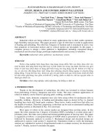
7. EXPERIMENTAL RESULTS
Z3
X0 X1 X2 X3 X4 X5 X6 X7 X8 X9
∆Z
Z2
X0 X1 X2 X3 X4 X5 X6 X7 X8 X9
Z1
X0 X1 X2 X3 X4 X5 X6 X7 X8 X9
Figure 17. Experimental procedure on the horizontal axis
This section will empirically evaluate the issues of decoupling between two actuators in x
direction and z direction. Figure. 18 shows an experimental process to validate vertical errors
while the end-effector moves a distance of 450 mm along x direction at three lifting levels 256
mm, 380 mm, and 500 mm. Experimental results in Table 2 show that vertical errors are from
2,2 mm to 2,26 mm. In addition, error patterns at three altitudes are almost the same.
137
Kỷ yếu hội nghị khoa học và công nghệ toàn quốc về cơ khí - Lần thứ IV
Do similarly, data in Table 3 show experimental results while the end-effector moves a
distance of 500 mm along z direction at three reaching levels 400 mm, 600 mm, and 850 mm.
The results show that horizontal errors are from 3.24 mm to 3.28mm. In addition, error
patterns at three reaching levels are almost the same.
Table 2: Experimental results on the horizontal axis
Position
(mm)
Error, ∆Z
X0
X1
X2
X3
X4
X5
X6
X7
X8
X9
0
0,22
0,48
0,72
0,98
1,22
1,5
1,74
1,98
2,26
1,78
2
2,24
1,72
1,96
2,2
3
Z3 (500)
2
1
0
0
0,26
0,52
0
1
2
0,76
3
4
5
1,02
6
7
1,26
8
9
1,52
3
Z2 (380)
2
1
0
0
0,24
0
0
1
2
0,74
3
4
5
1
6
7
1,24
8
9
1,46
3
Z1 (256)
2
1
0
0
1
2
3
4
5
6
7
8
9
Table 3: Experimental results on the vertical axis
Error, ∆X
Position
X1 (400mm)
X2 (600mm)
X3 (850mm)
Z0
0
0
0
Z1
0,36
0,34
0,38
Z2
0,74
Z3
1,06
0,72
0
1
2
1,08
2
1,42
4
1,82
6
2,16
8
3
Z4
1,44
4
5
Z5
1,78
6
7
Z6
2,18
8
9
Z7
2,52
Z8
Z9
0
2
4
0
0,76
1
1,1
3
1,46
5
2
3
4
5
1,8
7
9
0
1
6
7
2,18
0
2
4
8
9
2,5
2,54
2,88
2,9
2,88
3,24
3,26
3,28
0
2
4
CONCLUSIONS
The paper proposed a type 4-DOF robots based on parallelogram structures. A
prototype has been developed to verify its decoupled motions and accuracy. The experimental
results show that the vertical error is 2.26 mm and horizontal error is 3.28 mm within the
138
Kỷ yếu hội nghị khoa học và công nghệ toàn quốc về cơ khí - Lần thứ IV
investigated area of 450 mm × 500 mm. These values are quite large but acceptable for
loading and unloading applications.
REFERENCES
[1] Patrik Gustafsson-Skoglund,Karl Södereng. Container Unloading using Robotized
Palletizing, M. A. thesis, Chalmers University Of Technology, Sweden, 2012
[2] Michael G. Kay, Material Handling Equipment, North Carolina State University
[3] Ph. D. Phạm Công Bằng, Bài giảng Robot công nghiệp, University of Technology
[4] />AUTHOR’S INFORMATION
1.
Van Linh Tran, Quang Vinh Bui, Tuan Anh Nguyen - Saigon Hi-Tech Park, R&D
center, Viet Nam - {vanlinhkh, buiquangvinh1712, babentanh}@gmail.com
2.
Xuan Hao Nguyen, Cong Bang Pham - Faculty of ME, HCMC, Viet Nam - {21000883,
cbpham}@hcmut.edu.vn
3.
Viet Anh Dung Cai - Faculty of ME, HCMUTE, Viet Nam - dungcva@ hcmut.edu.vn
139