Intelligent autonomous robotics a robot soccer case study
Bạn đang xem bản rút gọn của tài liệu. Xem và tải ngay bản đầy đủ của tài liệu tại đây (1.86 MB, 166 trang )
MOBK082-FM
MOBK082-Stones.cls
June 29, 2007
9:7
Intelligent Autonomous Robotics
A Robot Soccer Case Study
i
MOBK082-FM
MOBK082-Stones.cls
June 29, 2007
9:7
ii
MOBK082-FM
MOBK082-Stones.cls
June 29, 2007
9:7
iii
Synthesis Lectures on Artificial
Intelligence and Machine Learning
Editors
Ronald J. Brachman, Yahoo Research
Tom Dietterich, Oregon State University
Intelligent Autonomous Robotics
Peter Stone
2007
MOBK082-FM
MOBK082-Stones.cls
June 29, 2007
9:7
Copyright © 2007 by Morgan & Claypool
All rights reserved. No part of this publication may be reproduced, stored in a retrieval system, or transmitted in
any form or by any means—electronic, mechanical, photocopy, recording, or any other except for brief quotations
in printed reviews, without the prior permission of the publisher.
Intelligent Autonomous Robotics
Peter Stone, The University of Texas at Austin
www.morganclaypool.com
ISBN: 1598291262
ISBN: 9781598291261
paperback
paperback
ISBN: 1598291270
ISBN: 9781598291278
ebook
ebook
DOI: 10.2200/S00090ED1V01Y200705AIM001
A Publication in the Morgan & Claypool Publishers’ series
SYNTHESIS LECTURES ON ARTIFICIAL INTELLIGENCE AND MACHINE LEARNING #1
Lecture #1
Series Editors : Ronald Brachman, Yahoo! Research and Thomas G. Dietterich, Oregon State University
First Edition
10 9 8 7 6 5 4 3 2 1
iv
MOBK082-FM
MOBK082-Stones.cls
June 29, 2007
9:7
Intelligent Autonomous Robotics
A Robot Soccer Case Study
Peter Stone
The University of Texas at Austin
SYNTHESIS LECTURES ON ARTIFICIAL INTELLIGENCE AND MACHINE
LEARNING #1
M
&C
Morgan
&Claypool
v
Publishers
MOBK082-FM
MOBK082-Stones.cls
June 29, 2007
9:7
vi
ABSTRACT
Robotics technology has recently advanced to the point of being widely accessible for relatively
low-budget research, as well as for graduate, undergraduate, and even secondary and primary
school education. This lecture provides an example of how to productively use a cutting-edge
advanced robotics platform for education and research by providing a detailed case study with
the Sony AIBO robot, a vision-based legged robot. The case study used for this lecture is the
UT Austin Villa RoboCup Four-Legged Team. This lecture describes both the development
process and the technical details of its end result. The main contributions of this lecture are
(i) a roadmap for new classes and research groups interested in intelligent autonomous robotics
who are starting from scratch with a new robot, and (ii) documentation of the algorithms
behind our own approach on the AIBOs with the goal of making them accessible for use on
other vision-based and/or legged robot platforms.
KEYWORDS
Autonomous robots, Legged robots, Multi-Robot Systems, Educational robotics, Robot soccer,
RoboCup
ACKNOWLEDGMENT
This lecture is based on the work and writing of many people, all from the UT Austin Villa
RoboCup team. A significant amount of material is from our team technical report written
after the 2003 RoboCup competition and written in collaboration with Kurt Dresner, Selim T.
Erdo Erdo˘gan, Peggy Fidelman, Nicholas K. Jong, Nate Kohl, Gregory Kuhlmann, Ellie Lin,
Mohan Sridharan, Daniel Stronger, and Gurushyam Hariharan [78]. Some material from the
team’s 2004, 2005, and 2006 technical reports, co-authored with a subset of the above people
plus Tekin Meric¸li and Shao-en Yu, is also included [79, 80, 81]. This research is supported
in part by NSF CAREER award IIS-0237699, ONR YIP award N00014-04-1-0545, and
DARPA grant HR0011-04-1-0035.
MOBK082-FM
MOBK082-Stones.cls
June 29, 2007
9:7
vii
Contents
1.
Introduction . . . . . . . . . . . . . . . . . . . . . . . . . . . . . . . . . . . . . . . . . . . . . . . . . . . . . . . . . . . . . . . . . . 1
2.
The Class . . . . . . . . . . . . . . . . . . . . . . . . . . . . . . . . . . . . . . . . . . . . . . . . . . . . . . . . . . . . . . . . . . . . . 5
3.
Initial Behaviors. . . . . . . . . . . . . . . . . . . . . . . . . . . . . . . . . . . . . . . . . . . . . . . . . . . . . . . . . . . . . . .7
4.
Vision . . . . . . . . . . . . . . . . . . . . . . . . . . . . . . . . . . . . . . . . . . . . . . . . . . . . . . . . . . . . . . . . . . . . . . . . 9
4.1 Camera Settings . . . . . . . . . . . . . . . . . . . . . . . . . . . . . . . . . . . . . . . . . . . . . . . . . . . . . . . . 10
4.2 Color Segmentation . . . . . . . . . . . . . . . . . . . . . . . . . . . . . . . . . . . . . . . . . . . . . . . . . . . . . 11
4.3 Region Building and Merging . . . . . . . . . . . . . . . . . . . . . . . . . . . . . . . . . . . . . . . . . . . . 15
4.4 Object Recognition with Bounding Boxes . . . . . . . . . . . . . . . . . . . . . . . . . . . . . . . . . 17
4.5 Position and Bearing of Objects . . . . . . . . . . . . . . . . . . . . . . . . . . . . . . . . . . . . . . . . . . 22
4.6 Visual Opponent Modeling . . . . . . . . . . . . . . . . . . . . . . . . . . . . . . . . . . . . . . . . . . . . . . 23
5.
Movement . . . . . . . . . . . . . . . . . . . . . . . . . . . . . . . . . . . . . . . . . . . . . . . . . . . . . . . . . . . . . . . . . . . 27
5.1 Walking . . . . . . . . . . . . . . . . . . . . . . . . . . . . . . . . . . . . . . . . . . . . . . . . . . . . . . . . . . . . . . . . 27
5.1.1 Basics . . . . . . . . . . . . . . . . . . . . . . . . . . . . . . . . . . . . . . . . . . . . . . . . . . . . . . . . . . . 27
5.1.2 Forward Kinematics . . . . . . . . . . . . . . . . . . . . . . . . . . . . . . . . . . . . . . . . . . . . . . 28
5.1.3 Inverse Kinematics . . . . . . . . . . . . . . . . . . . . . . . . . . . . . . . . . . . . . . . . . . . . . . . 29
5.1.4 General Walking Structure . . . . . . . . . . . . . . . . . . . . . . . . . . . . . . . . . . . . . . . 32
5.1.5 Omnidirectional Control . . . . . . . . . . . . . . . . . . . . . . . . . . . . . . . . . . . . . . . . . 33
5.1.6 Tilting the Body Forward. . . . . . . . . . . . . . . . . . . . . . . . . . . . . . . . . . . . . . . . .35
5.1.7 Tuning the Parameters . . . . . . . . . . . . . . . . . . . . . . . . . . . . . . . . . . . . . . . . . . . 36
5.1.8 Odometry Calibration . . . . . . . . . . . . . . . . . . . . . . . . . . . . . . . . . . . . . . . . . . . . 36
5.2 General Movement . . . . . . . . . . . . . . . . . . . . . . . . . . . . . . . . . . . . . . . . . . . . . . . . . . . . . . 37
5.2.1 Movement Module . . . . . . . . . . . . . . . . . . . . . . . . . . . . . . . . . . . . . . . . . . . . . . 37
5.2.2 Movement Interface . . . . . . . . . . . . . . . . . . . . . . . . . . . . . . . . . . . . . . . . . . . . . 40
5.2.3 High-Level Control . . . . . . . . . . . . . . . . . . . . . . . . . . . . . . . . . . . . . . . . . . . . . . 43
5.3 Learning Movement Tasks . . . . . . . . . . . . . . . . . . . . . . . . . . . . . . . . . . . . . . . . . . . . . . . 44
5.3.1 Forward Gait . . . . . . . . . . . . . . . . . . . . . . . . . . . . . . . . . . . . . . . . . . . . . . . . . . . . 44
5.3.2 Ball Acquisition . . . . . . . . . . . . . . . . . . . . . . . . . . . . . . . . . . . . . . . . . . . . . . . . . 45
6.
Fall Detection. . . . . . . . . . . . . . . . . . . . . . . . . . . . . . . . . . . . . . . . . . . . . . . . . . . . . . . . . . . . . . . .47
MOBK082-FM
MOBK082-Stones.cls
viii
June 29, 2007
9:7
INTELLIGENT AUTONOMOUS ROBOTICS
7.
Kicking . . . . . . . . . . . . . . . . . . . . . . . . . . . . . . . . . . . . . . . . . . . . . . . . . . . . . . . . . . . . . . . . . . . . . . 49
7.1 Creating the Critical Action . . . . . . . . . . . . . . . . . . . . . . . . . . . . . . . . . . . . . . . . . . . . . . 50
7.2 Integrating the Critical Action into the Walk . . . . . . . . . . . . . . . . . . . . . . . . . . . . . . 51
8.
Localization . . . . . . . . . . . . . . . . . . . . . . . . . . . . . . . . . . . . . . . . . . . . . . . . . . . . . . . . . . . . . . . . . 53
8.1 Background. . . . . . . . . . . . . . . . . . . . . . . . . . . . . . . . . . . . . . . . . . . . . . . . . . . . . . . . . . . . .54
8.1.1 Basic Monte Carlo Localization . . . . . . . . . . . . . . . . . . . . . . . . . . . . . . . . . . . 55
8.1.2 MCL for Vision-Based Legged Robots . . . . . . . . . . . . . . . . . . . . . . . . . . . . 56
8.2 Enhancements to the Basic Approach . . . . . . . . . . . . . . . . . . . . . . . . . . . . . . . . . . . . . 57
8.2.1 Landmark Histories . . . . . . . . . . . . . . . . . . . . . . . . . . . . . . . . . . . . . . . . . . . . . . 57
8.2.2 Distance-Based Updates . . . . . . . . . . . . . . . . . . . . . . . . . . . . . . . . . . . . . . . . . . 59
8.2.3 Extended Motion Model . . . . . . . . . . . . . . . . . . . . . . . . . . . . . . . . . . . . . . . . . 59
8.3 Experimental Setup and Results . . . . . . . . . . . . . . . . . . . . . . . . . . . . . . . . . . . . . . . . . . 60
8.3.1 Simulator . . . . . . . . . . . . . . . . . . . . . . . . . . . . . . . . . . . . . . . . . . . . . . . . . . . . . . . 60
8.3.2 Experimental Methodology . . . . . . . . . . . . . . . . . . . . . . . . . . . . . . . . . . . . . . . 60
8.3.3 Test for Accuracy and Time . . . . . . . . . . . . . . . . . . . . . . . . . . . . . . . . . . . . . . 61
8.3.4 Test for Stability . . . . . . . . . . . . . . . . . . . . . . . . . . . . . . . . . . . . . . . . . . . . . . . . . 63
8.3.5 Extended Motion Model . . . . . . . . . . . . . . . . . . . . . . . . . . . . . . . . . . . . . . . . . 64
8.3.6 Recovery . . . . . . . . . . . . . . . . . . . . . . . . . . . . . . . . . . . . . . . . . . . . . . . . . . . . . . . . 65
8.4 Localization Summary . . . . . . . . . . . . . . . . . . . . . . . . . . . . . . . . . . . . . . . . . . . . . . . . . . . 66
9.
Communication . . . . . . . . . . . . . . . . . . . . . . . . . . . . . . . . . . . . . . . . . . . . . . . . . . . . . . . . . . . . . . 69
9.1 Initial Robot-to-Robot Communication . . . . . . . . . . . . . . . . . . . . . . . . . . . . . . . . . . . 69
9.2 Message Types . . . . . . . . . . . . . . . . . . . . . . . . . . . . . . . . . . . . . . . . . . . . . . . . . . . . . . . . . . 70
9.3 Knowing Which Robots Are Communicating . . . . . . . . . . . . . . . . . . . . . . . . . . . . . . 70
9.4 Determining When A Teammate Is “Dead” . . . . . . . . . . . . . . . . . . . . . . . . . . . . . . . 71
9.5 Practical Results. . . . . . . . . . . . . . . . . . . . . . . . . . . . . . . . . . . . . . . . . . . . . . . . . . . . . . . . .71
10.
General Architecture . . . . . . . . . . . . . . . . . . . . . . . . . . . . . . . . . . . . . . . . . . . . . . . . . . . . . . . . . 73
11.
Global Map . . . . . . . . . . . . . . . . . . . . . . . . . . . . . . . . . . . . . . . . . . . . . . . . . . . . . . . . . . . . . . . . . . 75
11.1 Maintaining Location Data . . . . . . . . . . . . . . . . . . . . . . . . . . . . . . . . . . . . . . . . . . . . . . 75
11.2 Information from Teammates . . . . . . . . . . . . . . . . . . . . . . . . . . . . . . . . . . . . . . . . . . . . 76
11.3 Providing a High-Level Interface . . . . . . . . . . . . . . . . . . . . . . . . . . . . . . . . . . . . . . . . . 78
12.
Behaviors . . . . . . . . . . . . . . . . . . . . . . . . . . . . . . . . . . . . . . . . . . . . . . . . . . . . . . . . . . . . . . . . . . . . 79
12.1 Goal Scoring . . . . . . . . . . . . . . . . . . . . . . . . . . . . . . . . . . . . . . . . . . . . . . . . . . . . . . . . . . . 79
12.1.1 Initial Solution . . . . . . . . . . . . . . . . . . . . . . . . . . . . . . . . . . . . . . . . . . . . . . . . . . 79
MOBK082-FM
MOBK082-Stones.cls
June 29, 2007
9:7
CONTENTS
12.1.2 Incorporating Localization . . . . . . . . . . . . . . . . . . . . . . . . . . . . . . . . . . . . . . . . 80
12.1.3 A Finite State Machine . . . . . . . . . . . . . . . . . . . . . . . . . . . . . . . . . . . . . . . . . . 82
12.2 Goalie . . . . . . . . . . . . . . . . . . . . . . . . . . . . . . . . . . . . . . . . . . . . . . . . . . . . . . . . . . . . . . . . . 84
13.
Coordination . . . . . . . . . . . . . . . . . . . . . . . . . . . . . . . . . . . . . . . . . . . . . . . . . . . . . . . . . . . . . . . . 87
13.1 Dibs . . . . . . . . . . . . . . . . . . . . . . . . . . . . . . . . . . . . . . . . . . . . . . . . . . . . . . . . . . . . . . . . . . . 87
13.1.1 Relevant Data . . . . . . . . . . . . . . . . . . . . . . . . . . . . . . . . . . . . . . . . . . . . . . . . . . . 87
13.1.2 Thrashing . . . . . . . . . . . . . . . . . . . . . . . . . . . . . . . . . . . . . . . . . . . . . . . . . . . . . . . 87
13.1.3 Stabilization . . . . . . . . . . . . . . . . . . . . . . . . . . . . . . . . . . . . . . . . . . . . . . . . . . . . . 88
13.1.4 Taking the Average . . . . . . . . . . . . . . . . . . . . . . . . . . . . . . . . . . . . . . . . . . . . . . 88
13.1.5 Aging . . . . . . . . . . . . . . . . . . . . . . . . . . . . . . . . . . . . . . . . . . . . . . . . . . . . . . . . . . 88
13.1.6 Calling the Ball . . . . . . . . . . . . . . . . . . . . . . . . . . . . . . . . . . . . . . . . . . . . . . . . . . 88
13.1.7 Support Distance . . . . . . . . . . . . . . . . . . . . . . . . . . . . . . . . . . . . . . . . . . . . . . . . 89
13.1.8 Phasing out Dibs . . . . . . . . . . . . . . . . . . . . . . . . . . . . . . . . . . . . . . . . . . . . . . . . 89
13.2 Final Strategy . . . . . . . . . . . . . . . . . . . . . . . . . . . . . . . . . . . . . . . . . . . . . . . . . . . . . . . . . . . 89
13.2.1 Roles . . . . . . . . . . . . . . . . . . . . . . . . . . . . . . . . . . . . . . . . . . . . . . . . . . . . . . . . . . . 89
13.2.2 Supporter Behavior . . . . . . . . . . . . . . . . . . . . . . . . . . . . . . . . . . . . . . . . . . . . . . 90
13.2.3 Defender Behavior . . . . . . . . . . . . . . . . . . . . . . . . . . . . . . . . . . . . . . . . . . . . . . . 91
13.2.4 Dynamic Role Assignment . . . . . . . . . . . . . . . . . . . . . . . . . . . . . . . . . . . . . . . 92
14.
Simulator . . . . . . . . . . . . . . . . . . . . . . . . . . . . . . . . . . . . . . . . . . . . . . . . . . . . . . . . . . . . . . . . . . . . 95
14.1 Basic Architecture . . . . . . . . . . . . . . . . . . . . . . . . . . . . . . . . . . . . . . . . . . . . . . . . . . . . . . . 95
14.2 Server Messages . . . . . . . . . . . . . . . . . . . . . . . . . . . . . . . . . . . . . . . . . . . . . . . . . . . . . . . . . 95
14.3 Sensor Model . . . . . . . . . . . . . . . . . . . . . . . . . . . . . . . . . . . . . . . . . . . . . . . . . . . . . . . . . . . 96
14.4 Motion Model . . . . . . . . . . . . . . . . . . . . . . . . . . . . . . . . . . . . . . . . . . . . . . . . . . . . . . . . . . 96
14.5 Graphical Interface . . . . . . . . . . . . . . . . . . . . . . . . . . . . . . . . . . . . . . . . . . . . . . . . . . . . . . 96
15.
UT Assist . . . . . . . . . . . . . . . . . . . . . . . . . . . . . . . . . . . . . . . . . . . . . . . . . . . . . . . . . . . . . . . . . . . . 99
15.1 General Architecture . . . . . . . . . . . . . . . . . . . . . . . . . . . . . . . . . . . . . . . . . . . . . . . . . . . . 99
15.2 Debugging Data . . . . . . . . . . . . . . . . . . . . . . . . . . . . . . . . . . . . . . . . . . . . . . . . . . . . . . . 100
15.2.1 Visual Output . . . . . . . . . . . . . . . . . . . . . . . . . . . . . . . . . . . . . . . . . . . . . . . . . . 100
15.2.2 Localization Output . . . . . . . . . . . . . . . . . . . . . . . . . . . . . . . . . . . . . . . . . . . . 101
15.2.3 Miscellaneous Output . . . . . . . . . . . . . . . . . . . . . . . . . . . . . . . . . . . . . . . . . . . 102
15.3 Vision Calibration. . . . . . . . . . . . . . . . . . . . . . . . . . . . . . . . . . . . . . . . . . . . . . . . . . . . . .102
16.
Conclusion . . . . . . . . . . . . . . . . . . . . . . . . . . . . . . . . . . . . . . . . . . . . . . . . . . . . . . . . . . . . . . . . . 105
A.
Heuristics for the Vision Module . . . . . . . . . . . . . . . . . . . . . . . . . . . . . . . . . . . . . . . . . . . . . 107
A.1 Region Merging and Pruning Parameters . . . . . . . . . . . . . . . . . . . . . . . . . . . . . . . . . 107
ix
MOBK082-FM
MOBK082-Stones.cls
x
June 29, 2007
9:7
INTELLIGENT AUTONOMOUS ROBOTICS
A.2
A.3
A.4
A.5
A.6
A.7
A.8
A.9
Tilt-Angle Test . . . . . . . . . . . . . . . . . . . . . . . . . . . . . . . . . . . . . . . . . . . . . . . . . . . . . . . . 108
Circle Method . . . . . . . . . . . . . . . . . . . . . . . . . . . . . . . . . . . . . . . . . . . . . . . . . . . . . . . . . 109
Beacon Parameters . . . . . . . . . . . . . . . . . . . . . . . . . . . . . . . . . . . . . . . . . . . . . . . . . . . . . 111
Goal Parameters . . . . . . . . . . . . . . . . . . . . . . . . . . . . . . . . . . . . . . . . . . . . . . . . . . . . . . . 113
Ball Parameters . . . . . . . . . . . . . . . . . . . . . . . . . . . . . . . . . . . . . . . . . . . . . . . . . . . . . . . . 114
Opponent Detection Parameters . . . . . . . . . . . . . . . . . . . . . . . . . . . . . . . . . . . . . . . . . 114
Opponent Blob Likelihood Calculation . . . . . . . . . . . . . . . . . . . . . . . . . . . . . . . . . . 115
Coordinate Transforms . . . . . . . . . . . . . . . . . . . . . . . . . . . . . . . . . . . . . . . . . . . . . . . . . 115
A.9.1 Walking Parameters . . . . . . . . . . . . . . . . . . . . . . . . . . . . . . . . . . . . . . . . . . . . 116
B.
Kicks . . . . . . . . . . . . . . . . . . . . . . . . . . . . . . . . . . . . . . . . . . . . . . . . . . . . . . . . . . . . . . . . . . . . . . . 119
B.1 Initial Kick . . . . . . . . . . . . . . . . . . . . . . . . . . . . . . . . . . . . . . . . . . . . . . . . . . . . . . . . . . . . 119
B.2 Head Kick . . . . . . . . . . . . . . . . . . . . . . . . . . . . . . . . . . . . . . . . . . . . . . . . . . . . . . . . . . . . . 119
B.3 Chest-Push Kick . . . . . . . . . . . . . . . . . . . . . . . . . . . . . . . . . . . . . . . . . . . . . . . . . . . . . . . 120
B.4 Arms Together Kick . . . . . . . . . . . . . . . . . . . . . . . . . . . . . . . . . . . . . . . . . . . . . . . . . . . 121
B.5 Fall-Forward Kick . . . . . . . . . . . . . . . . . . . . . . . . . . . . . . . . . . . . . . . . . . . . . . . . . . . . . 121
B.6 Back Kick . . . . . . . . . . . . . . . . . . . . . . . . . . . . . . . . . . . . . . . . . . . . . . . . . . . . . . . . . . . . . 123
C.
TCPGateway . . . . . . . . . . . . . . . . . . . . . . . . . . . . . . . . . . . . . . . . . . . . . . . . . . . . . . . . . . . . . . . 125
D.
Extension to World State in 2004 . . . . . . . . . . . . . . . . . . . . . . . . . . . . . . . . . . . . . . . . . . . . . 127
E.
Simulator Message Grammar . . . . . . . . . . . . . . . . . . . . . . . . . . . . . . . . . . . . . . . . . . . . . . . . 131
E.1 Client Action Messages . . . . . . . . . . . . . . . . . . . . . . . . . . . . . . . . . . . . . . . . . . . . . . . . . 132
E.2 Client Info Messages . . . . . . . . . . . . . . . . . . . . . . . . . . . . . . . . . . . . . . . . . . . . . . . . . . . 132
E.3 Simulated Sensation Messages. . . . . . . . . . . . . . . . . . . . . . . . . . . . . . . . . . . . . . . . . . .132
E.4 Simulated Observation Messages . . . . . . . . . . . . . . . . . . . . . . . . . . . . . . . . . . . . . . . . 133
F.
Competition Results . . . . . . . . . . . . . . . . . . . . . . . . . . . . . . . . . . . . . . . . . . . . . . . . . . . . . . . . 135
F.1 American Open 2003 . . . . . . . . . . . . . . . . . . . . . . . . . . . . . . . . . . . . . . . . . . . . . . . . . . . 135
F.2 RoboCup 2003 . . . . . . . . . . . . . . . . . . . . . . . . . . . . . . . . . . . . . . . . . . . . . . . . . . . . . . . . 137
F.3 Challenge Events 2003 . . . . . . . . . . . . . . . . . . . . . . . . . . . . . . . . . . . . . . . . . . . . . . . . . 140
F.4 U.S. Open 2004 . . . . . . . . . . . . . . . . . . . . . . . . . . . . . . . . . . . . . . . . . . . . . . . . . . . . . . . 141
F.5 RoboCup 2004 . . . . . . . . . . . . . . . . . . . . . . . . . . . . . . . . . . . . . . . . . . . . . . . . . . . . . . . . 143
F.6 U.S. Open 2005 . . . . . . . . . . . . . . . . . . . . . . . . . . . . . . . . . . . . . . . . . . . . . . . . . . . . . . . 144
F.7 RoboCup 2005 . . . . . . . . . . . . . . . . . . . . . . . . . . . . . . . . . . . . . . . . . . . . . . . . . . . . . . . . 145
References . . . . . . . . . . . . . . . . . . . . . . . . . . . . . . . . . . . . . . . . . . . . . . . . . . . . . . . . . . . . . . . . . . 147
Biography . . . . . . . . . . . . . . . . . . . . . . . . . . . . . . . . . . . . . . . . . . . . . . . . . . . . . . . . . . . . . . . . . . 155
robotics
Mobk082
July 9, 2007
5:34
1
CHAPTER 1
Introduction
Robotics technology has recently advanced to the point of being widely accessible for relatively
low-budget research, as well as for graduate, undergraduate, and even secondary and primary
school education. However, for most interesting robot platforms, there remains a substantial
learning curve or “ramp-up cost” to learning enough about the robot to be able to use it
effectively. This learning curve cannot be easily eliminated with published curricula or howto guides, both because the robots tend to be fairly complex and idiosyncratic, and, more
importantly, because robot technology is advancing rapidly, often making previous years’ models
obsolete as quickly as competent educational guides can be created.
This lecture provides an example of how to productively use a cutting-edge advanced
robotics platform for education and research by providing a detailed case study with the Sony
AIBO robot. Because the AIBO is (i) a legged robot with primarily (ii) vision-based sensing,
some of the material will be particularly appropriate for robots with similar properties, both of
which are becoming increasingly prevalent. However, more generally, the lecture will focus on
the steps required to start with a new robot “out of the box” and to quickly use it for education
and research.
The case study used for this lecture is the UT Austin Villa RoboCup Four-Legged
Team. In 2003, UT Austin Villa was a new entry in the ongoing series of RoboCup legged
league competitions. The team development began in mid-January of 2003, at which time
none of the team members had any familiarity with the AIBOs. Without using any RoboCuprelated code from other teams, we entered a team in the American Open competition at
the end of April, and met with some success at the annual RoboCup competition that took
place in Padova, Italy, at the beginning of July. By 2004, the team became one of the top teams
internationally, and started generating a series of research articles in competitive conferences and
journals.
RoboCup, or the Robot Soccer World Cup, is an international research initiative designed
to advance the fields of robotics and artificial intelligence by using the game of soccer as a
substrate challenge domain [3, 6, 39, 41, 52, 54, 57, 77, 90]. The long-term goal of RoboCup
is, by the year 2050, to build a full team of 11 humanoid robot soccer players that can beat
robotics
Mobk082
2
July 9, 2007
5:34
INTELLIGENT AUTONOMOUS ROBOTICS
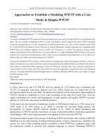
FIGURE 1.1: An image of the AIBO and the field. The robot has a field-of-view of 56.9◦ (hor) and
45.2◦ (ver), by which it can use the two goals and four visually distinct beacons at the field corners for
the purposes of localization.
the best human soccer team on a real soccer field [42]. RoboCup is organized into several
different leagues, including a computer simulation league and two leagues that use wheeled
robots. The case study presented in this lecture concerns the development of a new team for
the Sony four-legged league1 in which all competitors use identical Sony AIBO robots and
the Open-R software development kit.2 Here, teams of four AIBOs, equipped with visionbased sensors, play soccer on a color-coded field. Figure 1.1 shows one of the robots along
with an overhead view of the playing field. As seen in the diagram, there are two goals, one
at each end of the field and there is a set of visually distinct beacons (markers) situated at
fixed locations around the field. These objects serve as the robot’s primary visual landmarks for
localization.
The Sony AIBO robot used by all the teams is roughly 280 mm tall (head to toe) and
320 mm long (nose to tail). It has 20 degrees of freedom: 3 in its head, 3 in each leg, and 5
more in its mouth, ears, and tail. It is equipped with a CMOS color camera at the tip of its
nose with a horizontal field-of-view of 56.9◦ and a vertical field-of-view of 45.2◦ . Images are
captured at 30 frames per second in the YCbCr image format. The robot also has a wireless
1
2
/> />
robotics
Mobk082
July 9, 2007
5:34
INTRODUCTION
LAN card that allows for communication with other robots or an off-board computer. All
processing is performed on-board the robot, using a 576 MHz processor.3 Since all teams use
identical robots, the four-legged league amounts to essentially a software competition.
This lecture details both the development process and the technical details of its end
result, a new RoboCup team, called UT Austin Villa,4 from the Department of Computer
Sciences at The University of Texas at Austin. The main contributions are
1. A roadmap for new classes and research groups interested in intelligent autonomous
robotics who are starting from scratch with a new robot; and
2. Documentation of the algorithms behind our own approach on the AIBOs with the
goal of making them accessible for use on other vision-based and/or legged robot
platforms.
As a case study, this lecture contains significant material that is motivated by the specific
robot soccer task. However, the main general feature of the class and research program described
is that there was a concrete task-oriented goal with a deadline. Potential tasks other than soccer
include autonomous surveillance [1, 56], autonomous driving [50], search and rescue [51], and
anything else that requires most of the same subtask capabilities as robot soccer as described in
Chapter 2.
Though development on the AIBOs has continued in our group for several years after the
initial ramp-up, this lecture focuses extensively on the first year’s work as an example of starting
up education and research on a new robot from scratch. Some of the later years’ developments
are also documented as useful and appropriate.
In the four-legged league, as in all RoboCup leagues, the rules are changed over time
to make the task incrementally more difficult. For example, in the first year of competition
documented in this lecture (2003), the field was 2.9 m × 4.4 m and there were walls surrounding
the field. By 2005, the field had been enlarged to 3.6 m × 5.4 m and the walls were removed.
As such, some of the images and anecdotes in this lecture reflect slightly different scenarios.
Nonetheless, the basic flow of games has remained unchanged and can be summarized as
follows.
3
r
Teams consist of four robots each;
r
Games consist of two 10-minute halves with teams switching sides and uniform colors
at half-time;
These specifications describe the most recent ERS-7 model. Some of the details described in this lecture pertain to
the early ERS-210A that was slightly smaller, had slightly less image resolution, and a somewhat slower processor.
Nonetheless, from a high level, most of the features of these two models are similar.
4
/>
3
robotics
Mobk082
4
July 9, 2007
5:34
INTELLIGENT AUTONOMOUS ROBOTICS
r
Once the play has started, the robots must operate fully autonomously, with no human
input or offboard computation;
r
The robots may communicate via a wireless LAN;
r
If the ball goes out of bounds, a human referee returns it to the field;
r
No defenders (other than the goalie) are allowed within the goalie box near the goal;
r
Robots may not run into other robots repeatedly;
r
Robots may not grasp the ball for longer than 3 s;
r
Robots that violate the rules are penalized by being removed from the field for 30 s,
after which they are replaced near the middle of the field;
r
At the end of the game, the team that has scored the most goals, wins.
Since some of these rules rely on human interpretation, there have been occasional
arguments about whether a robot should be penalized (sometimes hinging around what the
robot “intended” (!) to do). But, for the most part, they have been effectively enforced and
adhered to in a sportsmanlike way. Full rules for each year are available online at the fourlegged-league page cited above.
The following chapter outlines the structure of the graduate research seminar that was
offered as a class during the Spring semester of 2003 and that jump-started our project. At the
end of that chapter, I outline the structure of the remainder of the lecture.
robotics
Mobk082
July 9, 2007
5:34
5
CHAPTER 2
The Class
The UT Austin Villa legged robot team began as a focused class effort during the Spring
semester of 2003 at The University of Texas at Austin. Nineteen graduate students, and one
undergraduate student, were enrolled in the course CS395T: Multi-Robot Systems: Robotic Soccer
with Legged Robots.1
At the beginning of the class, neither the students nor the professor (myself) had any
detailed knowledge of the Sony AIBO robot. Students in the class studied past approaches
to four-legged robot soccer, both as described in the literature and as reflected in publicly
available source code. However, we developed the entire code base from scratch with the goals
of learning about all aspects of robot control and of introducing a completely new code base to
the community.
Class sessions were devoted to students educating each other about their findings and
progress, as well as coordinating the integration of everybody’s code. Just nine weeks after their
initial introduction to the robots, the students already had preliminary working solutions to
vision, localization, fast walking, kicking, and communication.
The concrete goal of the course was to have a completely new working solution by the
end of April so that we could participate in the RoboCup American Open competition, which
happened to fall during the last week of the class. After that point, a subset of the students
continued working towards RoboCup 2003 in Padova.
The class was organized into three phases. Initially, the students created simple behaviors
with the sole aim of becoming familiar with Open-R.
Then, about two weeks into the class, we shifted to phase two by identifying key subtasks
that were important for creating a complete team. Those subtasks were
1
r
Vision;
r
Movement;
r
Fall Detection;
r
Kicking;
/>
robotics
Mobk082
6
July 9, 2007
5:34
INTELLIGENT AUTONOMOUS ROBOTICS
r
Localization;
r
Communication;
r
General Architecture; and
r
Coordination.
During this phase, students chose one or more of these subtasks and worked in subgroups
on generating initial solutions to these tasks in isolation.
By about the middle of March, we were ready to switch to phase three, during which
we emphasized “closing the loop,” or creating a single unified code-base that was capable of
playing a full game of soccer. We completed this integration process in time to enter a team in
the RoboCup American Open competition at the end of April.
The remainder of the lecture is organized as follows. Chapter 3 documents some of the
initial behaviors that were generated during phase one of the class. Next, the output of some of
the subgroups that were formed in phase two of the class, is documented in Chapters 4–8. Next,
the tasks that occupied phase three of the class are documented, namely those that allowed us to
put together the above modules into a cohesive code base (Chapters 9–13). Chapters 14 and 15
introduce our simulator and debugging and development tools, and Chapter 16 concludes.
In all chapters, emphasis is placed on the general lessons learned, with some of the more
AIBO-specific details left for the appendices.
robotics
Mobk082
July 9, 2007
5:34
7
CHAPTER 3
Initial Behaviors
The first task for the students in the class was to learn enough about the AIBO, to be able to
compile and run any simple program on the AIBO.
The open source release of Open-R came with several sample programs that could
be compiled and loaded onto the AIBO right away. These programs could do simple tasks
such as the following.
L-Master-R-Slave: Cause the right legs to mirror manual movements of the left legs.
Ball-Tracking-Head: Cause the head to turn such that the pink ball is always in the center of
the visual image (if possible).
PID control: Move a joint to a position specified by the user by typing in a telnet window.
The students were to pick any program and modify it, or combine two programs in any
way. The main objective was to make sure that everyone was familiar with the process for
compiling and running programs on the AIBOs. Some of the resulting programs included the
following.
r
Variations on L-Master-R-Slave in which different joints were used to control each
other. For example, one student used the tail as the master to control all four legs,
which resulted in a swimming-type motion. Doing so required scaling the range of the
tail joints to those of the leg joints appropriately.
r
Variations on Ball-Tracking-Head in which a different color was tracked. Two students
teamed up to cause the robot to play different sounds when it found or lost the
ball.
r
Variations on PIDcontrol such that more than one joint could be controlled by the
same input string.
After becoming familiar with the compiling and uploading process, the next task for
the students was to become more familiar with the AIBO’s operating system and the OpenR interface. To that end, they were required to create a program that added at least one new
robotics
Mobk082
8
July 9, 2007
5:34
INTELLIGENT AUTONOMOUS ROBOTICS
subject–observer connection to the code.1 The students were encouraged to create a new OpenR object from scratch. Pattern-matching from the sample code was encouraged, but creating
an object as different as possible from the sample code was preferred.
Some of the responses to this assignment included the following.
r
The ability to turn on and off LEDs by pressing one of the robots’ sensors.
r
A primitive walking program that walks forward when it sees the ball.
r
A program that alternates blinking the LEDs and flapping the ears.
After this assignment, which was due after just the second week of the class, the students
were familiar enough with the robots and the coding environment to move on to their more
directed tasks with the aim of creating useful functionality.
1
A subject–observer connection is a pipe by which different Open-R objects can communicate and be made
interdependent. For example, one Open-R object could send a message to a second object whenever the back
sensor is pressed, causing the second object to, for example, suspend its current task or change to a new mode of
operation.
robotics
Mobk082
July 9, 2007
5:34
9
CHAPTER 4
Vision
The ability of a robot to sense its environment is a prerequisite for any decision making. Robots
have traditionally used mainly range sensors such as sonars and laser range finders. However,
camera and processing technology has recently advanced to the point where modern robots
are increasingly equipped with vision-based sensors. Indeed on the AIBO, the camera is the
main source of sensory information, and as such, we placed a strong emphasis on the vision
component of our team.
Since computer vision is a current area of active research, there is not yet any perfect
solution. As such, our vision module has undergone continual development over the course
of this multi-year project. This lecture focusses on the progress made during our first year
as an example of what can be done relatively quickly. During that time, the vision reached a
sufficient level to support all of the localization and behavior achievements described in the rest
of this lecture. Our progress since the first year is detailed in our 2004 and 2005 team technical
reports [79, 80], as well as a series of research papers [71–73, 76].
Our vision module processes the images taken by the CMOS camera located on the
AIBO. The module identifies colors in order to recognize objects, which are then used to
localize the robot and to plan its operation.
Our visual processing is done using the established procedure of color segmentation
followed by object recognition. Color segmentation is the process of classifying each pixel in an
input image as belonging to one of a number of predefined color classes based on the knowledge
of the ground truth on a few training images. Though the fundamental methods employed in
this module have been applied previously (both in RoboCup and in other domains), it has been
built from scratch like all the other modules in our team. Hence, the implementation details
provided are our own solutions to the problems we faced along the way. We have drawn some
of the ideas from the previous technical reports of CMU [89] and UNSW [9]. This module
can be broadly divided into two stages: (i) low-level vision, where the color segmentation and
region building operations are performed and (ii) high-level vision, wherein object recognition
is accomplished and the position and bearing of the various objects in the visual field are
determined.
robotics
Mobk082
10
July 9, 2007
5:34
INTELLIGENT AUTONOMOUS ROBOTICS
The problem dealt with in this chapter differs from more traditional computer vision
research in two important ways.
r
First, most state-of-the-art approaches to challenging computer vision problems, such
as segmentation [14, 55, 69, 85], blob clustering [28, 36], object recognition [5, 68, 88],
and illumination invariance [24, 25, 65] require a substantial amount of computational
and/or memory resources, taking advantage of multiple processors and/or processing
each image for seconds or even minutes. However, robotic systems typically have strict
constraints on the resources available, but still demand real-time processing. Indeed,
in order to take advantage of all the images available to it, we must enable the AIBO
to process each one in roughly 33 ms on its single 576 MHz processor.
r
Second, most vision algorithms assume a stationary or slowly (infrequently) moving
camera [22, 88]. However, mobile robot platforms such as ours are characterized by
rapid movements resulting in jerky nonlinear motion of the camera. These are the more
pronounced in legged robots as opposed to wheeled robots.
The remainder of this chapter presents detailed descriptions of the subprocesses of our
overall vision system. But first, for the sake of completeness, a brief overview of the AIBO
robot’s CMOS color camera is presented. The reader who is not interested in details of the
AIBO robot can safely skip to Section 4.2.
4.1
CAMERA SETTINGS
The AIBO comes equipped with a CMOS color camera that operates at a frame rate of 30 fps.
Some of its other preset features are as follows.
r
Horizontal viewing angle: 57.6◦ .
r
Vertical viewing angle: 47.8◦ .
r
Lens aperture: 2.0.
r
Focal length: 2.18 mm.
We have partial control over three parameters, each of which has three options from
which to choose:
r
White balance : We are provided with settings corresponding to three different light
temperatures.
1. Indoor-mode : 2800 K.
2. FL-mode : 4300 K.
3. Outdoor-mode : 7000 K.
robotics
Mobk082
July 9, 2007
5:34
VISION
11
This setting, as the name suggests, is basically a color correction system to accommodate
varying lighting conditions. The idea is that the camera needs to identify the ‘white point’ (such
that white objects appear white) so that the other colors are mapped properly. We found that
this setting does help in increasing the separation between colors and hence helps in better
object recognition. The optimum setting depends on the “light temperature” registered on
the field (this in turn depends on the type of light used, i.e., incandescent, fluorescent, etc.).
For example, in our lab setting, we noticed a better separation between orange and yellow
with the Indoor setting than with the other settings. This helped us in distinguishing the
orange ball from the other yellow objects on the field such as the goal and sections of the
beacons.
r
Shutter Speed:
1. Slow: 1/50 s.
2. Mid: 1/100 s.
3. Fast: 1/200 s.
This setting denotes the time for which the shutter of the camera allows light to enter the
camera. The higher settings (larger denominators) are better when we want to freeze the action
in an image. We noticed that both the ‘Mid’ and the ‘Fast’ settings did reasonably well though
the ‘Fast’ setting seemed the best, especially considering that we want to capture the motion of
the ball. Here, the lower settings would result in blurred images.
r
Gain:
1. Low: 0 dB.
2. Mid: 0 dB .
3. High: 6 dB.
This parameter sets the camera gain. In this case, we did not notice any major difference in
performance among the three settings provided.
4.2
COLOR SEGMENTATION
The image captured by the robot’s camera, in the YCbCr format, is a set of numbers, ranging
from 0 to 255 along each dimension, representing luminance (Y) and chrominance (Cb, Cr).
To enable the robot to extract useful information from these images, the numbers have to be
suitably mapped into an appropriate color space. We retain the YCbCr format and “train” the
robot, using a Nearest Neighbor (NNr) scheme [9, 15], to recognize and distinguish between
robotics
Mobk082
12
July 9, 2007
5:34
INTELLIGENT AUTONOMOUS ROBOTICS
10 different colors, numbered as follows:
r
0 = pink;
r
1 = yellow;
r
2 = blue;
r
3 = orange;
r
4 = marker green;
r
5 = red;
r
6 = dark (robot) blue;
r
7 = white;
r
8 = field green; and
r
9 = black.
The motivation behind using the NNr approach is that the colors under consideration
overlap in the YCbCr space (some, such as orange and yellow, do so by a significant amount).
Unlike other common methods that try to divide the color space into cuboidal regions (or a
collection of planes), the NNr scheme allows us to learn a color table where the individual blobs
are defined more precisely.
The original color space has three dimensions, corresponding to the Y, Cb, and Cr
channels of the input image. To build the color table (used for classification of the subsequent
images on the robot), we maintain three different types of color cubes in the training phase:
one Intermediate (IM) color cube corresponding to each color, a Nearest Neighbor cube, and
a Master (M) cube (the names will make more sense after the description given below). To
reduce storage requirements, we operate at half the resolution, i.e., all the cubes have their
numerical values scaled to range from 0 to 127 along each dimension. The cells of the IM cubes
are all initialized to zero, while those of the NNr cube and the M cube are initialized to nine
(the color black, also representing background).
Color segmentation begins by first training on a set of images using UT Assist, our
Java-based interface/debugging tool (for more details, see Chapter 15). A robot is placed at a
few points on the field. Images are captured and then transmitted over the wireless network
to a remote computer running the Java-based server application. The objects of interest (goals,
beacons, robots, ball, etc.) in the images are manually “labeled” as belonging to one of the
color classes previously defined, using the Image Segmenter (see Chapter 15 for some pictures
showing the labeling process). For each pixel of the image that we label, the cell determined by
the corresponding YCbCr values (after transforming to half-resolution), in the corresponding
IM cube, is incremented by 3 and all cells a certain Manhattan distance away (within 2 units)
robotics
Mobk082
July 9, 2007
5:34
VISION
13
Y
0
Cb
0
0
0
0
0
0
1
0
0
0
0
0
0
0
0
0
1
1
1
0
0
0
0
0
1
1
3
1
1
0
0
0
0
0
0
1
1
1
0
0
0
0
0
0
0
0
1
0
0
Cr
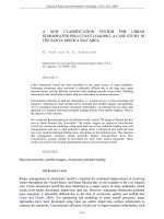
FIGURE 4.1: An example of the development of the color table, specifically the IM cube. Part (a)
shows the general coordinate frame for the color cubes. Part (b) shows a planar subsection of one of the
IM cubes before labeling. Part (c) depicts the same subsection after the labeling of a pixel that maps to
the cell at the center of the subsection. Here only one plane is shown—the same operation occurs across
all planes passing through the cell under consideration such that all cells a certain Manhattan distance
away from this cell are incremented by 1.
from this cell are incremented by 1. For example, if we label a pixel on the ball orange in the
image and this pixel corresponds to a cell (115, 35, 60) based on the intensity values of that
pixel in the image, then in the orange IM cube this cell is incremented by 3 while the cells such
as (115, 36, 61) and (114, 34, 60) (among others) which are within a Manhattan distance of
2 units from this cell, in the orange IM cube alone, are incremented by 1. For another example,
see Fig. 4.1.
The training process is performed incrementally, so at any stage we can generate a single
cube (the NNr cube is used for this purpose) that can be used for segmenting the subsequent
images. This helps us to see how “well-trained” the system is for each of the colors and serves as a
feedback mechanism that lets us decide which colors need to be trained further. To generate the
NNr cube, we traverse each cell in the NNr cube and compare the values in the corresponding
cell in each of the IM cubes and assign to this cell the index of the IM cube that has the
maximum value in this cell, i.e., ∀( p, q , r ) ∈ [0, 127],
NNrCube(y p , c b q , c r r ) = argmax IMi (y p , c b q , c r r ).
(4.1)
i∈[0,9]
When we use this color cube to segment subsequent images, we use the NNr scheme.
For each pixel in the test image, the YCbCr values (transformed to half-resolution) are used
to index into this NNr cube. Then we compute the weighted average of the value of this cell
and those cells that are a certain Manhattan distance (we use 2–3 units) around it to arrive at
a value that is set as the “numerical color” (i.e. the color class) of this pixel in the test image.
The weights are proportional to the Manhattan distance from the central cell, i.e., the greater
robotics
Mobk082
14
July 9, 2007
5:34
INTELLIGENT AUTONOMOUS ROBOTICS
9
3
1
1
9
9
3
1
1
9
3
1
3
3
3
3
1
3
3
3
3
3
1
3
3
3
3
3
3
3
1
1
3
3
3
1
1
3
3
3
9
1
3
3
9
9
1
3
3
9
(a)
(b)
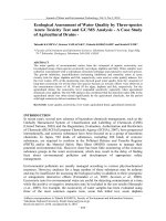
FIGURE 4.2: An example of the weighted average applied to the NNr cube (a two-dimensional
representative example). Part (a) shows the values along a plane of the NNr cube before the NNr scheme
is applied to the central cell. Part (b) shows the same plane after the NNr update for its central cell.
We are considering cells within a Manhattan distance of 2 units along the plane. For this central cell,
color label 1 gets a vote of 3 + 1 + 1 + 1 = 6 while label 3 gets a vote of 2 + 2 + 2 + 2 + 1 + 1 + 1 +
1 + 1 = 13 which makes the central cell’s label = 3. This is the value that is set as the classification
result. This is also the value that is stored in the cell in the M cube that corresponds to the central
cell.
this distance, the smaller the significance attached to the value in the corresponding cell (see
Fig. 4.2).
We do the training over several images (around 20–30) by placing the robot at suitable
points on the field. The idea here is to train on images that capture the beacons, goals, ball,
and the robots from different distances (and also different angles for the ball) to account for
the variations in lighting along different points on the field. This is especially important for the
orange ball, whose color could vary from orange to yellow to brownish-red depending on the
amount of lighting available at that point. We also train with several different balls to account for
the fact that there is a marked variation in color among different balls. At the end of the training
process, we have all the IM cubes with the corresponding cells suitably incremented. The NNr
operation is computationally intensive to perform on the robot’s processor. To overcome this,
we precompute the result of performing this operation (the Master Cube is used for this) from
the corresponding cells in the NNr color Cube, i.e., we traverse each cell of the M Cube and
compute the “Nearest Neighbor” value from the corresponding cells in the NNr cube. In other
words, ∀( p, q , r ) ∈ [0, 127] with a predefined Manhattan distance ManDist ∈ [3, 7],
MCube (y p , c b q , c r r ) = argmax Score(i)
i∈[0,9]
(4.2)
robotics
Mobk082
July 9, 2007
5:34
VISION
where ∀(k 1 , k2 , k3 ) ∈ [0, 127],
Score(i) =
15
ManDist − (| k 1 − p | + | k 2 − q | + | k 3 − r |) |
k1 ,k2 ,k3
(| k1 − p | + | k 2 − q | + | k 3 − r |) < ManDist
∧ NNrCube (yk1 , c b k2 , c r k3 ) = i.
(4.3)
This cube is loaded onto the robot’s memory stick. The pixel-level segmentation process
is reduced to that of a table lookup and takes ≈ 0.120 ms per image. For an example of the
color segmentation process and the Master Cube generated at the end of it, see Fig. 15.3.
One important point about our initial color segmentation scheme is that we do not make
an effort to normalize the cubes based on the number of pixels (of each color) that we train on.
So, if we labeled a number of yellow pixels and a relatively smaller number of orange pixels,
then we would be biased towards yellow in the NNr cube. This is not a problem if we are
careful during the training process and label regions such that all colors get (roughly) equal
representation.
Previous research in the field of segmentation has produced several good algorithms, for
example, mean-shift [14] and gradient-descent based cost-function minimization [85]. But
these involve more computation than is feasible to perform on the robots. A variety of previous
approaches have been implemented on the AIBOs in the RoboCup domain, including the use
of decision trees [8] and the creation of axis-parallel rectangles in the color space [12]. Our
approach is motivated by the desire to create fully general mappings for each YCbCr value [21].
4.3
REGION BUILDING AND MERGING
The next step in vision processing is to find contiguous blobs of constant colors, i.e., we need
to cluster pixels of the same color into meaningful groups. Though past research in this area
has resulted in some good methods [28, 36], doing this efficiently and accurately is challenging
since the reasoning is still at the pixel level. Computationally, this process is the most expensive
component of the vision module that the robot executes.
The Master cube is loaded onto the robot’s memory stick and this is used to segment the
images that the robot’s camera captures (in real-time). The next step in low-level processing
involves the formation of rectangular bounding boxes around connected regions of the same
color. This in turn consists of run-length encoding (RLE) and region merging [29, 58], which
are standard image processing approaches used previously in the RoboCup domain [89].
As each image is segmented (during the first scan of the image), left to right and top to
bottom, it is encoded in the form of run-lengths along each horizontal scan line, i.e., along each
line, we store the (x, y) position (the root node) where a sequence of a particular color starts