Electricity experiments you can do at home
Bạn đang xem bản rút gọn của tài liệu. Xem và tải ngay bản đầy đủ của tài liệu tại đây (5.95 MB, 352 trang )
Electricity
Experiments
You Can Do at Home
About the Author
Stan Gibilisco is an electronics engineer, researcher, and mathematician who has
authored Teach Yourself Electricity and Electronics, Electricity Demystified, more
than 30 other books, and dozens of magazine articles. His work has been published
in several languages.
Electricity
Experiments
You Can Do at Home
Stan Gibilisco
New York Chicago San Francisco Lisbon London Madrid
Mexico City Milan New Delhi San Juan Seoul
Singapore Sydney Toronto
Copyright © 2010 by The McGraw-Hill Companies, Inc. All rights reserved. Except as permitted under the United States
Copyright Act of 1976, no part of this publication may be reproduced or distributed in any form or by any means, or stored
in a database or retrieval system, without the prior written permission of the publisher.
ISBN: 978-0-07-162163-2
MHID: 0-07-162163-6
The material in this eBook also appears in the print version of this title: ISBN: 978-0-07-162164-9,
MHID: 0-07-162164-4.
All trademarks are trademarks of their respective owners. Rather than put a trademark symbol after every occurrence of a
trademarked name, we use names in an editorial fashion only, and to the benefit of the trademark owner, with no intention
of infringement of the trademark. Where such designations appear in this book, they have been printed with initial caps.
McGraw-Hill eBooks are available at special quantity discounts to use as premiums and sales promotions, or for use in
corporate training programs. To contact a representative please e-mail us at
Information contained in this work has been obtained by The McGraw-Hill Companies, Inc. (“McGraw-Hill”) from sources believed to be reliable. However, neither McGraw-Hill nor its authors guarantee the accuracy or completeness of any
information published herein, and neither McGraw- Hill nor its authors shall be responsible for any errors, omissions, or
damages arising out of use of this information. This work is published with the understanding that McGraw-Hill and its authors are supplying information but are not attempting to render engineering or other professional services. If such services
are required, the assistance of an appropriate professional should be sought.
TERMS OF USE
This is a copyrighted work and The McGraw-Hill Companies, Inc. (“McGrawHill”) and its licensors reserve all rights in
and to the work. Use of this work is subject to these terms. Except as permitted under the Copyright Act of 1976 and the
right to store and retrieve one copy of the work, you may not decompile, disassemble, reverse engineer, reproduce, modify,
create derivative works based upon, transmit, distribute, disseminate, sell, publish or sublicense the work or any part of it
without McGraw-Hill’s prior consent. You may use the work for your own noncommercial and personal use; any other use
of the work is strictly prohibited. Your right to use the work may be terminated if you fail to comply with these terms.
THE WORK IS PROVIDED “AS IS.” McGRAW-HILL AND ITS LICENSORS MAKE NO GUARANTEES OR WARRANTIES AS TO THE ACCURACY, ADEQUACY OR COMPLETENESS OF OR RESULTS TO BE OBTAINED
FROM USING THE WORK, INCLUDING ANY INFORMATION THAT CAN BE ACCESSED THROUGH THE
WORK VIA HYPERLINK OR OTHERWISE, AND EXPRESSLY DISCLAIM ANY WARRANTY, EXPRESS OR IMPLIED, INCLUDING BUT NOT LIMITED TO IMPLIED WARRANTIES OF MERCHANTABILITY OR FITNESS
FOR A PARTICULAR PURPOSE. McGraw-Hill and its licensors do not warrant or guarantee that the functions contained
in the work will meet your requirements or that its operation will be uninterrupted or error free. Neither McGraw-Hill nor
its licensors shall be liable to you or anyone else for any inaccuracy, error or omission, regardless of cause, in the work
or for any damages resulting therefrom. McGraw-Hill has no responsibility for the content of any information accessed
through the work. Under no circumstances shall McGraw-Hill and/or its licensors be liable for any indirect, incidental,
special, punitive, consequential or similar damages that result from the use of or inability to use the work, even if any of
them has been advised of the possibility of such damages. This limitation of liability shall apply to any claim or cause
whatsoever whether such claim or cause arises in contract, tort or otherwise.
To my physics advisor
at the University of Minnesota
circa 1974
who said:
One experimentalist can keep a dozen theorists busy.
This page intentionally left blank
Contents
Preface
xi
Part 1 Direct Current
1
DC1
DC2
DC3
DC4
DC5
DC6
DC7
DC8
DC9
DC10
DC11
DC12
DC13
DC14
DC15
DC16
DC17
DC18
DC19
DC20
DC21
DC22
DC23
Your Direct-Current Lab
Voltage Sources in Series
Current Sources in Series
A Simple Wet Cell
How “Electric” Are You?
Your Body Resistance
Resistances of Liquids
Ohm’s Law
Resistors in Series
Resistors in Parallel
Resistors in Series-Parallel
Kirchhoff’s Current Law
Kirchhoff’s Voltage Law
A Resistive Voltage Divider
A Diode-Based Voltage Reducer
Power as Volt-Amperes
Resistance as Volts per Ampere
“Identical” Lamps in Series
Dissimilar Lamps in Series
“Identical” Lamps in Parallel
Dissimilar Lamps in Parallel
A Compass-Based Galvanometer
Solar Module in Dim Light
vii
3
9
15
21
27
31
35
43
51
57
63
71
77
81
89
95
99
103
109
115
121
127
133
viii
Contents
DC24 Solar Module in Direct Sunlight
DC25 A Photovoltaic Illuminometer
139
145
Part 2 Alternating Current
AC1 Your Alternating-Current Lab
AC2 “Identical” Utility Bulbs in Series
AC3 Dissimilar Utility Bulbs in Series
AC4 A Simple Utility Bulb Saver
AC5 Galvanometer with AC
AC6 Galvanometer with Rectified AC
AC7 Ohm’s Law with Rectified AC
AC8 A Simple Ripple Filter
AC9 Rectifier and Battery
AC10 Rectifier/Filter and Battery
AC11 Rectifier and Battery under Load
AC12 Rectifier/Filter and Battery under Load
AC13 A Full-Wave Bridge Rectifier
AC14 A Filtered Full-Wave Power Supply
AC15 How Bleeders Work
AC16 A Zener-Diode Voltage Regulator
AC17 A Zener-Diode Voltage Reducer
AC18 An AC Spectrum Monitor
149
151
153
159
165
171
177
181
189
195
201
207
213
219
225
231
237
241
247
Part 3 Magnetism
MAG1 Your Magnetism Lab
MAG2 Test Metals for Ferromagnetism
MAG3 Compass Deflection versus Distance
MAG4 Magnetic Forces through Barriers
MAG5 Magnetic Declination
MAG6 “Magnetize” a Copper Wire
MAG7 Ampere’s Law with Straight Wire
MAG8 Ampere’s Law with Wire Loop
MAG9 Build a DC Electromagnet
MAG10 DC Electromagnet near Permanent Magnet
MAG11 DC Electromagnets near Each Other
MAG12 Build an AC Electromagnet
253
255
257
261
267
271
275
279
285
291
297
301
305
Contents
MAG13
MAG14
MAG15
MAG16
AC Electromagnet near Permanent Magnet
AC Electromagnet near DC Electromagnet
AC Electromagnets near Each Other
A Handheld Wind Turbine
Alternative Parts Suppliers
Suggested Additional Reading
Index
ix
309
315
319
325
331
333
335
This page intentionally left blank
Preface
This book will educate you, give you ideas, and provoke your curiosity. The
experiments described here can serve as a “hands-on” supplement for any basic
text on electricity. I designed these experiments for serious students and hobbyists.
If you don’t have any prior experience with electrical circuits or components, I
recommend that you read Electricity Demystified before you start here. If you
want a deeper theoretical treatment of the subject, you can also read Teach Yourself
Electricity and Electronics.
If you like to seek out mysteries in everyday things, then you’ll have fun with the
experiments described in this book. Pure theory might seem tame, but the real world
is wild! Some of these experiments will work out differently than you expect. Some,
if not most, of your results will differ from mine. In a few scenarios, the results will
likely surprise you as they surprised me. In a couple of cases, I could not at the time—
and still cannot—explain why certain phenomena occurred.
As I compiled this book, I tried to use inexpensive, easy-to-find parts. I visited the
local Radio Shack store many times, browsing their drawers full of components.
Radio Shack maintains a Web site from which you can order items that you don’t see
at their retail outlets. In the back of this book, you’ll find a list of alternative parts
suppliers. Amateur radio clubs periodically hold gatherings or host conventions at
which you can find exotic electrical and electronic components.
As you conduct the experiments described in this book, you’re bound to have
questions such as “Why are my results so vastly different from yours?” If this book
stirs up sufficient curiosity and enthusiasm, maybe I’ll set up a blog where we can
discuss these experiments (and other ideas, too). You can go to my Web site at
www.sciencewriter.net or enter my name as a phrase in your favorite search engine.
Have fun!
Stan Gibilisco
xi
This page intentionally left blank
Part 1
Direct Current
This page intentionally left blank
DC1
Your Direct-Current Lab
Every experimenter needs a good workbench. Mine is rather fancy: a piece of
plywood, weighted down over the keyboard of an old piano, and hung from the cellar
ceiling by brass-plated chains! Yours doesn’t have to be that exotic, and you can
put it anywhere as long as it won’t shake or collapse. The surface should consist
of a nonconducting material such as wood, protected by a plastic mat or a small
piece of closely cropped carpet (a doormat is ideal). A desk lamp, preferably the
“high-intensity” type with an adjustable arm, completes the arrangement.
Protect Your Eyes!
Buy a good pair of safety glasses at your local hardware store. Wear the glasses at
all times while doing any experiment described in this book. Get into the habit of
wearing the safety glasses whether you think you need them or not. You never
know when a little piece of wire will go flying when you snip it off with a diagonal cutters!
Table DC1-1 lists the items you’ll need for the experiments in this section.
Many of these components can be found at Radio Shack retail stores or ordered
through the Radio Shack Web site. A few of them are available at hardware stores,
department stores, and grocery stores. If you can’t get a particular component
from sources local to your area, you can get it (or its equivalent) from one of the
mail-order sources listed at the back of this book.
A Bed of Nails
For some of the experiments described in this section, you’ll need a prototypetesting circuit board called a breadboard. I patronized a local lumber yard to get
the wood for the breadboard. I found a length of “12-in by 3/4-in” pine in their
scrap heap. The actual width of a “12-in” board is about 10.8 in or 27.4 cm, and
the actual thickness is about 0.6 in or 15 mm. They didn’t charge me anything for
3
4 Part 1: Direct Current
Table DC1-1 Components list for DC experiments. You can find these items at retail stores
near most locations in the United States. Abbreviations: in ϭ inches, AWG ϭ American
wire gauge, V ϭ volts, tsp ϭ teaspoon, tbsp ϭ tablespoon, fl oz ϭ fluid ounces, W ϭ watts,
A ϭ amperes, K ϭ kilohms, and PIV ϭ peak inverse volts.
Quantity
1
1
1
12
100
1
1
1
1
1
1
1
1
1
1
2
1
6
2
1
1
1
1
2
1
1
1
1
1
1
1
1
1
1
1
Store Type or Radio
Shack Part Number
Lumber yard
Hardware store
Hardware store
Hardware store
Hardware store
Department store
Department store
or hardware store
Hardware store
Hardware store or
Radio Shack
Hardware store
Hardware store
Hardware store
278-1221
278-1345
Hardware store
278-1156
Hardware store
Hardware store
270-401A
270-391A
Grocery store
Grocery store
Hardware store
Hardware store
Grocery store
Grocery store
Grocery store
Grocery store
Grocery store
271-1111
271-1113
271-1115
271-1117
271-1118
271-1120
Description
Pine board, approx. 10.8 in ϫ 12.5 in ϫ 0.6 in
Pair of safety glasses
Small hammer
Flat-head wood screws, 6 ϫ 32 ϫ 3/4
Polished steel finishing nails, 11/4 in long
12-in plastic or wooden ruler
36-in wooden measuring stick (also called a
“yardstick”)
Tube of waterproof “airplane glue” or strong
contact cement
Digital multimeter, GB Instruments GDT-11 or
equivalent
Diagonal wire cutter/stripper
Small needle-nose pliers
Roll of AWG No. 24 solid bare copper wire
Three-roll package of AWG No. 22 hookup wire
Three-roll package of enamel-coated magnet wire
Small sheet of fine sandpaper
Packages of insulated test/jumper leads
Heavy-duty lantern battery rated at 6 V
Alkaine AA cells rated at 1.5 V
Holder for one size AA cell
Holder for four size AA cells in series
Pair of thick rubber gloves
Small pad of steel wool
Galvanized clamping strap, 5/8 in wide
Copper clamping strap, 1/2 in wide
Container of table salt (sodium chloride)
Container of baking soda (sodium bicarbonate)
Quart of white distilled vinegar
Set of measuring spoons from 1/4 tsp to 1 tbsp
Glass measuring cup that can hold 12 fl oz
Package of five resistors rated at 220 ohms and 1/2 W
Package of five resistors rated at 330 ohms and 1/2 W
Package of five resistors rated at 470 ohms and 1/2 W
Package of five resistors rated at 680 ohms and 1/2 W
Package of five resistors rated at 1 K and 1/2 W
Package of five resistors rated at 1.5 K and 1/2 W
DC1: Your Direct-Current Lab 5
Table DC1-1 Components list for DC experiments. You can find these items at retail stores
near most locations in the United States. Abbreviations: in ϭ inches, AWG ϭ American wire
gauge, V ϭ volts, tsp ϭ teaspoon, tbsp ϭ tablespoon, fl oz ϭ fluid ounces, W ϭ watts,
A ϭ amperes, K ϭ kilohms, and PIV ϭ peak inverse volts. (Continued)
Quantity
Store Type or Radio
Shack Part Number
1
1
271-1122
276-1104
1
Department store
1
2
1
Department store or
office supply store
272-357
272-1130
1
272-1133
1
277-1205
Description
Package of five resistors rated at 3.3 K and 1/2 W
Package of two rectifier diodes rated at 1 A and
600 PIV
Magnetic compass with degree scale,
WalMart FC455W or equivalent
Small hand-held paper punch that creates
1
/4-in holes
Miniature screw-base lamp holder
Package of two screw-base miniature lamps rated
at 6.3 V
Package of two screw-base miniature lamps rated
at 7.5 V
Encapsulated solar module rated at 6 V output in
bright sunlight
the wood itself, but they demanded a couple of dollars to make a clean cut so I
could have a fine rectangular piece of pine measuring 12.5 in (31.8 cm) long.
Using a ruler, divide the breadboard lengthwise at 1-in (25.4-mm) intervals,
centered so as to get 11 evenly spaced marks. Do the same going sideways to
obtain 9 marks at 1-in (25.4-mm) intervals. Using a ball-point or roller-point
pen, draw lines parallel to the edges of the board to obtain a grid pattern. Label
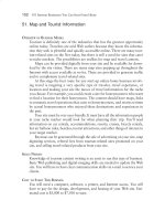
the grid lines from A to K and 1 to 9 as shown in Fig. DC1-1. That’ll give you
99 intersection points, each of which can be designated by a letter-number pair
such as D-3 or G-8.
Once you’ve marked the grid lines, gather together a bunch of 1.25-in (31.8-mm)
polished steel finishing nails. Place the board on a solid surface that can’t be
damaged by scratching or scraping. A concrete or asphalt driveway is ideal for this
purpose. Pound a nail into each grid intersection point as shown in Fig. DC1-1. Be
sure the nails are made of polished steel, preferably with “tiny heads.” The nails
must not be coated with paint, plastic, or any other insulating material. Each nail
should go into the board just far enough so that you can’t wiggle it around. I
pounded every nail down to a depth of approximately 0.3 in (8 mm), halfway
through the board.
6 Part 1: Direct Current
Lamp
holder
A
B
C
Lamp
holder
D
E
F
G
H
I
J
K
1
2
3
4
5
6
7
8
9
Holder for four
size AA cells
Holders for single
size AA cells
Figure DC1-1 Layout of the breadboard for DC experiments. I
used a “12-in” pine board (actually 10.8 in wide) with a thickness
“3/4 in” (actually about 0.6 in), cut to a length of 12.5 in. Solid dots
show the positions of the nails. Grid squares measure 1 in by 1 in.
Lamp and Cell Holders
Using 6 ϫ 32 flat-head wood screws, secure the two miniature lamp holders to the
board at the locations shown in Fig. DC1-1. Using short lengths of thin, solid, bare
copper wire, connect the terminals of one lamp holder to breadboard nails A-2 and
D-1. Connect the terminals of the other lamp holder to nails D-2 and G-1. Wrap
DC1: Your Direct-Current Lab 7
the wire tightly at least twice, but preferably four times, around each nail. Snip off
any excess wire that remains.
Glue two single-cell AA battery holders and one four-cell AA battery holder to
the breadboard with contact cement. Allow the cement to harden for 48 hours.
Then strip 1 in of the insulation from the ends of the cell-holder leads and connect
the leads to the nails as shown in Fig. DC1-1. Remember that the red leads are positive and the black leads are negative. Use the same wire-wrapping technique that
you used for the lamp-holder wires. Place fresh AA cells in the holders with the
negative sides against the springs. Your breadboard is now ready to use.
Wire Wrapping
The breadboard-based experiments in this book employ a construction method
called wire wrapping. Each of the nails in your breadboard forms a terminal to
which several component leads or wires can be attached. To make a connection,
wrap an uninsulated wire or lead around a nail in a tight, helical coil. Make at least
two, but preferably four or five, complete wire turns as shown in Fig. DC1-2.
Polished steel
finishing nail
Wire or
component
lead
Breadboard
Figure DC1-2 Wire-wrapping technique.
Wind the wire or component lead at least
twice, but preferably four or five times,
around the nail. Extra wire should be snipped
off if necessary, using a diagonal cutter.
8 Part 1: Direct Current
When you wrap the end of a length of wire, cut off the excess wire after wrapping. For small components such as resistors and diodes, wrap the leads around the
nails as many times as is necessary to use up the entire lead length. That way, you
won’t have to cut down the component leads. You’ll be able to easily unwrap and
reuse the components for later experiments. Needle-nose pliers can help you to
wrap wires or leads that you can’t wrap with your fingers alone.
When you want to make multiple connections to a single nail, you can wrap one
wire or lead over the other, but you shouldn’t have to do that unless you’ve run out
of nail space. Each nail should protrude approximately 1 in above the board surface, so you won’t be cramped for wrapping space. Again, let me emphasize that
the nails should be made of polished steel without any coating. They should be
new and clean, so they’ll function as efficient electrical terminals.
Let’s Get Started!
When you perform the experiments in this section, the exact arrangement of parts
on the breadboard is up to you. I’ve provided schematic and/or pictorial diagrams
to show you how the components are interconnected.
Small components such as resistors and diodes should be placed between adjacent
nails, so that you can wrap each lead securely around each nail. Jumper wires (also
known as clip leads) should be secured to the nails so that the “jaws” can’t easily
be pulled loose. It’s best to clamp jumpers to nails sideways, so that the wires come
off horizontally.
Caution! Use needle-nose pliers and rubber gloves for any wire-wrapping operations if the voltage at any exposed point might exceed 10 V.
Caution! Wear safety glasses at all times as you do these experiments, whether you
think you need the glasses or not.
DC2
Voltage Sources
in Series
In this experiment, you’ll find out what happens when you connect electrical cells
or batteries in series (that is, end-to-end) in the same direction. Then you’ll discover what occurs when you connect one of the cells in the wrong direction.
Finally, you’ll get a chance to do your own experiment and see if you can predict
what will take place.
What’s a Volt?
Current can flow through a device or system only if electrical charge carriers
(such as electrons) are “pushed” or “motivated.” The “motivation” can be provided
by a buildup of charge carriers, with positive polarity (a shortage of electrons) in
one place and negative polarity (an excess of electrons) in another place. In a situation like this, we say that an electromotive force (EMF) exists. This force is
commonly called voltage, and it’s expressed in units called volts (symbolized V).
You’ll occasionally hear voltage spoken of as electrical potential or potential
difference.
How large is a potential difference of 1 V? You can get an idea when you
realize that a flashlight cell produces about 1.5 V, a lantern battery about
6 V, an automotive battery 12 to 14 V, and a standard household utility outlet
110 to 120 V. Cells and batteries produce direct-current (DC) voltages, while
household utility systems in the United States produce alternating-current
(AC) voltages.
For the following set of experiments, you’ll need two size AA flashlight cells
rated at 1.5 V, one lantern battery rated at 6 V, and a digital meter capable of measuring low DC voltages, accurate to within 0.01 V.
9
10
Part 1: Direct Current
Cell and Battery Working Together
In an open circuit where series-connected cells or batteries aren’t hooked up to any
external device or system, the voltages always add up, as long as we connect the
cells in the same direction. This is true even if the individual cells are of different
electrochemical types, such as zinc-carbon, alkaline, or lithium-ion. For this rule
to hold, however, you must be sure that all the cells are connected plus-to-minus,
so that they work together. The rule does not apply if any of the cells is reversed
so that its voltage bucks (works against, rather than with) the voltages produced by
the other cells.
When I measured the voltages of the new AA cells I purchased for this experiment, each cell tested at 1.58 V. The lantern battery produced 6.50 V. Your cells
and battery will probably have different voltages than mine did, so be sure that you
test each cell or battery individually.
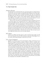
According to basic electricity theory, I expected to get 8.08 V when I connected
one AA cell in series with the lantern battery and then measured the voltage across
the whole combination. By simple addition,
1.58 V ϩ 6.50 V ϭ 8.08 V
There were two different ways to connect these two units in series. Figure DC2-1
shows the arrangements, along with the theoretical and measured voltages. These
wiring diagrams use the standard schematic symbols for a cell, a battery, and a
meter. The voltages I measured for the series combinations were both 10 millivolts (mV)
less than the theoretical predictions. A millivolt is equal to 0.001 V, so 10 mV is
0.01 V. That’s not enough error to be of any concern. Small discrepancies like this
are common in physical science experiments.
To build the battery-cell combination, I placed the battery terminal against the
cell terminal, holding the two units together while manipulating the meter probes.
I grasped the probes and the cell to keep the arrangement from falling apart. The
voltages in this experiment weren’t dangerous, but I wore rubber gloves (the sort
people use for washing dishes) to keep my body resistance from affecting the voltage readings.
Cell Conflicting with Battery
In the arrangement shown by Fig. DC2-1, we actually have five electrochemical
cells connected in series, because the lantern battery contains four internal cells. If
you reverse the polarity of the AA cell, you might be tempted to suppose that its
voltage will subtract from that of the battery, instead of adding to it. However, in
DC2: Voltage Sources in Series 11
Lantern
battery
–
+
AA cell
–
6.50 V
+
1.58 V
A
Voltmeter
Theory says 8.08 V
and
I measured 8.07 V
AA cell
–
+
1.58 V
Lantern
battery
–
+
6.50 V
B
Voltmeter
Theory says 8.08 V
and
I measured 8.07 V
Figure DC2-1 Here’s what happened when I
connected a lantern battery and a flashlight cell in
series so that they worked together. At A, the positive pole of the battery went to the negative pole of
the cell. At B, the positive pole of the cell went to
the negative pole of the battery.
12
Part 1: Direct Current
physical science, suppositions and assumptions often turn out to be wrong! Let’s
test such an arrangement and see what really occurs.
Figure DC2-2 shows two ways to connect the AA cell so that its voltage bucks
the battery voltage. Theory predicts 4.92 V across either of these series combinations, because
6.50 V Ϫ 1.58 V ϭ 4.92 V
Lantern
battery
–
+
AA cell
+
6.50 V
–
1.58 V
A
Voltmeter
Theory says 4.92 V
and
I measured 4.92 V
AA cell
–
+
1.58 V
Lantern
battery
–
+
6.50 V
B
Voltmeter
Theory says 4.92 V
and
I measured 4.92 V
Figure DC2-2 When I connected a lantern battery and flashlight cell in series so that they
worked against each other, the cell’s voltage took
away from the battery’s voltage. At A, plus-to-plus;
at B, minus-to-minus.