Hướng dẫn tính toán gia cường dầm BTCT bằng vật liệu Composite
Bạn đang xem bản rút gọn của tài liệu. Xem và tải ngay bản đầy đủ của tài liệu tại đây (3.71 MB, 78 trang )
This self-guided presentation covers the use of externally bonded FRP systems for strengthening
existing concrete structures. The content of the presentation follows the guidelines given in the
ACI 440.2R-08 document.
1
The presentation will now focus on the engineering principles involved in designing the layout
of an FRP strengthening system.
2
First this presentation will cover flexural strengthening.
3
The design procedures for flexural strengthening are covered in Chapter 10 of the ACI 440.2R
document. Some lab tests have shown increases in flexural capacity from FRP systems of up to
160%. However, when considering serviceability limits, safety factors, and practical issues, it is
more reasonable that increases up to 40% can be attained (note that the increases referred to are
increases in ultimate or design moment capacity). It is possible to increase both positive and
negative moment capacity and both reinforced and prestressed (or post-tensioned) concrete
members can be strengthened for flexure. Furthermore, it is generally recognized that FRP
reinforcement will improve flexural crack distribution and reduce crack widths, although
specific design guidelines for determining this reduction are not currently available in the ACI
440.2R document. The document also does not give specific guidelines on strengthening for
flexural loads due to seismic forces.
The objective for any flexural strengthening application is to provide a design moment capacity
greater than the moment demand. This is expressed as Eqn (10-1) and is similar to the general
requirements given in ACI 318.
4
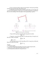
The general load-deflection behavior of FRP strengthened flexural members is shown here.
Note that increases in FRP reinforcement do result in additional flexural strength being attained.
However, increases in FRP reinforcement also result in reduced deformation capacity and
ductility. It is also important to note here that increases in FRP reinforcement do not necessarily
result in proportional increases in strength.
5
In order to compute the flexural strength of a member strengthened with FRP reinforcement, the
basic principles of reinforced concrete will be employed. As such, the assumptions shown are
made in developing the equations for ACI 440.2R. (Note that many of these assumptions are
similar to the assumptions used to develop ACI 318.)
6
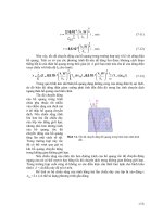
For purposes of illustrating the calculations required for determining the strengthening effect of
FRP flexural reinforcement, consider the regularly reinforced/FRP strengthened concrete beam
shown. The ultimate strength of the beam will be determined based on simultaneously
satisfying strain compatibility and internal force equilibrium. The flexural strength of the
section will be gained from the contribution of a compressive resultant force in the concrete, the
tensile force from the existing steel reinforcement, and the tensile force contribution from the
FRP system. This again is very similar to regular steel reinforced concrete design.
7
One of the primary design differences between regular steel reinforced concrete and FRP
strengthened concrete, is the number and type of failure modes that can occur. All of the failure
modes listed must be considered. It is important to note that both failure modes 1 and 4 are
brittle, sudden failure modes. It is most often advisable to avoid these failure modes. Failure
mode 4, cover delamination, is a unique failure mode and will be dealt with in more depth in the
design detailing portion of this presentation.
8
Like regular reinforced concrete, the flexural behavior of FRP strengthened concrete can be
elastic until yielding of the existing steel reinforcement followed by failure initiated by crushing
of the concrete in compression. Note that with this failure mode there is still significant
deformation (and therefore warning of failure). This is due to the existing steel reinforcement
undergoing significant deformation after yielding.
9
The flexural behavior of FRP strengthened concrete can also be steel yielding followed by
failure of the FRP. This can either be failure due to rupture of the FRP (the FRP reaching its
ultimate tensile strength) or by FRP debonding off of the surface of the concrete. Again
significant deformation is attained by significant post-yield elongation of the existing steel
reinforcement. (Also note with this failure mode that once the FRP fails, the beam does still
have some residual strength and deflection capacity based on the original unstrengthened
section.)
10
ACI 440.2R gives equations to determine the point at which the FRP material will debond from
the concrete. These equations, shown, yield a debonding strain value. This strain is a function
of the concrete strength and stiffness of the FRP reinforcement – higher stiffness materials
debonding at lower levels of stress than lower stiffness materials. (Also note that the variable
“n” is the number of layers of FRP reinforcement, and “tf” is the thickness of the FRP
reinforcement per layer.)
11
It is important to recognize that the full ultimate strength of the FRP will rarely be realized. If
FRP debonding controls failure, only the percentage of ultimate strength will be attained. If
concrete crushing controls failure, the concrete will reach its maximum compressive strain
before the FRP reaches its rupture strain. Thus, the concept of “effective strain” is introduced in
the ACI 440.2R guideline. The “effective strain” is the strain level achieved in the FRP when
the section fails (due to concrete crushing, FRP debonding, etc.). Note that since FRP materials
are 100% linearly elastic, the effective strain is linearly proportional to the stress developed in
the FRP material as well.
12
For this reason, the moment capacity cannot be calculated by simply “plugging in” the yield
strength of the steel, fy, as the stress in the steel and the ultimate strength of the FRP, ffu, as the
stress in the FRP. The stress, particularly in the FRP, must be determined through an iterative
process of simultaneously satisfying strain compatibility and force equilibrium.
13
The procedure for computing the stresses and ultimately arriving at the moment capacity is
performed by the steps shown.
14
The first step involves calculating the strain in the substrate at the time that the FRP is installed.
It is important to realize that the FRP is usually bonded to surfaces that are already stressed. For
example when bonding FRP to the bottom of a beam, the bottom of the beam may already be
under tension due to its self weight and dead loads. Since the FRP is installed unstressed, it is
not capable of resisting these loads that are already in place. For calculation purposes, the state
of strain on the substrate when the FRP is being installed should be calculated so that it can be
subtracted from the strain in the FRP at increasing levels of load. The initial substrate strain can
be computed from the equation shown where Mip is the bending moment in the section due to
the existing loads on the member.
15
The second step (and the first step in the iterative calculation procedure), is to estimate the
neutral axis depth at ultimate, c. The estimated neutral axis depth will be checked to see if it
satisfies both strain compatibility and internal force equilibrium. If these two conditions are not
satisfied, the neutral axis depth will need to be revised and checked again. It will first be
assumed that strain compatibility is satisfied. Force equilibrium may then be checked.
16
Given the neutral axis depth and assuming strain compatibility is satisfied, the strain in the FRP
can be determined by Eqn (10-3). This equation will also indicate which mode of failure will
govern.
17
With the strain in the FRP determined, the strain level in the steel reinforcement and concrete
can be determined.
18
With the strain level in each material, the stresses in each material can be determined as well.
For the steel reinforcement (which is idealized as elastic-perfectly plastic), Eqn 10-9 will
indicate the stress level in the steel. For the FRP (which is idealized as perfectly elastic), the
stress level can be determined from Eqn 10-4.
19
It should be recognized, that ACI 318 uses a stress block model for estimating the compressive
stress distribution in the concrete – the Whitney stress block. This model is only valid when
concrete crushing is governing failure. If FRP failure governs failure, the strain level in the
concrete may be substantially lower than 0.003-in/in. The Whitney stress block will not give an
equivalent stress distribution for this condition. The actual non-linear stress distribution in the
concrete must be considered or an alternative equivalent stress block model must be employed.
20
One equivalent stress block model, for concrete strains less than 0.003-in/in, is shown here.
21
With all of the material stresses determined, internal force equilibrium may be checked. If the
neutral axis depth, c, determined by the equation shown is different from the estimated neutral
axis depth, then force equilibrium is not satisfied. The neutral axis depth must then be revised
and the iterative process repeated until force equilibrium is satisfied.
22
With strain compatibility and force equilibrium satisfied, the nominal moment strength of the
reinforced/strengthened concrete section may be determined.
23
As mentioned before, it is possible to “over-reinforce” a section with FRP reinforcement and
cause a significant loss of flexural ductility in the concrete section. It is, therefore,
recommended to follow the procedure given in ACI 318 Appendix B to compensate for a loss of
ductility with a higher reserve of strength. If the strain in the steel is above 0.005-in/in at
failure, the section is viewed to be adequately ductile and a normal strength reduction factor of
0.90 can be used. If the steel does not yield, the section is viewed to be non-ductile and a
strength reduction factor of 0.70 should be used. A linear transition between reduction factors
should be used when the strain in the steel is between the strain at yield and 0.005-in/in.
24
With the strength reduction factor, phi, computed, the design moment strength may be
computed. Here we also introduce a “partial” reduction factor applied only to the FRP
contribution to the flexural strength. This partial reduction factor is used in recognition of the
fact that FRP reinforcement is not as statistically reliable as internal steel reinforcement. The
partial reduction factor for FRP flexural reinforcement is 0.85.
25