Networking and internetworking with microcontrollers by fred eady
Bạn đang xem bản rút gọn của tài liệu. Xem và tải ngay bản đầy đủ của tài liệu tại đây (30.94 MB, 370 trang )
Unauthorized reproduction or distribution of this eBook may result in severe
criminal penalties.
Unauthorized reproduction or distribution of this eBook may result in severe criminal penalties.
Networking and Internetworking
with Microcontrollers
By Fred Eady
AMSTERDAM • BOSTON • HEIDELBERG • LONDON
NEW YORK • OXFORD • PARIS • SAN DIEGO
SAN FRANCISCO • SINGAPORE • SYDNEY • TOKYO
Newnes is an imprint of Elsevier
Newnes is an imprint of Elsevier
200 Wheeler Road, Burlington, MA 01803, USA
Linacre House, Jordan Hill, Oxford OX2 8DP, UK
Copyright © 2004, Elsevier Inc. All rights reserved.
No part of this publication may be reproduced, stored in a retrieval system, or transmitted in
any form or by any means, electronic, mechanical, photocopying, recording, or otherwise,
without the prior written permission of the publisher.
Permissions may be sought directly from Elsevier’s Science & Technology Rights Department
in Oxford, UK: phone: (+44) 1865 843830, fax: (+44) 1865 853333, e-mail:
You may also complete your request on-line via the Elsevier
homepage (), by selecting “Customer Support” and then “Obtaining
Permissions.”
Recognizing the importance of preserving what has been written, Elsevier prints its books
on acid-free paper whenever possible.
Library of Congress Cataloging-in-Publication Data
(Application submitted.)
British Library Cataloguing-in-Publication Data
A catalogue record for this book is available from the British Library.
ISBN: 0-7506-7698-1
For information on all Newnes publications
visit our website at www.newnespress.com
03 04 05 06 07 08 10 9 8 7 6 5 4 3 2 1
Printed in the United States of America
Contents
Preface ................................................................................................................. ix
A Quick Look at the Microcontrollers .................................................................................. x
Atmel’s AVR ................................................................................................................. x
Microchip’s PIC ........................................................................................................... xii
What’s on the CD-ROM? .................................................................................. xvi
Chapter 1: The Essence of Microcontroller Networking—RS-232 ......................... 1
Some History ...................................................................................................................... 3
RS-232 Standard Operating Procedure ................................................................................ 5
RS-232 Voltage Conversion Considerations ......................................................................... 8
Chapter 2: Implementing RS-232 with a Microcontroller .................................... 11
Basic RS-232 Hardware .................................................................................................... 11
Building a Simple Microcontroller RS-232 Transceiver ........................................................ 14
RS-232 Interface Hardware ........................................................................................ 15
A Microcontroller DCE Device .................................................................................... 16
Microchip’s PICkit 1 FLASH Starter Kit ........................................................................ 16
Writing Some Simple RS-232 Firmware ...................................................................... 20
A Bit of RS-232 Transmit Code ................................................................................... 27
Some RS-232 Receive Code ....................................................................................... 32
Chapter 3: Writing RS-232 Microcontroller Routines in BASIC ............................ 37
BASIC RS-232 .................................................................................................................. 37
Chapter 4: Building Some RS-232 Communications Hardware ........................... 43
A Few More BASIC RS-232 Instructions ............................................................................ 43
v
Contents
Chapter 5: Using Microcontroller USARTs ............................................................. 47
Some Interrupt-Driven USART Code ................................................................................. 50
Applying What We Know about RS-232 to the Atmel AVR ............................................... 70
Coding the AVR RS-232 Routines ............................................................................... 73
Chapter 6: I2C…The Other Serial Protocol ............................................................. 81
Why use I²C? ................................................................................................................... 83
The I²C bus ...................................................................................................................... 83
I²C ACKS and NAKS .................................................................................................. 86
More on Arbitration and Clock Synchronization ......................................................... 87
I²C Addressing ........................................................................................................... 91
Some I²C Firmware .................................................................................................... 91
The AVR Master I²C Code .......................................................................................... 92
The AVR I²C Master-Receiver Mode Code .................................................................. 97
The PIC I²C Slave-Transmitter Mode Code .................................................................. 99
The AVR-to-PIC I²C Communications Ball ................................................................. 105
Chapter 7: Ethernet ............................................................................................... 121
What is Ethernet? .......................................................................................................... 121
The CS8900A-CQ .......................................................................................................... 122
CS8900A-CQ Reset Overview .................................................................................. 123
CS8900A-CQ Media Interface Overview .................................................................. 123
CS8900A-CQ Transmit Process Overview ................................................................. 123
CS8900A-CQ Receive Process Overview ................................................................... 124
CS8900A-CQ External Storage Overview ................................................................. 125
CS8900A-CQ Status Indicators ................................................................................. 126
The CS8900A-CQ MAC Engine ................................................................................ 126
Easy Ethernet CS8900A Hardware .................................................................................. 130
The PIC16F877 Microcontroller ................................................................................ 130
The Microchip PIC18F452 ........................................................................................ 131
The CS8900A-CQ Ethernet Engine ................................................................................. 131
Powering the CS8900A-CQ ............................................................................................ 132
The CS8900A-CQ Ethernet Magnetics ............................................................................ 132
Designing in the Easy Ethernet CS8900A’s PIC16F877 Microcontroller ............................. 135
The ICSP (In-Circuit Serial Programming) Interface .......................................................... 136
Developing the Easy Ethernet CS8900A Firmware .......................................................... 139
Setting up the PIC16F877 Microcontroller ....................................................................... 141
Carving up the PIC16F877’s Memory Resources .............................................................. 143
Function Prototypes ................................................................................................. 143
Defining the Variables .............................................................................................. 144
The Easy Ethernet CS8900A Macros ............................................................................... 151
Defining the CS8900A-CQ PacketPage Register Set ........................................................ 156
CS8900A-CQ Bus Interface Registers ....................................................................... 158
Product Identification Code ...................................................................................... 158
vi
Contents
CS8900A-CQ Status and Control Registers ............................................................... 159
Did It Register? ........................................................................................................ 172
Chapter 8: Writing the CS8900A-CQ Firmware .................................................. 173
The First Step ................................................................................................................. 174
Reset the CS8900A-CQ .................................................................................................. 175
Load the CS8900A-CQ Basic Parameters ........................................................................ 176
Load the CS8900A-CQ Individual Address Register Set ................................................... 178
Enable the CS8900A-CQ Transmitter and Receiver .......................................................... 179
The Main Service Loop ................................................................................................... 180
A Frame Under the Microscope ...................................................................................... 182
The Art of ARP ............................................................................................................... 189
Chapter 9: PINGing the Easy Ethernet CS8900A ................................................. 203
Chapter 10: UDP and the Easy Ethernet CS8900A .............................................. 221
A UDP Internet Test Panel ............................................................................................... 223
Chapter 11: TCP and the Easy Ethernet CS8900A............................................... 239
The Physical Layer .......................................................................................................... 241
The Data Link Layer ........................................................................................................ 241
The Network Layer ......................................................................................................... 242
The Transport Layer ........................................................................................................ 242
The Application Layer ..................................................................................................... 242
Coding TCP/IP for the Easy Ethernet CS8900A ............................................................... 244
Chapter 12: Let’s Do It Again ................................................................................ 293
Easy Ethernet Whacked??? What the…? ....................................................................... 293
The Realtek RTL8019AS ................................................................................................. 294
The Easy Ethernet W Hardware ...................................................................................... 302
The Easy Ethernet W Firmware ....................................................................................... 304
Initializing the Realtek RTL8019AS .................................................................................. 307
Online with the Easy Ethernet W .................................................................................... 324
Sending a Frame using the Easy Ethernet W ................................................................... 327
Tools for Work and Play .................................................................................................. 331
Chapter 13: Putting the Easy Ethernet AVR Online ........................................... 337
Chapter 14: Finale ................................................................................................. 347
Obtaining Easy Ethernet Devices ..................................................................................... 348
About the Author .................................................................................................. 349
Index ....................................................................................................................... 351
vii
Preface
There are lots of philosophical things I could say here. However, I don’t claim to be a philosopher or a poet. My days are spent designing microcontroller hardware, writing code to
drive that hardware and then writing about my adventures.
This book is a mean-business document designed to give you the knowledge needed to
network microcontroller-based devices successfully. Before you turn the last page of this
book, you’ll know how to integrate RS-232, I²C and Ethernet into a network device that can
be used to communicate via LAN, WAN or Internet. In addition to the knowledge you will
gain building the network devices, you’ll also walk away with in-depth knowledge of how the
code within those network devices works.
Our microcontroller-based network devices will be fabricated using microcontrollers from
Atmel and Microchip. To maintain consistency at the coding level, I’ll use ImageCraft’s
ICCAVR Pro C Compiler for the Atmel parts and Custom Computer Service’s CCS PIC C
Compiler for the PIC parts. Both of these C compilers are moderately priced and easily
obtainable via the Internet. You should be able to easily port the C source code from any
project in this book to other variants of C.
Our networking adventure will begin with RS-232. We’ll build on what we learn in the
RS-232 sections and ultimately implement both an I²C-bus and an Ethernet interface. No bit
will be left unturned. What you don’t see in the pages of this book can be found on the
companion CD-ROM. There’s also a support web site () where you can
get technical support and purchase parts, kits and assembled units that are discussed in this
book.
Both Atmel and Microchip provide a free IDE that you can get for a download from their
respective web sites. I’ll use Atmel’s AVR Studio and Microchip’s MPLAB exclusively when
working with these microcontrollers. To provide an extra layer of visibility into the
microcontrollers, I’ll employ the services of a Microchip MPLAB ICE 2000, a Microchip
MPLAB ICD 2 and an Atmel AVR JTAG ICE. On the networking side, I’ll use a Network
Associates Sniffer to show you what’s inside the Ethernet packets.
ix
Preface
OK…now that you know what this book is about, let’s go build some microcontrollerbased network devices.
A Quick Look at the Microcontrollers
Atmel’s AVR
The Atmel AVR is a very capable and highly networkable microcontroller. There are a
number of AVR families, which include the standard AVR line, a low-power AVR
microcontroller set, the tinyAVR family and the ATmega AVR microcontrollers. I’ve chosen
to concentrate on networking the ATmega AVR microcontrollers for a number of reasons.
Many of the legacy AVRs are being replaced by faster and more powerful ATmega AVRs. For
instance, the ATmega16 has replaced the ATmega163 and the ATmega32 has shoved the
ATmega323 out. In addition to added functionality, the AVR upgrades fix bugs found in the
older silicon they are replacing.
I’m not going to get into internal differences found in the AVR versus other
microcontrollers that could be called AVR peers. That’s what datasheets are for. However, I
will give you my reasons for employing the ATmega AVRs as microcontrollers in network
devices. The ATmega AVRs that I will network all have a maximum clock speed of 16 MHz.
That may not sound “fast,” but the ATmega AVRs execute most instructions in a single cycle
and thus are capable of producing 16 MIPS with a 16MHz clock. Basically, the number in
the name of a ATmega AVR represents the amount of program Flash in kilobytes. The
ATmega16 contains 16K of program Flash while an ATmega32 has 32K words of program
flash. The largest ATmega AVR, the ATmega128, contains 128K of program Flash memory.
The large portions of program memory are supplemented by big slices of SRAM. The
ATmega16 is loaded with 1K of SRAM and the ATmega32 SRAM area doubles the
ATmega16 SRAM capacity. Even the ATmega8, the smallest of the ATmega AVRs, has 1K of
SRAM. Applying the logic to the rest of the ATmega AVR family reveals the ATmega64,
ATmega128 and ATmega8 with 64K, 128K and 8K of program Flash memory, respectively. I
think you can see why I’ve decided to go with Atmel’s ATmega AVR line as far as networking is concerned. The high speed and large program Flash memory areas coupled with ample
SRAM and EEPROM memory make the ATmega AVR microcontroller a good choice for
networking projects.
Atmel’s AVR can be obtained from many of the mail order electronic part distributors.
AVRs are reasonably priced and come with a tub full of goodies just right for networking.
Two 8-bit timers and a 16-bit timer allow the creation of precision delays while an on-chip
USART (Universal Synchronous Asynchronous Receiver Transmitter) takes care of the
housekeeping chores needed to effect the RS-232 serial protocol. Twenty-one interrupt
vectors cover all of the AVR’s networking components including the two-wire interface
(Atmel’s name for I2C), the SPI subsystem and the USART.
x
Preface
The AVR USART
The ATmega AVR USART is capable of full duplex operation. Like most every other USART
in existence, the ATmega AVRs USART supports 5, 6, 7, 8 or 9 data bits plus the standard 1
or 2 stop bits. The USART baud rate generator for the Atmel ATmega AVR is an integral part
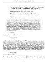
of the USART hardware. A typical Atmel USART is depicted in the block diagram you see
inside Figure 1. All ATmega AVRs contain a USART and the ATmega128 is equipped with a
pair of USARTs.
AVR USART
Clock Generator
UBRR[H:L]
OSC
BAUD RATE GENERATOR
SYNC LOGIC
Transmitter
UDR (TRANSMIT)
DATA BUS
PARITY
GENERATOR
TRANSMIT SHIFT REGISTER
PIN
CONTROL
XCK
TX CONTROL
PIN
CONTROL
TXD
RX CONTROL
CLOCK RECOVERY
Receiver
RECEIVE SHIFT REGISTER
DATA RECOVERY
UDR (RECEIVE)
PARITY CHECKER
UCSRA
UCSRB
PIN
CONTROL
RXD
USCRC
Figure 1
Atmel USARTs allow the ATmega AVRs to enter MPCM (Multi-processor Communication Mode). This mode of operation uses addressing to allow multiple processors to
communicate over the same serial bus. MPCM uses the 9-bit character frame format in
conjunction with the master/slave paradigm.
xi
Preface
The Two-wire Serial Interface
In the Atmel world, I2C is known as TWI, or Two-wire Interface. Other than a name change,
TWI looks like and smells like I2C. 128 devices can hang on the two-wire bus and are
addressed using the standard I2C 7-bit addressing scheme. Master and slave operation is
supported at speeds of up to 400 kHz. To help fight false triggering due to noise, the Atmel
TWI module includes noise suppression circuitry. You can even wake up the AVR from sleep
with a TWI.
Programming the ATmega AVR
Loading code into an ATmega AVR device is a breeze. There are many ways to accomplish
this. There’s the AVR ISP (In-System Programmer) programming module that costs less than
$40 and hooks up to a personal computer’s serial port. Or, AVR programming can be done
with the STK500 development board. ATmega AVRs with 16K or more of program memory
also support a JTAG interface, which can be used for programming the ATmega AVR program Flash. No matter how you decide to load the code into your ATmega AVR, AVR Studio
supports all of the programming devices I’ve mentioned. AVR Studio is Atmel’s front-end
IDE software that runs on a personal computer.
I’ll complement AVR Studio with ImageCraft’s ICCAVR Pro C Compiler. ICCAVR Pro
is a true ANSI-based C compiler for the ATmega AVR. I particularly like the code generator
and the AVR calculator features of ICCAVR Pro.
Emulating the ATmega AVR
At the helm of emulation for AVRs is AVR Studio. AVR Studio interfaces to the many AVR
emulation devices. In this text, the emulation device of choice is the AVR JTAG ICE. The
AVR JTAG ICE communicates with an on-chip debug module embedded within the target
AVR. The OCD (On-Chip Debugger) module in the ATmega AVRs eliminates the need for a
special bondout emulation device.
Microchip’s PIC
Most PIC microcontrollers have everything one would need to effect a network application.
Larger PICs have on-chip UARTS and USARTS for synchronous and asynchronous communications using the RS-232 protocol. A software UART function can also be implemented for
the smaller PICs that don’t have the sophistication of a built-in UART or USART module.
In networking, timing is everything. Up to three internal timers can be had on larger PIC
devices. Even the tiny 8-pin PIC12F675 has an 8-bit and a 16-bit timer. The timers can be
used for generating precision millisecond and microsecond delays or the time of day.
Fortunately, the CCS C Compiler for PIC and its native PIC peripheral routines makes it very
easy to assemble a working RS-232 PIC application. In fact, CCS C also has hooks for I2C. The
Microchip PIC family complements the CCS C peripheral routines by providing ample Flash
memory for program code, scratch pad SRAM and user data storage. The more SRAM the
better when it comes to creating buffer areas for interrupt-driven communications applications.
xii
Preface
All of our network coding and hardware design and fabrication time will be spent dealing
with the Flash-based series of the Microchip PIC family. I’ve chosen to work with the Flashbased parts because they’re inexpensive and easily obtained and don’t require the support
hardware a standard windowed PIC needs. For instance, using Flash devices eliminates the
need for an ultraviolet EPROM eraser. And, since Flash parts can be programmed and
reprogrammed in-circuit using ICSP (In-Circuit Serial Programming), fewer microcontroller
parts are needed in the development cycle since there is no need to rotate a number of parts
through the ultraviolet eraser while you’re debugging your code.
For the purposes of networking, I’ve selected the largest part in the PIC16F87X crew, the
PIC16F877. The PIC16F877 can operate with a 20 MHz clock, which gives an instruction
cycle of 200 nsec. There are 8K words of program Flash and 368 bytes of SRAM or data
memory inside a PIC16F877. Should we decide it’s necessary, there is also a block of 256
bytes of EEPROM available for storing constants or whatever else we decide is important to
keep even after the power is removed from the part. As we move into putting an RS-232
serial port together on a PIC, you’ll see how important interrupts are when it comes to
microcontrollers like the PIC. The PIC16F877 can be interrupted in 15 different ways.
I/O pins are also very important in a networking application. Not only do we need enough I/O
to perform tasks like monitoring a voltage or turning an external device on or off, there have
to be some I/O pins dedicated to the networking task. For instance, a simple micro- controller
Ethernet driver application requires at least 16 I/O pins alone. The PIC16F877 has 33 I/O lines
we can put to work, which leaves some I/O for things that microcontroller do best—control.
The PIC16F877 offers quite a bit of functionality for things other than effecting networking.
However, I’m primarily concerned with giving you the ability to network the PIC16F877.
With that, let’s start with a look at one of my favorite networking modules, the PIC16F877
USART.
The PIC16F877 USART
USART is short for Universal Synchronous/Asynchronous Receiver/Transmitter. On the
PIC, the USART is also called the SCI or Serial Communications Interface. You probably
have heard the word UART (Universal Asynchronous Receiver/Transmitter) as for many
years that was the only IC used by serial ports in personal computers. Some of today’s
microcontrollers sport UARTs instead of USARTs.
The PIC16F877 USART takes much of the pain away when it’s required to communicate
with other serial-based devices. Instead of writing timing routines to produce a specific baud
rate, the PIC16F877 USART baud rate is generated by an internal baud rate generator. With a
USART or UART, it’s not necessary to code routines to look for incoming start bits or time
the inter-bit distances to pick up the incoming data. All of that work is done within the USART
itself. A USART makes it possible to communicate with other serial devices in full-duplex or
half-duplex mode. Full-duplex mode allows communications to flow in both receive and
transmit directions simultaneously between two serial devices. Half-duplex mode only allows
one device to transmit at a time while the other device listens.
xiii
Preface
The PIC16F877 MSSP Module
MSSP, or Master Synchronous Serial Port, is yet another PIC16F877 communications
subsystem. The MSSP is a serial interface used to bring I2C applications to life. Like the
USART, the MSSP is a register and status bit-oriented module.
I2C uses six MSSP registers for control, status and buffering. Two PIC16F877 I/O pins
are dedicated to I2C, RC3 for SCL (clock) and RC4 for SDA (data). Like the USART’s
synchronous function, I2C is a master/slave communications configuration. Figure 4 is a
graphic example of how the MSSP allocates the registers, I/O pins and buffers for I2C
operation.
I2C is a Philips invention that was designed as a clever way to allow integrated circuits in
television sets and stereo rigs to talk to each other. We’ll cover I2C as it pertains to PIC
microcontrollers thoroughly in this book. Thanks to Philips, there are hundreds of I2Ccapable devices for us to play with from various manufacturers.
The PIC16F877 lends itself to oddball networking solutions. Using the PIC16F877
precision timers, we can put together a homebrew protocol and bit bang between devices. For
instance, in the past I once coded a PIC application that required the PIC to clock data to and
from a personal computer’s parallel port pin. In addition, in the early days of PIC there were
no UARTs or USARTs on the 18-pin PIC16C5X microcontrollers. Therefore, I had to code a
“software” UART to emulate the task that today’s hardware USARTs perform. You’ll find
that the software UART is still a good thing to have in your coding toolbox when designing
networking and communications applications with the tiny USART-less 8-pin PICs.
The PIC18F452
Another PIC device I’ll base networking code on in this book is the PIC18F452. The
PIC18F452 is pin-compatible with the PIC16F877. The PIC18F452 is loaded with 16K of
on-chip program memory backed up by 1.5K of SRAM. This makes the PIC18F452 a
candidate for Ethernet LAN applications. In addition to the increased internal memory area,
the PIC18F452 can run twice as fast as the PIC16F877 (40 MHz). All of the PIC16F877
communications peripherals we talked about earlier operate in the same manner on the
PIC18F452 and the CCS PIC C Compiler has the capability to generate code for them as
well.
The PIC12F675
Sometimes it’s more fun to push an economy car to its limits and not drive that performance
hot rod with all of the bells and whistles. That’s how I feel about the little 8-pin PIC12F675.
In comparison, it’s as tiny physically as it is logically. The PIC12F675 only has 1K words of
program Flash and 64 bytes of SRAM. There are only six I/O pins but inside the PIC12F675
you’ll find a couple of timers, an A/D (Analog to Digital) converter and a comparator. Like
the big guys, there is on-chip EEPROM but only 128 bytes of it. With some tricky coding,
we’ll make the tiny PIC do RS-232 with the best of them.
xiv
Preface
Programming the PIC
The Flash-based PICs that will be featured in this book are all programmed using the ICSP
(In-Circuit Serial Programming) method. As this book is focused on microcontroller communications and networking, I won’t offer up any made-in-the-garage PIC programming
hardware or software. I’m going to stick to the Microchip factory programmers and software.
You can use the Microchip MPLAB ICD 2 (In-Circuit Debugger) or the Microchip PRO
MATE II for programming the PIC Flash parts.
Emulating the PIC
The Microchip MPLAB ICD 2 and the MPLAB ICE 2000 will be used to debug and display
the inner-workings of the PIC code that will be presented in this book. I’ll be able to show
you all of the code, internal registers and memory areas using the Microchip MPLAB ICE
2000 PIC emulator system. Like the CCS C Compiler and the Microchip PRO MATE II
device programmer, the MPLAB ICE 2000 and Microchip MPLAB ICD 2 are natively
supported by Microchip’s MPLAB. The merger of the Microchip PRO MATE II, the Microchip MPLAB ICE 2000, the Microchip MPLAB ICD 2 and the CCS PIC C Compiler will
allow me to show you how things are done inside and outside the PIC using only a single
MPLAB IDE screen.
xv
What’s on the CD-ROM?
All of the source code and the executable code discussed in this book are on the companion
CD-ROM. In addition, all of the Easy Ethernet device schematics are provided in PDF format.
Printed circuit board layouts are also part of the CD-ROM package and are included for those
readers who wish to build the Easy Ethernet devices from scratch.
xvi
CHAPTER
1
The Essence of Microcontroller
Networking—RS-232
Let’s begin by exploring the RS-232 protocol. Knowing how to manipulate data with RS-232
will help you master more complex communications protocols. You’ll also find RS-232
techniques to be invaluable in the development phase of your projects.
Figure 1.1: Effecting RS-232 communications with a microcontroller is a snap. As you
continue reading this book, you will find that knowing how to implement simple
RS-232 with a microcontroller can assist you in building and debugging more complex
microcontroller projects.
The information you see in the terminal emulator window in Figure 1.1 was generated by
some very simple firmware and a not-so-complicated off-the-shelf, two-buck microcontroller.
I used a tiny 8-bit microcontroller that does not contain a built-in hardware USART (Universal Synchronous/Asynchronous Receiver/Transmitter), to transfer the ASCII characters you
see in Figure 1.1 from one of its I/O pins to an RS-232 converter IC. A serial cable connected
between the microcontroller/RS-232 converter IC circuitry and my personal computer’s serial
port allowed the ASCII characters to flow from the little microcontroller’s firmware out of the
microcontroller’s I/O pin, through the RS-232 converter IC, across the serial cable to the
personal computer’s USART/RS-232 circuitry and finally end up in the terminal emulator
window you see in Figure 1.1.
1
Chapter 1
Figure 1.2: The DTE and DCE interfaces usually consist of some sort of voltage-conversion
circuitry to translate RS-232 voltage levels to voltage levels that are compatible with
the computing equipment on each end of the communications link. The simplest form
of an RS-232 link uses only the TXD and RXD signals with a common ground.
What I’ve just described is one of the simplest forms of microcontroller networking. It is
commonly known as serial or RS-232 communications. As you can see in Figure 1.2, RS-232
was designed to tie DTE (Data Terminal Equipment) and DCE (Data Communications
Equipment) devices together electronically to effect bidirectional data communications
between the devices.
An example of a DTE device is the serial port on your personal computer. Under normal
conditions, the DTE interface on your personal computer asserts DTR (Data Terminal Ready)
and RTS (Request To Send). DTR and RTS are called modem control signals. A typical DCE
device interface responds to the assertion of DTR by activating a signal called DSR (Data Set
Ready). The DTE RTS signal is answered by CTS (Clear To Send) from the DCE device. A
standard external modem that you would connect to your personal computer serial port is a
perfect example of a DCE device.
2
The Essence of Microcontroller Networking—RS-232
Some History
In May of 1960, it was evident that a standard was needed to identify the electrical interface
between computers and modems. It was decided to establish a standard voltage with standard
signal parameters and a standard nomenclature to identify the conductors in the cable that
connected computers and data sets. Even today, you will sometimes hear the term data set
applied to modems and DCE equipment.
To compete as well as exist in the current communications environment, telecommunications vendors needed common ground to assure that each vendor’s equipment set could talk
to any other vendor’s telecommunications equipment set. In other words, the industry needed
a working standard. Without a standard, the whole teleprocessing industry could come to a
grinding, nonstandardized halt.
To help establish some harmony, a committee named the Electronic Industries Association was formed. The EIA drafted a standard known as EIA RS-232(X). Though it was a
great idea, the original specification was broad in meaning and didn’t guarantee compatibility. The new RS-232 specification also had a competitor outside the United States, known as
the CCITT, or Consultative Committee on International Telegraphy and Telephony, recommendation V.24.
The RS-232 proposal defined a logical and physical interface between DTE equipment
and DCE equipment. The computer’s DTE serial port presents both a physical and a logical
interface to a modem or data set’s DCE port and consists of several conductors for controlling, transmitting and receiving data. Timing and clocking signals are also intermixed within
the RS-232 interface. The logical and physical attributes of the RS-232 proposal eventually
became a set of standards known today as the EIA RS-232 interface.
Once the signals reach the DCE device, a second interface provides a physical path to the
communication channel (RF link, telephone line, fiber-optic link, satellite link, and so forth).
For most of you, that second interface is a standard two-conductor analog telephone line,
which is terminated inside your modem.
The EIA standard originally identified seven interface conductors and no specific connector. Signal voltages were defined as at least 3 volts but not greater than 20 volts with respect
to ground.
In October 1963, RS-232 became RS-232-A and was modified to include a 25-pin
connector with a maximum cable length of 50 feet. This revision established fixed relationships between a circuit and specific pin numbers on the 25-pin connector. Also, an alphabetic
coding system for each type of interface circuit was presented. The first character of the
coding system designated A for ground, B for data, C for control and D for clocking. Table
1.1 lays out the pinout and various names for each RS-232 signal.
3
Chapter 1
Pin
1
2
3
4
5
6
7
8
Line
Label
AA
BA
BB
CA
CB
CC
AB
CF
11
12
13
14
14
15
16
17
18
19
20
21
22
N.A.
SCF
SCB
SBA
N.A.
DB
SBB
DD
N.A.
SCA
CD
CG
CE
Line Name
Positive Ground
Transmitted Data
Received Data
Request To Send
ClearTo Send
Data Set Ready
Signal Ground
Received Line Signal Detector (RS-232);
Data Carrier Detect (RS-232A/B)
Select Standby
Secondary Receive Line Signal Detector
Secondary Clear To Send
Secondary Transmitted Data
New Sync
Transmitter Signal Element Timing
Secondary Received Data
Receiver Signal Element Timing
Test
Secondary Request To Send
Data Terminal Read
.Signal Quality Detector
Indicate
Ring/Calling
Signal
Direction
N.A.
To DCE
To DTE
To DCE
To DTE
To DTE
N.A.
To DTE
Level
To DCE
To DTE
To DTE
To DCE
To DCE
To DTE
To DTE
To DTE
To DCE
To DCE
To DCE
To DTE
To DTE
C
C
C
C
A,B,C
ABC
C
A,B,C
C
C
A,B,C
C
A,B,C
A,B C
A B,C
A,B,C
A B,C
A B,C
A B,C
ABC
A,B,C
Table 1.1: Specifications list for RS-232 interface.
There are a couple of confusion points. Note the total lack of logic when associating DB-25
pins with DB-9 pins. And, this table is based on the DTE side of the circuit. To get things to
work, you must switch the TD and RD pins on the DCE side of the circuit. When you do the
switch that puts the DTE TD pin’s data into the DCE RD pin and the DCE’s TD pin’s data
into the DTE RD pin. If you’re using the modem signals, you have to tie them together
properly between the DTE and DCE as well.
The original seven basic circuits and the signal-level definition of –3 volts for mark and
+3 volts for space were retained intact, adding ten additional optional circuit definitions. The
maximum permissible open-circuit voltage was changed to 25 volts, and a current maximum
between any two conductors, including ground, was set at 0.5 ampere. Conductors that
permit auto-answer capability were first introduced in this revision.
October 1965 brought about RS232-B, which defined terminating impedances that
permitted circuit designers to build hardware with greater reliability. Open-circuit signal
levels remained unchanged at –3 to –25 volts as mark and +3 to +25 volts as space, but
revision B added an important voltage specification. By specifying that signal ground on
pin 7 be tied to frame ground on pin 1 in the DCE equipment, a definite signal reference is
established between DTE and DCE devices.
4
The Essence of Microcontroller Networking—RS-232
The Interface Between Data Terminal Equipment and Data Communication Equipment
Employing Serial Binary Data Interchange specification was released in August 1969. It
further clarified conductor definitions and stated that properly terminated RS-232 circuits
shall not exceed ±15 volts.
RS-232-C came along later and defined the interface between Data Terminal Equipment
(DTE) and Data Circuit terminating Equipment (DCE). In the early days, a piece of DTE
hardware was usually a dumb terminal. DEC’s (Digital Equipment Corporation in those days;
Hewlett-Packard/COMPAQ these days) VT100 was and is the most well-known dumb
terminal and is still emulated today.
As you would imagine, a standard DTE device should be capable of emitting and receiving
a serial data stream. As you have already seen, that includes microcontrollers and personal
computers in the “could be a DTE” category. Although DCE equipment can also transmit and
receive a serial data stream, the primary purpose of DCE equipment is to receive the DTEgenerated bit stream over an RS-232 interface and convert it to a form that’s suitable for
transmission over a telecommunication medium. In the case of a personal computer modem,
that telecommunications medium is most likely a voice-grade telephone line.
Ever noticed that every serial port interface on your personal computer is male and every
modem serial port interface you’ve ever seen is female? There’s a reason for that. The RS-232-C
standard states that physical DTE port connectors will be male and physical DCE port
connectors will be female.
Older personal computers and modems used a 25-pin connector. Today’s 9-pin serial
connectors aren’t really standards although they have become so by proxy. The 9-pin interface first appeared commercially on AT-class PCs in the early 1980s.
RS-232 Standard Operating Procedure
Today, the majority of commercially available equipment is based on the RS-232-C or
RS-232-D standard. (The CCITT V.24 and V.28 standards are also common and widelyused.) There are 25 circuits defined in the RS-232 standard. The good news is that most of
the 25 RS-232 circuits don’t have to be used to effect an asynchronous communications
session between a DTE and DCE device. Things could be different for synchronous communications sessions that employ complex communications protocols and that’s why the timing
and clocking signals are defined in the RS-232 standard. There’s a good reason that a 9-pin
connector is on your personal computer instead of the standard appointed 25-pin connector.
You only need nine RS-232 signal lines to communicate asynchronously using a standard
asynchronous modem. Let’s look at them from a “commented” standards point of view.
■
Pin 1 (Protective Ground Circuit, AA). This conductor is bonded to the equipment
frame and can be connected to external grounds if other regulations or applications
require it.
Comment: Normally, this is either left open or connected to the signal ground. This
signal is not found in the DTE 9-pin serial connector.
5
Chapter 1
■
Pin 2 (Transmitted Data Circuit BA, TD). This is the data signal generated by the
DTE. The serial bit stream from this pin is the data that’s ultimately processed by a
DCE device.
Comment: This is pin 3 on the DTE 9-pin serial connector. This is one of the three
minimum signals required to effect an RS-232 asynchronous communications
session.
■
Pin 3 (Received Data Circuit BB, RD). Signals on this circuit are generated by the
DCE. The serial bit stream originates at a remote DTE device and is a product of the
receive circuitry of the local DCE device. This is usually digital data that’s produced
by an intelligent DCE or modem demodulator circuitry.
Comment: This is pin 2 on the DTE 9-pin serial connector. This is another of the
three minimum signals required to effect an RS-232 asynchronous communications
session.
■
Pin 4 (Request To Send Circuit CA, RTS). This signal prepares the DCE device for a
transmit operation. The RTS ON condition puts the DCE in transmit mode, while the
OFF condition places the DCE in receive mode. The DCE should respond to an RTS
ON by turning ON Clear to Send (CTS). Once RTS is turned OFF, it shouldn’t be
turned ON again until CTS has been turned OFF. This signal is used in conjunction
with DTR, DSR and DCD. RTS is used extensively in flow control.
Comment: This is pin 7 on the DTE 9-pin serial connector. In simple 3-wire implementations this signal is left disconnected. Sometimes you will see this signal tied to
the CTS signal to satisfy a need for RTS and CTS to be active signals in the communications session. You will also see RTS feed CTS in a null modem arrangement.
■
Pin 5 (Clear To Send Circuit CB, CTS). This signal acknowledges the DTE when
RTS has been sensed by the DCE device and usually signals the DTE that the DCE is
ready to accept data to be transmitted. Data is transmitted across the communications
medium only when this signal is active. This signal is used in conjunction with DTR,
DSR and DCD. CTS is used in conjunction with RTS for flow control.
Comment: This is pin 8 on the DTE 9-pin serial connector. In simple 3-wire implementations this signal is left disconnected. Otherwise, you’ll see it tied to RTS in
null modem arrangements or where CTS has to be an active participant in the communications session.
■
Pin 6 (Data Set Ready Circuit CC, DSR). DSR indicates to the DTE device that the
DCE equipment is connected to a valid communication medium and, in some cases,
indicates that the line is in the OFF HOOK condition. OFF HOOK is an indication
that the DCE is either in dialing mode or in session with another remote DCE. When
this signal is OFF, the DTE should be instructed to ignore all other DCE signals. If
this signal is turned off before DTR, the DTE is to assume an aborted communication session.
6
The Essence of Microcontroller Networking—RS-232
Comment: This is pin 6 on the DTE 9-pin serial connector. DSR is sometimes used
in a flow control arrangement with DTR. Some modems assert DSR when power to
the modem is applied regardless of the condition of the communications medium.
■
Pin 7 (Signal Common Circuit, AB). This conductor establishes the common-ground
reference for all interchange circuits, except Circuit AA, protective ground. The
RS-232-B specification permits this circuit to be optionally connected to protective
ground within the DCE device as necessary.
Comment: This is pin 5 on the DTE 9-pin serial connector and is the only ground
connection. This is the third wire of the minimal 3-wire configuration. Thus, an RS232 asynchronous communications session can be effected with only three signals:
TX (Transmit Data), RX (Receive Data) and signal ground.
■
Pin 8 (Data Carrier Detect Circuit CF, DCD). This pin is also known as Received
Line Signal Detect (RSLD) or Carrier Detect (CD). This signal is active when a
suitable carrier is established between the local and remote DCE devices. When this
signal is OFF, RD should be clamped to the mark state (binary 1).
Comment: This is pin 1 on the DTE 9-pin serial connector. Normally in use only if a
modem is in the communications signal path. You will also see this signal tied active
in a null modem arrangement.
■
Pin 20 (Data Terminal Ready Circuit CD, DTR). DTR signals are used to control
switching of the DCE to the communication medium. DTR ON indicates to the DCE
that connections in progress shall remain in progress, and if no sessions are in
progress, new connections can be made. DTR is normally turned off to initiate ON
HOOK (hang-up) conditions. The normal DCE response to activating DTR is to
activate DSR.
Comment: This is pin 4 on the DTE 9-pin serial connector. Unless you specify
differently or run a program that controls DTR, usually it is present on the personal
computer serial port as long as the personal computer is powered on. Occasionally
you will see this signal used in flow control.
■
Pin 22 (Ring Indicator Circuit CE, RI). The ON condition of this signal indicates
that a ring signal is being received from the communication medium (telephone line).
It’s normally up to the control program to act on the presence of this signal.
Comment: This is pin 9 on the DTE 9-pin serial connector. This signal follows the
incoming ring to an extent. Normally, this signal is used by DCE auto-answer
algorithms.
That is all that’s needed RS-232 signal-wise to establish a session between a DTE and a
DCE device. Now that you have a feeling for what each RS-232 signal does, let’s review how
they react to each other with respect to the transfer of data between a DTE and DCE device.
7
Chapter 1
■
Local DTE (personal computer, microcontroller, etc.) is powered up and DTR is
asserted.
■
Local DCE (modem, data set, microcontroller, etc.) is powered up and senses the
DTR from the local DTE.
■
Local DCE asserts DSR. If the DCE device is a modem, it goes off-hook (picks up
the line). If a dial-up session is to be established, the DTE sends a dial instruction
and phone number to the modem.
■
If the line is good and the other end (remote DCE) is ready or answers the dial-up
from the local DCE, a carrier is generated/detected and the local and remote DCE
devices assert DCD. The session is established.
■
The transmitting DTE raises RTS.
■
The transmitting DCE responds with CTS.
■
The control program transmits or receives data.
In our historical review, the DTE or personal computer and DCE or modem took care of
converting the RS-232 signal levels to appropriate personal computer circuitry levels. To
perform RS-232 asynchronous communications with microcontrollers, we must employ a
voltage translation scheme of our own. Fortunately, there are many ways to do this and all of
them are easy to implement.
RS-232 Voltage Conversion Considerations
RS-232 converter ICs like those made by Maxim and Sipex convert the negative RS-232
voltages to positive logic voltage levels that microcontroller circuits can understand. The
positive RS-232 voltages are converted to a microcontroller’s logical 0 (zero) voltage level. If
the microcontroller circuitry is powered by +5 VDC, then an RS-232 ‘1’ or mark is converted
to a TTL (Transistor Transistor Logic) high or ‘1’ and an RS-232 ‘0’ or space is translated
into a TTL low or ‘0’. With the advent of 3-volt logic, special RS-232 converter ICs that can
operate at the 3-volt power supply levels have been introduced. The bottom line is that the
RS-232 marks and spaces must be converted to voltage levels the microcontroller can understand before any communications and data transfer can be realized between devices.
In reality, the full-positive and negative voltage swing called out by the RS-232 standard
doesn’t have to be employed to effect RS-232 communications links. With the right cable an
RS-232 voltage of –3 volts is sufficient to generate a ‘1’ or mark while +3 volts will produce
a ‘0’ or space. The area between –3 volts and +3 volts (shown in Figure 1.3) is a transition
zone and is where most of the nasty line noise can and should be found. By defining this
±3-volt threshold, the signal-to-noise ratio of the RS-232 physical link is improved. If a
high-quality serial cable is used and the distance between stations is relatively short, RS-232
voltages that resemble microcontroller logic voltages can be used to transfer information
8
The Essence of Microcontroller Networking—RS-232
Figure 1.3: Cheap RS-232 implementations dare to use the 0 VDC to +5 VDC region for
marks and spaces with 0 VDC being a mark and anything over +3 VDC representing a
space. The “NOISE ZONE” I’ve marked is actually called the transition zone.
between a DTE and DCE device. In addition, using a high-quality cable could extend the 50foot maximum cable length specified by the RS-232 specification. Reducing the speed of the
data transmission can also extend the maximum cable length between a wired set of DTE and
DCE devices as well.
The good news is that you don’t have to know the nitty-gritty details of the RS-232
specification to use RS-232 as a means of communicating with a microcontroller. In fact, I’ve
already given you more RS-232 history and theory than you really need to know to make a
microcontroller talk asynchronously. In this book, we’re all about the practical application of
RS-232 as it pertains to microcontrollers. So, let’s look at some RS-232 hardware and the
firmware behind it.
9
[This is a blank page.]
CHAPTER
2
Implementing RS-232 with a Microcontroller
Now that you’ve completed RS-232 history 101, this chapter will deal with implementing
RS-232 on a microcontroller. We’ll use the Microchip® PIC12F675 as our RS-232 engine and
we’ll power our RS-232 engine with code written with the Custom Computer Services C
Compiler.
You can build the circuits in this chapter from scratch. I’ve chosen to use the Microchip
PICkit™ 1 as my “breadboard” as it contains circuitry to program the PIC12F675 and an
experimenter area that is perfectly suited for additional RS-232 circuitry.
Basic RS-232 Hardware
Let’s begin by looking at a simple microcontroller implementation. In its most basic form, an
operational microcontroller-based circuit consists of the microcontroller, a simple power
supply and a clock source. For this project, I’m going to use the most basic of
microcontrollers, an 8-pin Microchip PIC12F675.
The PIC12F675 has an internal clock source but does not contain a USART. That means
we will have to implement the functionality of a hardware USART in the PIC12F675’s
firmware. To do that, we need to know just a bit more about RS-232 signaling. Let’s begin by
designating the desired RS-232 signaling speed, or baud rate. A common baud rate is 9600 bps
(bits per second) and most everything RS-232 can operate at this speed. So, 9600 bps it is.
At 9600 bps, our data packet bit width is the reciprocal of the baud rate, which is 104 µS
(104 microseconds). The idea is to try to see if the incoming RS-232 bit is a ‘1’ or ‘0’ by
having the PIC12F675 microcontroller USART program check the incoming bit in the dead
center of the 104 µS bit width. Since our baud rate is 9600 bps and our bit width for 9600bps
is 104 µS, that means we must have the microcontroller check the incoming bit stream every
104 µS.
There are still other things to consider. For instance, how does the microcontroller know
when to start and stop the 104µS bit check intervals? For the answer, let’s draw again from
the RS-232 specification. We assigned a speed of 9600 bps for our data stream. However, we
must also specify how many data bits will be transmitted and received in a data packet and
how many stop bits will indicate the end of the data packet. We do have a choice as to the
number of data bits we can stash into a data packet. The data packet bit length choices are 5
bits, 7 bits, 8 bits and 9 bits. Since the PIC12F675 is an 8-bit device, let’s designate a data
11