src air bag control system
Bạn đang xem bản rút gọn của tài liệu. Xem và tải ngay bản đầy đủ của tài liệu tại đây (2.87 MB, 90 trang )
RESTRAINTS
SECTION
SRC
SRS AIRBAG CONTROL SYSTEM
A
B
C
D
E
CONTENTS
PRECAUTION ............................................... 3
DIAGNOSIS SYSTEM (AIR BAG) .................... 13
Precaution for Supplemental Restraint System
(SRS) "AIR BAG" and "SEAT BELT PRE-TENSIONER" ................................................................... 3
Precaution for SRS "AIR BAG" and "SEAT BELT
PRE-TENSIONER" Service ...................................... 3
Diagnosis Description ..............................................13
SRS Operation Check .............................................13
Trouble Diagnosis with CONSULT ..........................14
Trouble Diagnosis without CONSULT .....................15
SRS History Check ..................................................15
SRS Final Check .....................................................15
CONSULT Function (AIR BAG) ...............................15
SYSTEM DESCRIPTION .............................. 4
ECU DIAGNOSIS INFORMATION .............. 17
COMPONENT PARTS ........................................ 4
DIAGNOSIS SENSOR UNIT ............................. 17
PRECAUTIONS ................................................... 3
Component Parts Location ........................................ 4
Component Description ............................................. 4
Driver Air Bag Module ............................................... 5
Front Passenger Air Bag Module .............................. 5
Front Side Air Bag Module ........................................ 5
Side Curtain Air Bag Module ..................................... 5
Front Seat Belt Pre-tensioner .................................... 6
Air Bag Diagnosis Sensor Unit .................................. 6
Crash Zone Sensor ................................................... 6
Side Air Bag Satellite Sensor .................................... 7
Door Satellite Sensor ................................................ 7
SRS Component Connectors .................................... 7
SYSTEM .............................................................. 9
SRS AIR BAG SYSTEM .............................................. 9
SRS AIR BAG SYSTEM : System Diagram .............. 9
SRS AIR BAG SYSTEM : System Description ......... 9
OCCUPANT CLASSIFICATION SYSTEM .................. 9
OCCUPANT CLASSIFICATION SYSTEM : System Diagram ............................................................ 10
OCCUPANT CLASSIFICATION SYSTEM : System Description ....................................................... 10
SEAT BELT WARNING LAMP SYSTEM .................. 11
SEAT BELT WARNING LAMP SYSTEM : System
Diagram ................................................................... 11
SEAT BELT WARNING LAMP SYSTEM : System
Description .............................................................. 12
Revision: March 2013
Downloaded from www.Manualslib.com manuals search engine
DTC Index ...............................................................17
Flash Code Index ....................................................20
F
G
SRC
I
J
WIRING DIAGRAM ...................................... 24
SRS AIR BAG CONTROL SYSTEM ................. 24
Wiring Diagram ........................................................24
BASIC INSPECTION ................................... 33
K
L
DIAGNOSIS AND REPAIR WORK FLOW ....... 33
Work Flow ................................................................33
INSPECTION AND ADJUSTMENT .................. 35
ADDITIONAL SERVICE WHEN REPLACING
CONTROL UNIT ........................................................35
ADDITIONAL SERVICE WHEN REPLACING
CONTROL UNIT : Description .................................35
ADDITIONAL SERVICE WHEN REPLACING
CONTROL UNIT : Special Repair Requirement ......35
ZERO POINT RESET .................................................35
ZERO POINT RESET : Description .........................35
ZERO POINT RESET : Special Repair Requirement .........................................................................35
INTERMITTENT INCIDENT .............................. 36
Inspection Procedure ..............................................36
Trouble Diagnosis with CONSULT ..........................36
SRC-1
2012 Versa Sedan
M
N
O
P
DTC/CIRCUIT DIAGNOSIS ......................... 37
B1113 – B1115 SATELLITE SENSOR RH ....... 67
B1049 – B1052, B1054 – B1057 DRIVER AIRBAG MODULE ................................................... 37
Description .............................................................. 67
DTC Logic ............................................................... 67
Diagnosis Procedure ............................................... 68
Description .............................................................. 37
DTC Logic ............................................................... 37
Diagnosis Procedure (Component Diagnosis) ........ 38
B1065 – B1068, B1070 – B1073 PASSENGER AIRBAG MODULE .................................... 40
Description .............................................................. 40
DTC Logic ............................................................... 40
Diagnosis Procedure (Component Diagnosis) ........ 41
B1134 – B1137 SIDE AIRBAG MODULE LH ... 43
Description .............................................................. 43
DTC Logic ............................................................... 43
Diagnosis Procedure (Component Diagnosis) ........ 44
B1129 – B1132 SIDE AIRBAG MODULE RH ... 46
Description .............................................................. 46
DTC Logic ............................................................... 46
Diagnosis Procedure (Component Diagnosis) ........ 47
B1150 – B1153 SIDE CURTAIN AIR BAG
MODULE LH ...................................................... 49
Description .............................................................. 49
DTC Logic ............................................................... 49
Diagnosis Procedure (Component Diagnosis) ........ 50
B1145 – B1148 SIDE CURTAIN AIR BAG
MODULE RH ...................................................... 52
Description .............................................................. 52
DTC Logic ............................................................... 52
Diagnosis Procedure (Component Diagnosis) ........ 53
B1086 – B1089 SEAT BELT PRE-TENSIONER LH ................................................................. 55
Description .............................................................. 55
DTC Logic ............................................................... 55
Diagnosis Procedure .............................................. 56
B1081 – B1084 SEAT BELT PRE-TENSIONER RH ................................................................ 58
Description .............................................................. 58
DTC Logic ............................................................... 58
Diagnosis Procedure .............................................. 59
B1033 – B1035 CRASH ZONE SENSOR ......... 61
Description .............................................................. 61
DTC Logic ............................................................... 61
Diagnosis Procedure .............................................. 62
B1118 – B1120 SATELLITE SENSOR LH ........ 64
Description .............................................................. 64
DTC Logic ............................................................... 64
Diagnosis Procedure .............................................. 65
Revision: March 2013
Downloaded from www.Manualslib.com manuals search engine
B1343 - B1349 FRONT DOOR SATELLITE
SENSOR LH ...................................................... 70
Description .............................................................. 70
DTC Logic ............................................................... 70
Diagnosis Procedure (Component Diagnosis) ........ 71
B1336 - B1342 FRONT DOOR SATELLITE
SENSOR RH ...................................................... 73
Description .............................................................. 73
DTC Logic ............................................................... 73
Diagnosis Procedure (Component Diagnosis) ........ 74
B1350 FRONT DOOR SATELLITE SENSORS
... 76
Description .............................................................. 76
DTC Logic ............................................................... 76
Diagnosis Procedure (Component Diagnosis) ........ 77
B1XXX AIR BAG DIAGNOSIS SENSOR UNIT... 79
Description .............................................................. 79
DTC Logic ............................................................... 79
Diagnosis Procedure ............................................... 80
B1023 PASSENGER AIR BAG OFF INDICATOR .................................................................... 81
Description .............................................................. 81
DTC Logic ............................................................... 81
Diagnosis Procedure (Component Diagnosis) ........ 82
B1017, B1018, B1020, B1021, B1022, B1025,
B1032, B1048 OCS SYSTEM ........................... 84
Description .............................................................. 84
DTC Logic ............................................................... 84
Diagnosis Procedure (Component Diagnosis) ........ 85
B1209 – B1210 COLLISION DETECTION ........ 87
Description .............................................................. 87
DTC Logic ............................................................... 87
Diagnosis Procedure (Component Diagnosis) ........ 87
SYMPTOM DIAGNOSIS ............................ 88
SRS AIR BAG WARNING LAMP DOES NOT
TURN ON ........................................................... 88
AIR BAG Warning Lamp Does Not Turn On ........... 88
SRS AIR BAG WARNING LAMP DOES NOT
TURN OFF ......................................................... 89
AIR BAG Warning Lamp Does Not Turn Off ........... 89
SEAT BELT WARNING SYSTEM ..................... 90
Seat Belt Warning System Does Not Function ....... 90
SRC-2
2012 Versa Sedan
PRECAUTIONS
< PRECAUTION >
PRECAUTION
A
PRECAUTIONS
Precaution for Supplemental Restraint System (SRS) "AIR BAG" and "SEAT BELT
PRE-TENSIONER"
B
INFOID:0000000007618785
The Supplemental Restraint System such as “AIR BAG” and “SEAT BELT PRE-TENSIONER”, used along
with a front seat belt, helps to reduce the risk or severity of injury to the driver and front passenger for certain
types of collision. This system includes seat belt switch inputs and dual stage front air bag modules. The SRS
system uses the seat belt switches to determine the front air bag deployment, and may only deploy one front
air bag, depending on the severity of a collision and whether the front occupants are belted or unbelted.
Information necessary to service the system safely is included in the SR and SB section of this Service Manual.
WARNING:
• To avoid rendering the SRS inoperative, which could increase the risk of personal injury or death in
the event of a collision which would result in air bag inflation, all maintenance must be performed by
an authorized NISSAN/INFINITI dealer.
• Improper maintenance, including incorrect removal and installation of the SRS, can lead to personal
injury caused by unintentional activation of the system. For removal of Spiral Cable and Air Bag
Module, see the SR section.
• Do not use electrical test equipment on any circuit related to the SRS unless instructed to in this
Service Manual. SRS wiring harnesses can be identified by yellow and/or orange harnesses or harness connectors.
PRECAUTIONS WHEN USING POWER TOOLS (AIR OR ELECTRIC) AND HAMMERS
WARNING:
• When working near the Airbag Diagnosis Sensor Unit or other Airbag System sensors with the Ignition ON or engine running, DO NOT use air or electric power tools or strike near the sensor(s) with a
hammer. Heavy vibration could activate the sensor(s) and deploy the air bag(s), possibly causing
serious injury.
• When using air or electric power tools or hammers, always switch the Ignition OFF, disconnect the
battery and wait at least three minutes before performing any service.
C
D
E
F
G
SRC
I
J
Precaution for SRS "AIR BAG" and "SEAT BELT PRE-TENSIONER" Service
INFOID:0000000007605423
• Do not use electrical test equipment to check SRS circuits unless instructed to in this Service Manual.
• Before servicing the SRS, turn ignition switch OFF, disconnect both battery cables and wait at least 3 minutes.
For approximately 3 minutes after the cables are removed, it is still possible for the air bag and seat belt pretensioner to deploy. Therefore, do not work on any SRS connectors or wires until at least 3 minutes have
passed.
• The air bag diagnosis sensor unit must always be installed with the arrow mark “⇐” pointing toward the front
of the vehicle for proper operation. Also check air bag diagnosis sensor unit for cracks, deformities or rust
before installation and replace as required.
• The spiral cable must be aligned with the neutral position since its rotations are limited. Do not attempt to
turn steering wheel or column after removal of steering gear.
• Handle air bag module carefully. Always place driver and front passenger air bag modules with the pad side
facing upward and seat mounted front side air bag module standing with the stud bolt side facing down.
• Conduct self-diagnosis to check entire SRS for proper function after replacing any components.
• After air bag inflates, the front instrument panel assembly should be replaced if damaged.
K
L
M
N
O
P
Revision: March 2013
Downloaded from www.Manualslib.com manuals search engine
SRC-3
2012 Versa Sedan
COMPONENT PARTS
< SYSTEM DESCRIPTION >
SYSTEM DESCRIPTION
COMPONENT PARTS
Component Parts Location
INFOID:0000000007605494
AWHIA0271ZZ
1.
Crash zone sensor
2.
Front door satellite sensor LH
3.
Spiral cable
4.
Front passenger air bag off indicator
5.
Front LH seatbelt pre-tensioner
Side air bag satellite sensor LH
6.
Air bag diagnosis sensor unit
7.
Front LH side air bag module
8.
Seat belt buckle switch (LH)
Seat belt buckle switch (RH)
9.
Occupant classification system control
unit and sensors
10. Front RH seatbelt pre-tensioner
Side air bag satellite sensor RH
11. Front RH side air bag module
12. RH side curtain air bag module
13. Front door satellite sensor RH
14. LH side curtain air bag module
15. Front passenger air bag module
16. Driver air bag module
Component Description
INFOID:0000000007605425
Component
Function
Air bag diagnosis sensor unit
Refer to SRC-6, "Air Bag Diagnosis Sensor Unit".
Driver air bag module
Refer to SRC-5, "Driver Air Bag Module".
Front passenger air bag module
Refer to SRC-5, "Front Passenger Air Bag Module".
Front side air bag module
Refer to SRC-5, "Front Side Air Bag Module".
Side curtain air bag module
Refer to SRC-5, "Side Curtain Air Bag Module".
Front seat belt pre-tensioner
Refer to SRC-6, "Front Seat Belt Pre-tensioner".
Occupant classification system
Refer to SRC-10, "OCCUPANT CLASSIFICATION SYSTEM : System Description".
Crash zone sensor
Refer to SRC-6, "Crash Zone Sensor".
Side air bag (satellite) sensor
Refer to SRC-7, "Side Air Bag Satellite Sensor".
Revision: March 2013
Downloaded from www.Manualslib.com manuals search engine
SRC-4
2012 Versa Sedan
COMPONENT PARTS
< SYSTEM DESCRIPTION >
Component
Function
A
Front door (satellite) sensor
Refer to SRC-7, "Door Satellite Sensor".
Seat belt buckle switch
The seat belt buckle switches (LH/RH) provide the seat belt buckle signals to the air bag diagnosis
sensor unit and the combination meter.
Spiral cable
The spiral cable provides a rotating physical connection to the driver air bag module.
Combination meter
The combination meter displays the air bag warning lamp and the seat belt warning lamp. The
air bag warning lamp is used for diagnosis in User Mode and may be used to display diagnostic
trouble codes without the use of the CONSULT.
Driver Air Bag Module
B
C
INFOID:0000000007605426
D
The driver air bag module is dual stage and located in the steering
wheel assembly. It operates with the SRS system in a frontal collision exceeding a specified level.
E
F
G
AWHIA0319ZZ
Front Passenger Air Bag Module
INFOID:0000000007605495
The front passenger air bag module is located behind the instrument
panel assembly. It operates with the SRS system in a frontal collision exceeding a specified level. Refer to SRC-10, "OCCUPANT
CLASSIFICATION SYSTEM : System Description" for more information.
SRC
I
J
K
AWHIA0320ZZ
Front Side Air Bag Module
INFOID:0000000007605428
L
Front side air bag modules are built into the front seatback assemblies. Vehicles with side air bags are equipped with labels as shown.
M
N
O
AWHIA0333ZZ
Side Curtain Air Bag Module
INFOID:0000000007605429
Side curtain air bag modules are located above the vehicle headlining.
Revision: March 2013
Downloaded from www.Manualslib.com manuals search engine
SRC-5
2012 Versa Sedan
P
COMPONENT PARTS
< SYSTEM DESCRIPTION >
Vehicles with side curtain air bags are equipped with labels on the
center pillar upper finisher as shown.
WHIA0041E
Front Seat Belt Pre-tensioner
INFOID:0000000007605430
The seat belt pre-tensioner system with load limiter is installed for
both the driver's seat and the front passenger's seat. It operates
simultaneously with the SRS air bag system in the event of a frontal
collision with an impact exceeding a specified level.
When the frontal collision with an impact exceeding a specified level
occurs, seat belt slack resulting from clothing or other factors is
immediately taken up by the pre-tensioner. Vehicle passengers are
securely restrained.
When passengers in a vehicle are thrown forward in a collision and
the restraining force of the seat belt exceeds a specified level, the
load limiter permits the specified extension of the seat belt by the
twisting of the ELR shaft, and a relaxation of the chest-area seat belt
web tension while maintaining force.
Air Bag Diagnosis Sensor Unit
AWHIA0321ZZ
INFOID:0000000007605431
The air bag diagnosis sensor unit is located under the center console. The air bag diagnosis sensor unit receives signals from multiple SRS sensors and controls the deployment of the air bags. The
deployment of the air bags depends on the type and severity of the
collision. The air bag diagnosis sensor unit has self-diagnosis capability through the use of the CONSULT as well as flash codes displayed by the air bag warning lamp.
AWHIA0322ZZ
Crash Zone Sensor
INFOID:0000000007605432
The crash zone sensor is located behind the front grille in front of the
radiator support. The crash zone sensor sends signals to the air bag
diagnosis sensor unit during a frontal collision. This sensor may be
identified by a yellow connector.
AWHIA0323ZZ
Revision: March 2013
Downloaded from www.Manualslib.com manuals search engine
SRC-6
2012 Versa Sedan
COMPONENT PARTS
< SYSTEM DESCRIPTION >
Side Air Bag Satellite Sensor
INFOID:0000000007605433
A
The side air bag satellite sensors are located on the center pillar LH
and RH next to the seat belt pretensioners. The side air bag satellite
sensors send signals to the air bag diagnosis sensor unit during a
side collision. These sensors may be identified by yellow connectors.
B
C
D
AWHIA0324ZZ
Door Satellite Sensor
INFOID:0000000007605496
The front door satellite sensors are located in the driver and passenger doors. The front door satellite sensors send signals to the air
bag diagnosis sensor unit during a side collision. These sensors
may be identified by yellow connectors.
E
F
G
SRC
AWHIA0325ZZ
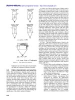
SRS Component Connectors
INFOID:0000000007605497
I
DIRECT CONNECT
The following SRS components use direct-connect style harness connectors.
• Driver front air bag module
• Passenger front air bag module
• LH side curtain air bag module
• RH side curtain air bag module
• Front LH seat belt pre-tensioner
• Front RH seat belt pre-tensioner
Always pull up to release locking tab prior to removing connector from SRS component.
Always push down to lock locking tab after installing connector to
SRS component. When locked, the locking tab is level with the connector housing.
J
K
L
M
N
O
WHIA0103E
SLIDE DOUBLE LOCKING
• A new style slide double locking type connector is used on certain systems and components, especially
those related to airbag control systems.
• The slide double locking type connectors help prevent incomplete locking and accidental looseness or disconnection.
• The slide double locking type connectors are disconnected by pushing or pulling the slider. Refer to the figure below.
CAUTION:
Revision: March 2013
Downloaded from www.Manualslib.com manuals search engine
SRC-7
2012 Versa Sedan
P
COMPONENT PARTS
< SYSTEM DESCRIPTION >
• Do not pull the harness or wires when disconnecting the connector.
AAMIA0498GB
Revision: March 2013
Downloaded from www.Manualslib.com manuals search engine
SRC-8
2012 Versa Sedan
SYSTEM
< SYSTEM DESCRIPTION >
SYSTEM
A
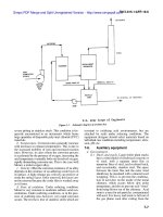
SRS AIR BAG SYSTEM
SRS AIR BAG SYSTEM : System Diagram
INFOID:0000000007605435
B
C
D
E
F
G
SRC
I
AWHIA0326GB
SRS AIR BAG SYSTEM : System Description
INFOID:0000000007605436
• The air bag deploys if the air bag diagnosis sensor unit is activated while the ignition switch is in the ON or
START position.
• The collision modes for which supplemental restraint systems are activated are different among the SRS
systems. For example, the driver air bag module, front passenger air bag module and front seat belt pre-tensioners are activated in a frontal collision but not in a side collision.
J
K
L
SRS Collision Modes
SRS configuration
Driver air bag module
Frontal collision
Left side collision
Right side collision
x
—
—
Front passenger air bag module
x
—
—
Front LH seat belt pre-tensioner
x
—
—
Front RH seat belt pre-tensioner
x
—
—
Front LH side air bag module
—
x
—
Front RH side air bag module
—
—
x
LH side curtain air bag module
—
x
—
RH side curtain air bag module
—
—
x
OCCUPANT CLASSIFICATION SYSTEM
Revision: March 2013
Downloaded from www.Manualslib.com manuals search engine
SRC-9
2012 Versa Sedan
M
N
O
P
SYSTEM
< SYSTEM DESCRIPTION >
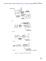
OCCUPANT CLASSIFICATION SYSTEM : System Diagram
INFOID:0000000007618790
AWHIA0338GB
OCCUPANT CLASSIFICATION SYSTEM : System Description
INFOID:0000000007618791
The occupant classification system (OCS) identifies different size occupants, out of position occupants, and
detects if child seat is present in the front passenger seat. The OCS control unit (2) receives inputs from the
occupant classification sensors (1) (located inside the passenger seat cushion assembly). Depending on classification of the passenger, the OCS sends a signal to the air bag diagnosis sensor unit. The air bag diagnosis
sensor unit uses this signal and the seat belt buckle switch RH signal to determine deployment or non deployment of the passenger front air bag in the event of a collision. Depending on the signals received, the air bag
diagnosis sensor unit can disable the passenger front air bag completely. The OCS (weight sensors) must be
set to zero point using CONSULT after servicing the OCS system.
NOTE:
• CONSULT can be used to confirm when “zero point reset” for OCS is complete.
• Always perform zero point reset after the removal and installation of the seat or when disconnecting the
OCS control unit harness connector even if zero point reset has been completed in the past.
• If zero point reset is incomplete, the passenger air bag will be disabled and the passenger air bag off indicator will be ON.
• In case of customer concern, CONSULT can be used to confirm the passenger air bag status (readiness).
Passenger Air Bag Status Conditions
Front Passenger Seat
(Condition)
PASS AIR BAG OFF Indicator
(Status)
Passenger Air Bag Status
(Readiness)
CONSULT Display
Seat occupied
OFF
Active (enabled)
ON
Seat occupied NOTE
ON
Deactivated (disabled)
OFF
Seat empty
OFF
Deactivated (disabled)
OFF
NOTE:
Revision: March 2013
Downloaded from www.Manualslib.com manuals search engine
SRC-10
2012 Versa Sedan
SYSTEM
< SYSTEM DESCRIPTION >
Passenger does not meet Occupant Classification System specifications for passenger air bag activation.
A
B
C
D
E
F
G
AWHIA0339ZZ
SRC
SEAT BELT WARNING LAMP SYSTEM
SEAT BELT WARNING LAMP SYSTEM : System Diagram
INFOID:0000000007618786
I
J
K
L
M
N
ALHIA0028GB
O
P
Revision: March 2013
Downloaded from www.Manualslib.com manuals search engine
SRC-11
2012 Versa Sedan
SYSTEM
< SYSTEM DESCRIPTION >
SEAT BELT WARNING LAMP SYSTEM : System Description
INFOID:0000000007618787
The seat belt warning lamp (1) will remind the driver if the driver or front passenger seat belt should be buckled. The system works in conjunction with the occupant classification system. Refer to SRC-10, "OCCUPANT
CLASSIFICATION SYSTEM : System Description".
AWHIA0337ZZ
Seat Belt Warning System Operation
Driver seat status
(Ignition switch ON)
Passenger seat status
Seat occupied
Seat occupied
Buckled
Seat unoccupied
—
Revision: March 2013
Seat belt buckle switch
LH status
Downloaded from www.Manualslib.com manuals search engine
Unbuckled
SRC-12
Seat belt buckle switch
RH status
Seat belt warning lamp
Buckled
Off
Unbuckled
On
—
Off
On
2012 Versa Sedan
DIAGNOSIS SYSTEM (AIR BAG)
< SYSTEM DESCRIPTION >
DIAGNOSIS SYSTEM (AIR BAG)
A
Diagnosis Description
INFOID:0000000007605439
CAUTION:
• Do not use electrical test equipment on any circuit related to the SRS unless instructed to do so in
this Service Manual. SRS wiring harnesses can be identified by yellow and/or orange harness connectors.
• Do not attempt to repair, splice or modify SRS wiring harnesses. If a harness is damaged, replace it
with a new one.
• Keep ground connections clean.
C
D
HOW TO PERFORM TROUBLE DIAGNOSES FOR QUICK AND ACCURATE REPAIR
1.
2.
-
B
Obtain information about the symptom.
WHAT - vehicle model
WHEN - date, frequencies
WHERE - road conditions
HOW - operating conditions, symptoms, passengers
Perform Preliminary Check.
Battery
Fuses
Harness connections
E
F
G
DIAGNOSIS METHODS
SRS self-diagnosis results can be read by using the AIR BAG warning lamp or CONSULT.
The User Mode is for the customer (driver). This mode warns the driver of a system malfunction through the
SRC
the AIR BAG warning lamp.
The Diagnosis Mode is for the technician. This mode helps the technician locate the malfunctioning circuit or
part.
I
User Mode
Diagnosis Mode
Display type
AIR BAG warning lamp
X
X
ON/OFF
CONSULT
—
X
Monitoring
SRS Operation Check
J
INFOID:0000000007605440
K
USER MODE
1.
2.
Turn the ignition switch from OFF to ON and check that the air bag warning lamp blinks.
Compare the blinking pattern with the examples in the table.
L
M
N
BF-1845D
O
P
Revision: March 2013
Downloaded from www.Manualslib.com manuals search engine
SRC-13
2012 Versa Sedan
DIAGNOSIS SYSTEM (AIR BAG)
< SYSTEM DESCRIPTION >
Air bag warning lamp flashing pattern (User Mode)
Warning lamp
SRS condition
Reference item
• No malfunction is detected.
• No further action is necessary.
—
The system is malfunctioning and
needs to be repaired.
Refer to SRC-14, "Trouble Diagnosis with CONSULT" or SRC-15,
"Trouble Diagnosis without CONSULT".
Zero point reset is incomplete
Refer to SRC-35, "ZERO POINT
RESET : Special Repair Requirement".
• Air bag is deployed.
• Seat belt pre-tensioner is deployed.
Refer to SR-4, "For Frontal Collision"
or SR-6, "For Side and Rollover Collision".
• Air bag diagnosis sensor unit is malfunctioning.
• Air bag power supply circuit is malfunctioning.
• SRS air bag warning lamp circuit is
malfunctioning.
Refer to SRC-89, "AIR BAG Warning Lamp Does Not Turn Off".
• Air bag diagnosis sensor unit is malfunctioning.
• Air bag warning lamp circuit is malfunctioning.
Refer to SRC-88, "AIR BAG Warning Lamp Does Not Turn On".
SHIA0011E
SHIA0012E
SHIA0013E
SHIA0014E
Trouble Diagnosis with CONSULT
1.
2.
INFOID:0000000007605441
Connect CONSULT.
DTC is displayed on SELF-DIAG RESULTS.
NOTE:
If a malfunction is not detected on SELF-DIAG RESULTS [CURRENT], but a malfunction is detected during
SRS Operation Check, the following cases may exist:
• SELF-DIAG [PAST] memory might not be erased. Refer to SRC-15, "SRS Final Check".
• SRS system malfunctions intermittently. Refer to SRC-36, "Inspection Procedure".
Revision: March 2013
Downloaded from www.Manualslib.com manuals search engine
SRC-14
2012 Versa Sedan
DIAGNOSIS SYSTEM (AIR BAG)
< SYSTEM DESCRIPTION >
Trouble Diagnosis without CONSULT
INFOID:0000000007605442
A
DIAGNOSIS MODE
NOTE:
Diagnosis Mode can not be entered if a malfunction is not detected in User Mode.
1. Turn ignition switch ON.
2. After AIR BAG warning lamp lights for 7 seconds, turn ignition switch OFF within 1 second.
3. Wait more than 3 seconds.
4. Repeat steps 1 to 3 two more times (3 times total).
5. Turn ignition switch ON.
SRS is now in Diagnosis Mode. Refer to SRC-20, "Flash Code Index".
SRS History Check
B
C
D
INFOID:0000000007605443
SRS HISTORY CHECK
1.
2.
Check repair history of the SRS. If no repairs have been made perform SRC-13, "SRS Operation Check".
If repairs have been made GO TO step 2.
Erase "SELF-DIAG [PAST]" after repair. Refer to SRC-15, "SRS Final Check".
SRS Final Check
E
F
INFOID:0000000007605444
DIAGNOSIS MODE
1.
2.
3.
4.
5.
6.
7.
G
Connect CONSULT.
Confirm that zero point reset of OCS is complete.
If no DTCs are detected on “SELF-DIAG RESULTS [CURRENT]”, repair of SRS is completed. Go to step
SRC
4.
If any DTCs are detected on “SELF-DIAG RESULTS [CURRENT]”, the malfunction has not been repaired
completely or another malfunction is being detected. Perform SRS Operation Check again. Refer to
I
SRC-13, "SRS Operation Check".
Touch “ERASE”.
NOTE:
Touching “ERASE” will clear the SRS memory of the malfunction (“SELF-DIAG [PAST]”). If “SELF- J
DIAG [PAST]” is not erased, User Mode may show the previous system malfunction even if the
malfunction has been repaired completely.
Check that no malfunction is detected in “SELF-DIAG [PAST]”.
K
Exit Diagnosis Mode and disconnect the CONSULT.
Perform SRS Operation Check. Refer to SRC-13, "SRS Operation Check".
CONSULT Function (AIR BAG)
INFOID:0000000007605445
L
CONSULT can display each diagnostic item using the diagnostic test modes shown following.
Diagnostic Test Mode
M
Diagnostic Item
Description
ECU DISCRIMINATED NO.
Air bag diagnosis sensor unit ECU discriminated number (identification
number) or part number is displayed. Air bag diagnosis sensor unit has
individual ECU discriminated number (identification number) or part
number based on model and equipment.
Self Diagnostic Result
SELF-DIAG RESULT [CURRENT]
A current Self-diagnosis result (also indicated by the number of warning
lamp flashes in the Diagnosis mode) is displayed on the CONSULT
screen in real time. This refers to a malfunctioning part requiring repairs.
Work Support
ZERO POINT RESET FUNCTION
Perform zero point reset. Refer to SRC-35, "ZERO POINT RESET : Special Repair Requirement".
Function Test
CAR COMPUTER DIAG.
Ecu Identification
Revision: March 2013
Downloaded from www.Manualslib.com manuals search engine
System wide test results are indicated.
SRC-15
2012 Versa Sedan
N
O
P
DIAGNOSIS SYSTEM (AIR BAG)
< SYSTEM DESCRIPTION >
Diagnostic Test Mode
Special function
Diagnostic Item
Description
SELF-DIAG [PAST]
Diagnosis results previously stored in the memory are displayed on the
CONSULT screen. The stored results will remain until memory erasing
is executed.
TROUBLE DIAG RECORD
With TROUBLE DIAG RECORD, diagnosis results previously erased by
a reset operation can be displayed on the CONSULT screen.
SELF-DIAG RESULT [CAN]
A current Self-diagnosis result [CAN] is displayed on the CONSULT
screen in real time. Self-diagnosis result [CAN] can not be erased.
CAUSE OF WARNING
Revision: March 2013
Downloaded from www.Manualslib.com manuals search engine
• FUNCTION STATUS - “ON or “STOP is displayed according to OCS
status recognized by OCS control unit.
• STOP DETECTION - Displays number of times OCS STOP condition
has been detected.
• DETECTION RECORD - Displays number of times IGN ON has been
detected since first STOP detection occured.
SRC-16
2012 Versa Sedan
DIAGNOSIS SENSOR UNIT
< ECU DIAGNOSIS INFORMATION >
ECU DIAGNOSIS INFORMATION
A
DIAGNOSIS SENSOR UNIT
DTC Index
INFOID:0000000007618793
B
DIAGNOSTIC CODE CHART
NOTE:
Follow the procedures in numerical order when repairing malfunctioning parts. Confirm whether malfunction is
eliminated using air bag warning lamp or CONSULT each time repair is finished. If malfunction is still
observed, proceed to the next step. When malfunction is eliminated, further repair work is not required.
CONSULT name
DTC
B1054
Driver air bag module circuit (DR2) is
open
(including the spiral cable).
B1050
Driver air bag module circuit (DR1) is
shorted to a power supply circuit
(including the spiral cable).
B1055
Driver air bag module circuit (DR2) is
shorted to a power supply circuit
(including the spiral cable).
SRC
B1051
Driver air bag module circuit (DR1) is
shorted to ground
(including the spiral cable).
I
DRIVER AIRBAG MODULE
[GND-SHORT]
E
F
G
Driver air bag module circuit (DR2) is
shorted to ground
(including the spiral cable).
B1052
Driver air bag module circuits (DR1) are
shorted to each other
(including the spiral cable).
B1057
Driver air bag module circuits (DR2) are
shorted to each other
(including the spiral cable).
B1065
Front passenger air bag module circuit
(AS1) is open.
B1070
Front passenger air bag module circuit
(AS2) is open.
M
B1066
Front passenger air bag module circuit
(AS1) is shorted to a power supply circuit.
N
B1071
Front passenger air bag module circuit
(AS2) is shorted to a power supply circuit.
B1067
Front passenger air bag module circuit
(AS1) is shorted to ground.
B1072
Front passenger air bag module circuit
(AS2) is shorted to ground.
B1068
Front passenger air bag module circuits
(AS1) are shorted to each other.
B1073
Front passenger air bag module circuits
(AS2) are shorted to each other.
ASSIST A/B MODULE
[VB-SHORT]
Revision: March 2013
Refer to SRC-38, "Diagnosis Procedure (Component Diagnosis)".
B1056
DRIVER AIRBAG MODULE
[SHORT]
ASSIST A/B MODULE
[SHORT]
Repair order
Driver air bag module circuit (DR1) is
open
(including the spiral cable).
DRIVER AIRBAG MODULE
[VB-SHORT]
ASSIST A/B MODULE
[GND-SHORT]
D
B1049
DRIVER AIRBAG MODULE
[OPEN]
ASSIST A/B MODULE
[OPEN]
DTC detecting condition
C
Downloaded from www.Manualslib.com manuals search engine
SRC-17
J
K
Refer to SRC-41, "Diagnosis Procedure (Component Diagnosis)".
L
O
P
2012 Versa Sedan
DIAGNOSIS SENSOR UNIT
< ECU DIAGNOSIS INFORMATION >
CONSULT name
DTC
SIDE MODULE LH
[OPEN]
B1134
Front LH side air bag module circuit is
open.
SIDE MODULE LH
[VB-SHORT]
B1135
Front LH side air bag module circuit is
shorted to a power supply circuit.
SIDE MODULE LH
[GND-SHORT]
B1136
Front LH side air bag module circuit is
shorted to ground.
SIDE MODULE LH
[SHORT]
B1137
Front LH side air bag module circuits are
shorted to each other.
SIDE MODULE RH
[OPEN]
B1129
Front RH side air bag module circuit is
open.
SIDE MODULE RH
[VB-SHORT]
B1130
Front RH side air bag module circuit is
shorted to a power supply circuit.
SIDE MODULE RH
[GND-SHORT]
B1131
Front RH side air bag module circuit is
shorted to ground.
SIDE MODULE RH
[SHORT]
B1132
Front RH side air bag module circuits
are shorted to each other.
CURTAIN MODULE LH
[OPEN]
B1150
LH side curtain air bag module circuit is
open.
CURTAIN MODULE LH
[VB-SHORT]
B1151
LH side curtain air bag module circuit is
shorted to a power supply circuit.
CURTAIN MODULE LH
[GND-SHORT]
B1152
LH side curtain air bag module circuit is
shorted to ground.
CURTAIN MODULE LH
[SHORT]
B1153
LH side curtain air bag module circuits
are shorted to each other.
CURTAIN MODULE RH
[OPEN]
B1145
RH side curtain air bag module circuit is
open.
CURTAIN MODULE RH
[VB-SHORT]
B1146
RH side curtain air bag module circuit is
shorted to a power supply circuit.
CURTAIN MODULE RH
[GND-SHORT]
B1147
RH side curtain air bag module circuit is
shorted to ground.
CURTAIN MODULE RH
[SHORT]
B1148
RH side curtain air bag module circuits
are shorted to each other.
PRE-TEN FRONT LH
[OPEN]
B1086
LH seat belt pre-tensioner circuit is
open.
PRE-TEN FRONT LH
[VB-SHORT]
B1087
LH seat belt pre-tensioner circuit is
shorted to a power supply circuit.
PRE-TEN FRONT LH
[GND-SHORT]
B1088
LH seat belt pre-tensioner circuit is
shorted to ground.
PRE-TEN FRONT LH
[SHORT]
B1089
LH seat belt pre-tensioner circuits are
shorted to each other.
PRE-TEN FRONT RH
[OPEN]
B1081
RH seat belt pre-tensioner circuit is
open.
PRE-TEN FRONT RH
[VB-SHORT]
B1082
RH seat belt pre-tensioner circuit is
shorted to a power supply circuit.
PRE-TEN FRONT RH
[GND-SHORT]
B1083
RH seat belt pre-tensioner circuit is
shorted to ground.
PRE-TEN FRONT RH
[SHORT]
B1084
RH seat belt pre-tensioner circuits are
shorted to each other.
B1033
Crash zone sensor has malfunctioned.
CRASH ZONE SEN
[UNIT FAIL]
CRASH ZONE SEN
[COMM FAIL]
Revision: March 2013
DTC detecting condition
Repair order
Refer to SRC-44, "Diagnosis Procedure (Component Diagnosis)".
Refer to SRC-47, "Diagnosis Procedure (Component Diagnosis)".
Refer to SRC-50, "Diagnosis Procedure (Component Diagnosis)".
Refer to SRC-53, "Diagnosis Procedure (Component Diagnosis)".
Refer to SRC-56, "Diagnosis Procedure".
Refer to SRC-59, "Diagnosis Procedure".
Refer to SRC-62, "Diagnosis Procedure".
B1034
B1035
Crash zone sensor communication error.
Downloaded from www.Manualslib.com manuals search engine
SRC-18
2012 Versa Sedan
DIAGNOSIS SENSOR UNIT
< ECU DIAGNOSIS INFORMATION >
CONSULT name
DTC
DTC detecting condition
SATELLITE SENS LH
[UNIT FAIL]
B1118
Side air bag satellite sensor LH has malfunctioned.
SATELLITE SENS LH
[COMM FAIL]
SATELLITE SENS RH
[UNIT FAIL]
SATELLITE SENS RH
[COMM FAIL]
FR-LH DOOR SATEL SENS
[UNIT FAIL]
B1119
B1120
B1113
B1114
B1115
B1343
B1344
B1345
FR-LH DOOR SATEL SENS
[COM FAIL]
B1347
Repair order
Refer to SRC-65, "Diagnosis Procedure".
Side air bag satellite sensor LH communication error.
Side air bag satellite sensor RH has
malfunctioned.
B
Refer to SRC-68, "Diagnosis Procedure".
C
Side air bag satellite sensor RH communication error.
Front door satellite sensor LH (sedan) or
door satellite sensor LH (coupe) has
malfunctioned.
Refer to SRC-71, "Diagnosis Procedure (Component Diagnosis)".
Front door satellite sensor LH (sedan) or
door satellite sensor LH (coupe) communication error.
FR-RH DOOR SATEL SENS
[UNIT FAIL]
B1348
B1346
B1336
B1337
B1338
FR-RH DOOR SATEL SENS
[COM FAIL]
D
E
F
B1349
FR-LH DOOR SATEL SENS
[MIS-INSTALLATION]
A
B1340
Front door satellite sensor LH (sedan) or
door satellite sensor LH (coupe) is out of
specification.
Front door satellite sensor RH (sedan)
or door satellite sensor RH (coupe) has
malfunctioned.
G
Refer to SRC-74, "Diagnosis Procedure (Component Diagnosis)".
SRC
Front door satellite sensor RH (sedan)
or door satellite sensor RH (coupe)
communication error.
I
B1341
B1342
FR-RH DOOR SATEL SENS
[MIS-INSTALLATION]
B1339
Front door satellite sensor RH (sedan)
or door satellite sensor RH (coupe) is
out of specification.
FR DOOR SATEL SENS
B1350
Front door satellite sensor LH/RH (sedan) or door satellite sensor LH/RH
(coupe) have malfunctioned.
Refer to SRC-77, "Diagnosis Procedure (Component Diagnosis)".
CONTROL UNIT
B1XXX
Air bag diagnosis sensor unit is malfunctioning.
Refer to SRC-80, "Diagnosis Procedure".
B1023
Front passenger air bag OFF indicator is
malfunctioning.
Refer to SRC-82, "Diagnosis Procedure (Component Diagnosis)".
B1017
The OCS control unit is malfunctioning.
Refer to SRC-85, "Diagnosis Procedure (Component Diagnosis)".
PASS A/B INDCTR CKT
OCCUPANT SENS C/U
[UNIT FAIL]
B1020
J
B1021
OCCUPANT SENS
[UNIT FAIL]
B1018
B1025
OCCUPANT SENS
[OTHER FAIL]
K
L
M
N
The OCS sensor is malfunctioning.
The OCS is malfunctioning.
O
B1032
B1048
P
OCCUPANT SENS C/U
[COMM FAIL]
B1022
Communication between the OCS control unit and the air bag diagnosis sensor
unit is interrupted.
FRONTAL COLLISION DETECTION
B1209
Driver and/or front passenger air bag
modules are deployed.
Refer to SR-4, "For Frontal Collision".
SIDE COLLISION DETECTION
B1210
Side and/or curtain air bag modules are
deployed.
Refer to SR-6, "For Side and Rollover Collision".
Revision: March 2013
Downloaded from www.Manualslib.com manuals search engine
SRC-19
2012 Versa Sedan
DIAGNOSIS SENSOR UNIT
< ECU DIAGNOSIS INFORMATION >
Flash Code Index
INFOID:0000000007605498
WARNING LAMP FLASH CODE CHART
NOTE:
Follow the procedures in numerical order when repairing malfunctioning parts. Confirm whether malfunction is
eliminated using air bag warning lamp each time repair is finished. If malfunction is still observed, proceed to
the next step. When malfunction is eliminated, further repair work is not required.
AWHIA0300GB
AWHIA0306GB
WHIA0198E
AWHIA0307GB
Revision: March 2013
Downloaded from www.Manualslib.com manuals search engine
SRC-20
2012 Versa Sedan
DIAGNOSIS SENSOR UNIT
< ECU DIAGNOSIS INFORMATION >
A
B
C
WHIA0200E
D
E
F
WHIA0262E
G
SRC
I
J
WHIA0263E
K
L
M
AWHIA0273GB
N
O
P
AWHIA0272GB
Revision: March 2013
Downloaded from www.Manualslib.com manuals search engine
SRC-21
2012 Versa Sedan
DIAGNOSIS SENSOR UNIT
< ECU DIAGNOSIS INFORMATION >
AWHIA0334GB
AWHIA0335GB
AWHIA0276GB
AWHIA0305GB
AWHIA0304GB
Revision: March 2013
Downloaded from www.Manualslib.com manuals search engine
SRC-22
2012 Versa Sedan
DIAGNOSIS SENSOR UNIT
< ECU DIAGNOSIS INFORMATION >
A
B
C
AWHIA0308GB
D
E
F
AWHIA0309GB
G
SRC
I
J
AWHIA0357GB
K
L
M
WHIA0212E
N
O
P
Revision: March 2013
Downloaded from www.Manualslib.com manuals search engine
SRC-23
2012 Versa Sedan
SRS AIR BAG CONTROL SYSTEM
< WIRING DIAGRAM >
WIRING DIAGRAM
SRS AIR BAG CONTROL SYSTEM
Wiring Diagram
INFOID:0000000007605448
ABHWA0165GB
Revision: March 2013
Downloaded from www.Manualslib.com manuals search engine
SRC-24
2012 Versa Sedan
SRS AIR BAG CONTROL SYSTEM
< WIRING DIAGRAM >
A
B
C
D
E
F
G
SRC
I
J
K
L
M
N
O
ABHWA0166GB
P
Revision: March 2013
Downloaded from www.Manualslib.com manuals search engine
SRC-25
2012 Versa Sedan