CCNPv6 SWITCH lab3 2 modifying STP student
Bạn đang xem bản rút gọn của tài liệu. Xem và tải ngay bản đầy đủ của tài liệu tại đây (94.92 KB, 12 trang )
CCNPv6 SWITCH
Chapter 3 Lab 3-2, Modifying Default Spanning Tree Behavior
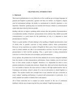
Topology
Objective
•
Observe what happens when the default spanning tree behavior is modified.
Background
Four switches have just been installed. The distribution layer switches are Catalyst 3560s, and the access
layer switches are Catalyst 2960s. There are redundant uplinks between the access layer and distribution
layer. Because of the possibility of bridging loops, spanning tree logically removes any redundant links. In this
lab, you will see what happens when the default spanning tree behavior is modified.
Note: This lab uses Cisco WS-C2960-24TT-L switches with the Cisco IOS image c2960-lanbasek9-mz.12246.SE.bin and Catalyst 3560-24PS switches with the Cisco IOS image c3560-advipservicesk9-mz.12246.SE.bin. Other switches (such as a 2950 or 3550) and Cisco IOS Software versions can be used if they
have comparable capabilities and features. Depending on the switch model and Cisco IOS Software version,
the commands available and output produced might vary from what is shown in this lab.
Required Resources
•
2 switches (Cisco 2960 with the Cisco IOS Release 12.2(46)SE C2960-LANBASEK9-M image or
comparable)
•
2 switches (Cisco 3560 with the Cisco IOS Release 12.2(46)SE C3560-ADVIPSERVICESK9-M
image or comparable)
•
1 PC (optional) attached to switch ALS1.
•
Ethernet and console cables
All contents are Copyright © 1992–2010 Cisco Systems, Inc. All rights reserved. This document is Cisco Public Information.
Page 1 of 12
CCNPv6 SWITCH
Note: Configuring PortFast in Step 5 requires a PC attached to one of the access switches.
Step 1: Prepare the switches for the lab.
a. Delete vlan.dat, erase the startup configuration, and reload all switches. You can find detailed instructions
in Lab 1-1 or 1-2.
b. Give each switch a hostname according to the topology diagram.
c.
Configure ports Fa0/7 through Fa0/12 on all switches to be trunks. On the 3560s, first set the trunk
encapsulation to dot1q. On the 2960s, only dot1q is supported, therefore the switchport trunk
encapsulation command is unavailable, but the mode still needs to be changed to trunk. If you do not set
the mode of the ports to trunk, they will negotiate the operational mode according to their default DTP
settings.
Note: The default mode on a 3560 or 2960 is dynamic auto; the default mode on a 3550 or 2950 is dynamic
desirable.
DLS1 example:
DLS1(config)# interface range fastEthernet 0/7 - 12
DLS1(config-if-range)# switchport trunk encapsulation dot1q
DLS1(config-if-range)# switchport mode trunk
Step 2: Display default spanning tree information for all switches.
a. Use the show spanning-tree command to check how the non-configured switches created a spanning
tree. Verify which switch became the root bridge. In the topology used in this lab, DLS2 is the root bridge.
DLS1# show spanning-tree
VLAN0001
Spanning tree enabled protocol ieee
Root ID
Priority
32769
Address
000a.b8a9.d680
Cost
19
Port
13 (FastEthernet0/11)
Hello Time
2 sec Max Age 20 sec
Bridge ID
Forward Delay 15 sec
Priority
32769 (priority 32768 sys-id-ext 1)
Address
000a.b8a9.d780
Hello Time
2 sec Max Age 20 sec Forward Delay 15 sec
Aging Time 300
Interface
---------------Fa0/7
Fa0/8
Fa0/9
Fa0/10
Fa0/11
Fa0/12
Role
---Desg
Desg
Desg
Desg
Root
Altn
Sts
--FWD
FWD
FWD
FWD
FWD
BLK
Cost
--------19
19
19
19
19
19
Prio.Nbr
-------128.9
128.10
128.11
128.12
128.13
128.14
Type
---------------------------P2p
P2p
P2p
P2p
P2p
P2p
DLS2# show spanning-tree
All contents are Copyright © 1992–2010 Cisco Systems, Inc. All rights reserved. This document is Cisco Public Information.
Page 2 of 12
CCNPv6 SWITCH
VLAN0001
Spanning tree enabled protocol ieee
Root ID
Priority
32769
Address
000a.b8a9.d680
This bridge is the root
Hello Time
2 sec Max Age 20 sec
Bridge ID
Forward Delay 15 sec
Priority
32769 (priority 32768 sys-id-ext 1)
Address
000a.b8a9.d680
Hello Time
2 sec Max Age 20 sec Forward Delay 15 sec
Aging Time 300
Interface
---------------Fa0/7
Fa0/8
Fa0/9
Fa0/10
Fa0/11
Fa0/12
Role
---Desg
Desg
Desg
Desg
Desg
Desg
Sts
--FWD
FWD
FWD
FWD
FWD
FWD
Cost
--------19
19
19
19
19
19
Prio.Nbr
-------128.9
128.10
128.11
128.12
128.13
128.14
Type
---------------------------P2p
P2p
P2p
P2p
P2p
P2p
ALS1# show spanning-tree
VLAN0001
Spanning tree enabled protocol ieee
Root ID
Priority
32769
Address
000a.b8a9.d680
Cost
19
Port
11 (FastEthernet0/9)
Hello Time
2 sec Max Age 20 sec
Bridge ID
Forward Delay 15 sec
Priority
32769 (priority 32768 sys-id-ext 1)
Address
0019.0635.5780
Hello Time
2 sec Max Age 20 sec Forward Delay 15 sec
Aging Time 300
Interface
---------------Fa0/7
Fa0/8
Fa0/9
Fa0/10
Fa0/11
Fa0/12
Role
---Altn
Altn
Root
Altn
Desg
Desg
Sts
--BLK
BLK
FWD
BLK
FWD
FWD
Cost
--------19
19
19
19
19
19
Prio.Nbr
-------128.9
128.10
128.11
128.12
128.13
128.14
Type
---------------------------P2p
P2p
P2p
P2p
P2p
P2p
ALS2# show spanning-tree
VLAN0001
Spanning tree enabled protocol ieee
Root ID
Priority
32769
Address
000a.b8a9.d680
Cost
19
Port
9 (FastEthernet0/7)
Hello Time
2 sec Max Age 20 sec
Bridge ID
Priority
32769
Forward Delay 15 sec
(priority 32768 sys-id-ext 1)
All contents are Copyright © 1992–2010 Cisco Systems, Inc. All rights reserved. This document is Cisco Public Information.
Page 3 of 12
CCNPv6 SWITCH
Address
0019.068d.6980
Hello Time
2 sec Max Age 20 sec
Aging Time 300
Interface
---------------Fa0/7
Fa0/8
Fa0/9
Fa0/10
Fa0/11
Fa0/12
Role
---Root
Altn
Altn
Altn
Altn
Altn
Sts
--FWD
BLK
BLK
BLK
BLK
BLK
Cost
--------19
19
19
19
19
19
Prio.Nbr
-------128.9
128.10
128.11
128.12
128.13
128.14
Forward Delay 15 sec
Type
---------------------------P2p
P2p
P2p
P2p
P2p
P2p
b. If you receive the following message “No spanning tree instance exists”, issue the no shutdown
command on all interfaces.
Switch# show spanning-tree
No spanning tree instance exists.
Switch# conf t
Switch(config)# interface range fastEthernet 0/1-24
Switch(config-if-range)# no shutdown
Switch(config-if-range)# end
Switch# show spanning-tree
Now that the switch is communicating with the other switches in the topology, you should receive spanning
tree output.
c.
Issue the show interfaces trunk command on DLS1 to verify the trunking mode, encapsulation and
status for the trunk links.
DSL1# show interfaces trunk
Port
Fa0/7
Fa0/8
Fa0/9
Fa0/10
Fa0/11
Fa0/12
Mode
on
on
on
on
on
on
Encapsulation
802.1q
802.1q
802.1q
802.1q
802.1q
802.1q
Port
Fa0/7
Fa0/8
Fa0/9
Fa0/10
Fa0/11
Fa0/12
Vlans allowed on trunk
1-4094
1-4094
1-4094
1-4094
1-4094
1-4094
Status
trunking
trunking
trunking
trunking
trunking
trunking
Native vlan
1
1
1
1
1
1
<output omitted>
Are BPDUs propagated without trunk links?
__________________________________________________________________________________
__________________________________________________________________________________
All contents are Copyright © 1992–2010 Cisco Systems, Inc. All rights reserved. This document is Cisco Public Information.
Page 4 of 12
CCNPv6 SWITCH
Step 3: Configure specific switches to be primary and secondary root.
In this step you configure other switches to be the primary root and secondary root. Because DLS2 is the root
switch in this topology, this lab changes DLS1 to be the primary root and ALS1 to be the secondary. Do the
same in your topology, regardless of which switch is the initial root. On one of the switches that you are not
changing, you can use the debug spanning-tree events command to monitor topology changes. To change
the spanning tree root status, use the global configuration commands spanning-tree vlan vlan_number root
primary and spanning-tree vlan vlan_number root secondary. On a switch that you are not going to be
modifying, issue the debug command and then watch the output.
a. Issue the debug command on DLS2.
DLS2# debug spanning-tree events
Spanning Tree event debugging is on
b. Change DLS1 to be the primary root switch.
DLS1(config)# spanning-tree vlan 1 root primary
c.
Change ALS1 to the secondary root.
ALS1(config)# spanning-tree vlan 1 root secondary
You can see the topology changes on the switch that you enabled debugging on (your output may vary
depending on your initial topology):
DLS2#
00:10:43:
00:10:43:
00:10:43:
19
00:10:43:
00:10:43:
00:10:53:
00:10:53:
00:10:53:
STP: VLAN0001 heard root 24577-000a.b8a9.d780 on Fa0/11
supersedes 32769-000a.b8a9.d680
STP: VLAN0001 new root is 24577, 000a.b8a9.d780 on port Fa0/11, cost
STP:
STP:
STP:
STP:
STP:
VLAN0001
VLAN0001
VLAN0001
VLAN0001
VLAN0001
sent Topology Change Notice on Fa0/11
Fa0/12 -> blocking
sent Topology Change Notice on Fa0/11
Fa0/9 -> blocking
Fa0/10 -> blocking
Notice the timestamps on the debugs to see the difference between changes caused by the commands done
in both steps.
d. Display the running config on the new root switches, DLS1 and ALS1.
DLS1# show run | include span
spanning-tree mode pvst
spanning-tree extend system-id
spanning-tree vlan 1 priority 24576
ALS1# show run | include span
spanning-tree mode pvst
spanning-tree extend system-id
spanning-tree vlan 1 priority 28672
Notice the spanning tree commands in the running configuration. You see a different command than the one
you entered. This is because spanning-tree vlan vlan_number root is a command that sets the priority
All contents are Copyright © 1992–2010 Cisco Systems, Inc. All rights reserved. This document is Cisco Public Information.
Page 5 of 12
CCNPv6 SWITCH
number on that VLAN automatically rather than typing in a specific priority number. The priority number of a
VLAN can be between 0 and 61440 in increments of 4096. To manually set the specific priority number, use
the spanning-tree vlan vlan_number priority priority_number command.
The command spanning-tree vlan vlan_number root primary sets the priority to 24576 instead of the default
(32768). The command spanning-tree vlan vlan_number root secondary sets the priority to 28672. Given
this information, would a lower or higher priority number result in a switch becoming the root bridge?
__________________________________________________________________________________
__________________________________________________________________________________
e. You can also view the priority modification with the show spanning-tree command:
DLS1# show spanning-tree
VLAN0001
Spanning tree enabled protocol ieee
Root ID
Priority
24577
Address
000a.b8a9.d780
This bridge is the root
Hello Time
2 sec Max Age 20 sec
Bridge ID
Forward Delay 15 sec
Priority
24577 (priority 24576 sys-id-ext 1)
Address
000a.b8a9.d780
Hello Time
2 sec Max Age 20 sec Forward Delay 15 sec
Aging Time 15
Interface
---------------Fa0/7
Fa0/8
Fa0/9
Fa0/10
Fa0/11
Fa0/12
Role
---Desg
Desg
Desg
Desg
Desg
Desg
Sts
--FWD
FWD
FWD
FWD
FWD
FWD
Cost
--------19
19
19
19
19
19
Prio.Nbr
-------128.9
128.10
128.11
128.12
128.13
128.14
Type
---------------------------P2p
P2p
P2p
P2p
P2p
P2p
Step 4: Change the root port using the spanning-tree port-priority command.
With spanning tree, you can also modify port priorities to determine which ports are forwarding and which are
blocking. To choose which port becomes the root on a non-root switch when faced with equal-cost redundant
root paths via the same neighbor, the switch looks at the port priorities first. If the sender port priorities are the
same, the switch picks the port that receives BPDUs with the lowest sender port number. On the link between
DLS1 and DLS2, the default forwarding port is Fa0/11 because it is lower, and the default blocking port is
Fa0/12 because it is higher. The two ports have equal costs because they have the same speed.
a. You can verify this using the show spanning-tree command on the non-root switch, which is DLS2.
DLS2# show spanning-tree
VLAN0001
Spanning tree enabled protocol ieee
Root ID
Priority
24577
Address
000a.b8a9.d780
Cost
19
Port
13 (FastEthernet0/11)
Hello Time
2 sec Max Age 20 sec
Forward Delay 15 sec
All contents are Copyright © 1992–2010 Cisco Systems, Inc. All rights reserved. This document is Cisco Public Information.
Page 6 of 12
CCNPv6 SWITCH
Bridge ID
Priority
32769 (priority 32768 sys-id-ext 1)
Address
000a.b8a9.d680
Hello Time
2 sec Max Age 20 sec Forward Delay 15 sec
Aging Time 300
Interface
---------------Fa0/7
Fa0/8
Fa0/9
Fa0/10
Fa0/11
Fa0/12
Role
---Desg
Desg
Altn
Altn
Root
Altn
Sts
--FWD
FWD
BLK
BLK
FWD
BLK
Cost
--------19
19
19
19
19
19
Prio.Nbr
-------128.9
128.10
128.11
128.12
128.13
128.14
Type
---------------------------P2p
P2p
P2p
P2p
P2p
P2p
b. For comparison, issue the show spanning-tree command on DLS1. Notice that all ports are forwarding
because it is the root switch.
DLS1# show spanning-tree
VLAN0001
Spanning tree enabled protocol ieee
Root ID
Priority
24577
Address
000a.b8a9.d780
This bridge is the root
Hello Time
2 sec Max Age 20 sec
Bridge ID
Forward Delay 15 sec
Priority
24577 (priority 24576 sys-id-ext 1)
Address
000a.b8a9.d780
Hello Time
2 sec Max Age 20 sec Forward Delay 15 sec
Aging Time 15
Interface
---------------Fa0/7
Fa0/8
Fa0/9
Fa0/10
Fa0/11
Fa0/12
Role
---Desg
Desg
Desg
Desg
Desg
Desg
Sts
--FWD
FWD
FWD
FWD
FWD
FWD
Cost
--------19
19
19
19
19
19
Prio.Nbr
-------128.9
128.10
128.11
128.12
128.13
128.14
Type
---------------------------P2p
P2p
P2p
P2p
P2p
P2p
Port priorities range from 0 to 240, in increments of 16. The default priority is 128, and a lower priority is
preferred. To change port priorities, change them on the switch closer to the root.
c.
To make DLS2 Fa0/12 the root port, and Fa0/11 block, change the port priority on DLS1 with the
interface-level command spanning-tree port-priority priority.
DLS1(config)# int fastEthernet 0/12
DLS1(config-if)# spanning-tree port-priority 112
d. Issue the show spanning-tree command to verify which port is blocking on DLS2.
DLS2# show spanning-tree
VLAN0001
Spanning tree enabled protocol ieee
All contents are Copyright © 1992–2010 Cisco Systems, Inc. All rights reserved. This document is Cisco Public Information.
Page 7 of 12
CCNPv6 SWITCH
Root ID
Bridge ID
Priority
Address
Cost
Port
Hello Time
24577
000a.b8a9.d780
19
14 (FastEthernet0/12)
2 sec Max Age 20 sec
Forward Delay 15 sec
Priority
32769 (priority 32768 sys-id-ext 1)
Address
000a.b8a9.d680
Hello Time
2 sec Max Age 20 sec Forward Delay 15 sec
Aging Time 15
Interface
---------------Fa0/7
Fa0/8
Fa0/9
Fa0/10
Fa0/11
Fa0/12
Role
---Desg
Desg
Altn
Altn
Altn
Root
Sts
--FWD
FWD
BLK
BLK
BLK
FWD
Cost
--------19
19
19
19
19
19
Prio.Nbr
-------128.9
128.10
128.11
128.12
128.13
128.14
Type
---------------------------P2p
P2p
P2p
P2p
P2p
P2p
On DLS2, although the root port has changed, the port priorities have not. On DLS1, you can see the port
priorities have changed, although all ports are still forwarding (because it is the root switch).
DLS1# show spanning-tree
VLAN0001
Spanning tree enabled protocol ieee
Root ID
Priority
24577
Address
000a.b8a9.d780
This bridge is the root
Hello Time
2 sec Max Age 20 sec
Bridge ID
Forward Delay 15 sec
Priority
24577 (priority 24576 sys-id-ext 1)
Address
000a.b8a9.d780
Hello Time
2 sec Max Age 20 sec Forward Delay 15 sec
Aging Time 15
Interface
---------------Fa0/7
Fa0/8
Fa0/9
Fa0/10
Fa0/11
Fa0/12
Role
---Desg
Desg
Desg
Desg
Desg
Desg
Sts
--FWD
FWD
FWD
FWD
FWD
FWD
Cost
--------19
19
19
19
19
19
Prio.Nbr
-------128.9
128.10
128.11
128.12
128.13
112.14
Type
---------------------------P2p
P2p
P2p
P2p
P2p
P2p
Using the above output, how does DLS2 know which port to change to the root port, without changing the port
priorities on DLS2?
__________________________________________________________________________________
__________________________________________________________________________________
All contents are Copyright © 1992–2010 Cisco Systems, Inc. All rights reserved. This document is Cisco Public Information.
Page 8 of 12
CCNPv6 SWITCH
Step 5: Configure PortFast on an access port.
a. (Optional) If you have a host attached to ASL1 Fa0/6 you can perform this step. If not, read through the
following information to see how a port goes through the spanning tree states with and without PortFast
enabled.
Another feature of spanning tree is PortFast. PortFast allows you to bypass the normal states of IEEE 802.1D
spanning tree and move a port to the forwarding state as soon as it is turned on. This is useful when
connecting hosts to a switch, because they can start communicating on the VLAN instantly rather than waiting
for spanning tree. There is no danger of creating a spanning tree loop because you are not connecting
another switch. A client that runs DHCP as soon as it starts up benefits, because the DHCP requests could
be ignored if the port was not in the spanning tree forwarding state. PortFast must be used carefully to avoid
inadvertently creating spanning tree loops.
b. Ensure that the port to which the host is attached (Fa0/6) on ALS1 is shut down initially.
ALS1(config)# interface fastEthernet 0/6
ALS1(config-if)# shutdown
c.
Enable spanning tree debugging on ALS1.
ALS1# debug spanning-tree events
Spanning Tree event debugging is on
d. Set port Fa0/6 switchport mode to access, enable the port and observe the debug output. Notice what
happens when the port is brought up. Your output may vary.
ALS1(config)# interface fastEthernet 0/6
ALS1(config-if)# switchport mode access
ALS1(config-if)# no shut
ALS1(config-if)# end
ALS1#
22:32:23: set portid: VLAN0001 Fa0/6: new port id 800D
22:32:23: STP: VLAN0001 Fa0/6 -> listening
22:32:25: %LINK-3-UPDOWN: Interface FastEthernet0/6, changed state to up
22:32:26: %LINEPROTO-5-UPDOWN: Line protocol on Interface FastEthernet0/6,
changed state to up
22:32:38: STP: VLAN0001 Fa0/6 -> learning
22:32:53: STP: VLAN0001 Fa0/6 -> forwarding
22:32:53: STP: VLAN0001 sent Topology Change Notice on Fa0/7
e. Shut down the port for the next part.
ALS1(config)# interface fastEthernet 0/6
ALS1(config-if)# shutdown
f.
Activate PortFast on the port with the interface-level command spanning-tree portfast. The switch warns
you about the possibility of creating switching loops.
ALS1(config)# interface fastEthernet 0/6
ALS1(config-if)# spanning-tree portfast
%Warning: portfast should only be enabled on ports connected to a single
host. Connecting hubs, concentrators, switches, bridges, etc... to this
All contents are Copyright © 1992–2010 Cisco Systems, Inc. All rights reserved. This document is Cisco Public Information.
Page 9 of 12
CCNPv6 SWITCH
interface when portfast is enabled, can cause temporary bridging loops.
Use with CAUTION
%Portfast has been configured on FastEthernet0/6 but will only
have effect when the interface is in a non-trunking mode.
g. Now, bring up the port by issuing the no shutdown command on the interface.
ALS1(config-if)# no shutdown
22:43:23: set portid: VLAN0001 Fa0/6: new port id 800D
22:43:23: STP: VLAN0001 Fa0/6 ->jump to forwarding from blocking
22:43:25: %LINK-3-UPDOWN: Interface FastEthernet0/6, changed state to up
22:43:26: %LINEPROTO-5-UPDOWN: Line protocol on Interface FastEthernet0/6,
changed state to up
h. Be sure to turn off debugging before continuing:
ALS1(config-if)# end
ALS1#
22:55:23: %SYS-5-CONFIG_I: Configured from console by console
ALS1# undebug all
All possible debugging has been turned off
Why could enabling portfast on redundant switch access links be a bad idea?
__________________________________________________________________________________
__________________________________________________________________________________
Note: The spanning-tree portfast trunk interface-level command can be useful if a trunk is being connected
to a router or a server. If RSTP is used, both trunk and access links can be moved to a forwarding state
rapidly. The spanning-tree portfast trunk command is to be used only on trunks connected to non-switching
devices.
Step 6: Change root port using the spanning-tree cost command.
Another way of changing which port becomes the root is to modify the port costs using the interface command
spanning-tree cost cost. The default cost is 4 for a gigabit Ethernet port, 19 for a Fast Ethernet port, and 100
for a 10baseT Ethernet port. Lower cost is preferred.
Note: Each port has a default cost value based on a guideline established as part of IEEE 802.1d. In the
original specification, the cost of a port cost is calculated as 1,000 Mbps (1 gigabit per second) divided by the
bandwidth at which the port is functioning. A 10 Mbps connection have a cost of (1,000/10) or 100. As the
speed of networks has increased beyond gigabit, the standard cost has been modified somewhat. The new
cost values are:
Bandwidth
STP Cost
4 Mbps
250
10 Mbps
100
16 Mbps
62
45 Mbps
39
100 Mbps
19
All contents are Copyright © 1992–2010 Cisco Systems, Inc. All rights reserved. This document is Cisco Public Information.
Page 10 of 12
CCNPv6 SWITCH
155 Mbps
14
622 Mbps
6
1 Gbps
4
10 Gbps
2
a. For this scenario, change the cost of port Fa0/10 on ALS2. First, look at the current port costs using the
show spanning-tree command.
Note: The cost shown here is for the port. The root bridge path cost is the sum of link port costs between a
switch and the root bridge. The cost of traversing this path is the sum of the costs of the segments on the
path. This determines how far away the root bridge is.
ALS2# show spanning-tree
VLAN0001
Spanning tree enabled protocol ieee
Root ID
Priority
24577
Address
000a.b8a9.d780
Cost
19
Port
11 (FastEthernet0/9)
Hello Time
2 sec Max Age 20 sec
Bridge ID
Forward Delay 15 sec
Priority
32769 (priority 32768 sys-id-ext 1)
Address
0019.068d.6980
Hello Time
2 sec Max Age 20 sec Forward Delay 15 sec
Aging Time 300
Interface
---------------Fa0/7
Fa0/8
Fa0/9
Fa0/10
Fa0/11
Fa0/12
Role
---Altn
Altn
Root
Altn
Altn
Altn
Sts
--BLK
BLK
FWD
BLK
BLK
BLK
Cost
--------19
19
19
19
19
19
Prio.Nbr
-------128.9
128.10
128.11
128.12
128.13
128.14
Type
---------------------------P2p
P2p
P2p
P2p
P2p
P2p
Note that Fa0/9 is currently the root port.
b. Change the port cost for Fa0/10 on ALS2 to 10 and then issue the show spanning-tree command.
ALS2(config)# interface fastEthernet 0/10
ALS2(config-if-range)# spanning-tree cost 10
ALS2# show spanning-tree
VLAN0001
Spanning tree enabled protocol ieee
Root ID
Priority
24577
Address
000a.b8a9.d780
Cost
10
All contents are Copyright © 1992–2010 Cisco Systems, Inc. All rights reserved. This document is Cisco Public Information.
Page 11 of 12
CCNPv6 SWITCH
Port
Hello Time
Bridge ID
12 (FastEthernet0/10)
2 sec Max Age 20 sec
Forward Delay 15 sec
Priority
32769 (priority 32768 sys-id-ext 1)
Address
0019.068d.6980
Hello Time
2 sec Max Age 20 sec Forward Delay 15 sec
Aging Time 300
Interface
---------------Fa0/7
Fa0/8
Fa0/9
Fa0/10
Fa0/11
Fa0/12
Role
---Altn
Altn
Altn
Root
Altn
Altn
Sts
--BLK
BLK
FWD
FWD
BLK
BLK
Cost
--------19
19
19
10
19
19
Prio.Nbr
-------128.9
128.10
128.11
128.12
128.13
128.14
Type
---------------------------P2p
P2p
P2p
P2p
P2p
P2p
All contents are Copyright © 1992–2010 Cisco Systems, Inc. All rights reserved. This document is Cisco Public Information.
Page 12 of 12